Vendors Exchange CURVE AP 113 User manual

INSTALLATION GUIDE
CURVE™ Door
AP 113, AP 123, AP 7000
R
www.veii.com
1.800.321.2311
8700 BROOKPARK ROAD
CLEVELAND, OHIO 44129
VE1015205, REV B. ©2021, VENDORS EXCHANGE® INTERNATIONAL, USA
AP 113, AP 123, AP 7000 - PLATINUM AP 113, AP 123, AP 7000 - BLACK
R

2 CURVE™ Door AP 113, AP 123, AP 7000
TABLE OF CONTENTS
INSTALLATION GUIDE
What’s on These Pages
PRECAUTIONARY SYMBOLS ........................................................................................................ 3
TOOLS NEEDED ............................................................................................................................ 4
SERVICE KITS − CURVE DOOR...................................................................................................... 5
SERVICE PARTS − DROP SENSOR ................................................................................................ 6
SERVICE PARTS − LABELS............................................................................................................ 6
SERVICE PARTS − LED.................................................................................................................. 6
SERVICE PARTS − TRIM AND TRIM LIGHTING .............................................................................. 6
SERVICE PARTS − UCB™ .............................................................................................................. 7
SERVICE PARTS − DOOR............................................................................................................... 7
SERVICE PARTS − SPIRALS .......................................................................................................... 7
SERVICE PARTS − MOTORS .......................................................................................................... 8
SERVICE PARTS − GLASS.............................................................................................................. 8
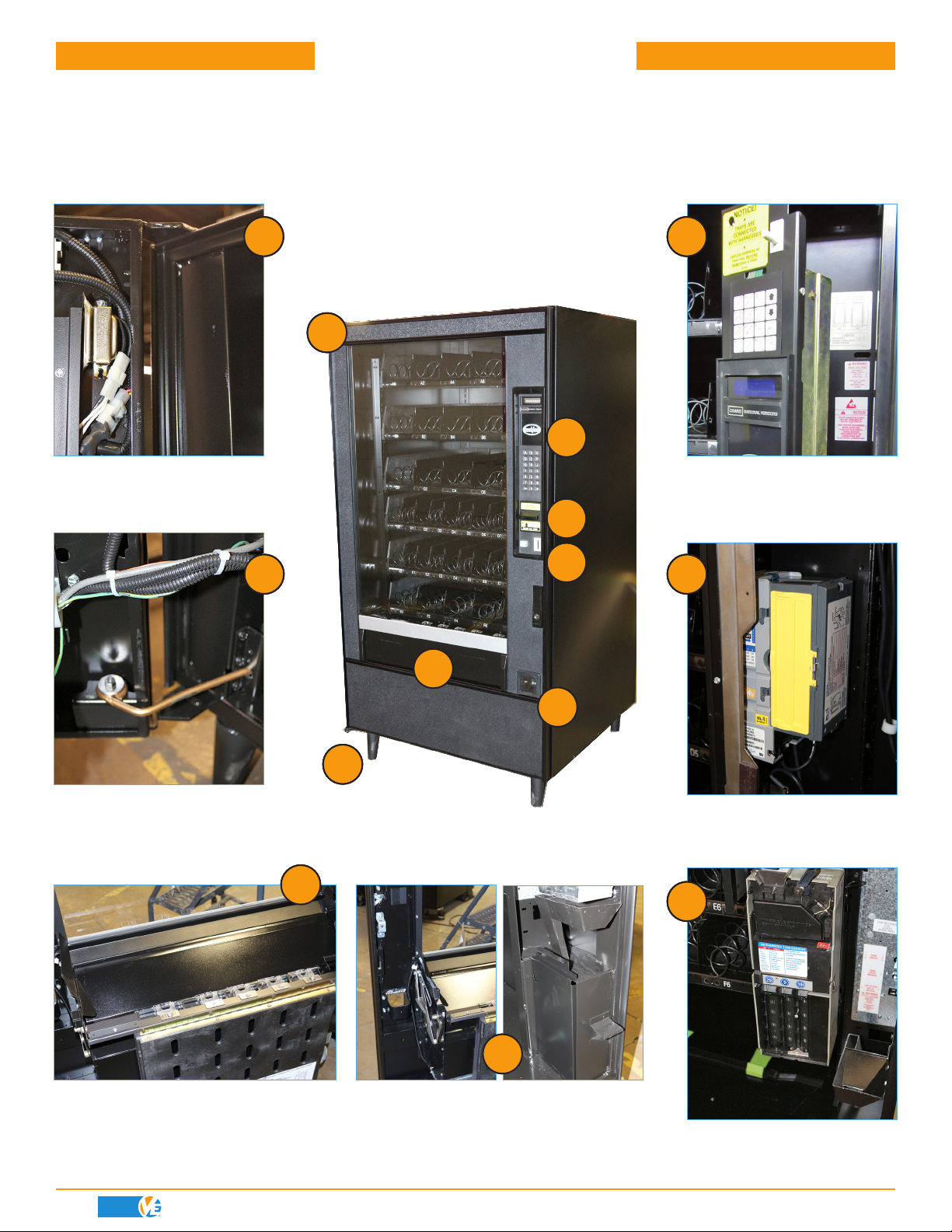
DOOR OVERVIEW − OEM DOOR .................................................................................................. 10
DOOR OVERVIEW − CURVE DOOR .............................................................................................. 11
REMOVE OEM DOOR, PREPARE FOR CURVE DOOR.................................................................... 12
INSTALL THE CURVE DOOR........................................................................................................ 18
ROUTE AND CONNECT HARNESSES .......................................................................................... 21
INSTALL THE VEND BUCKET ...................................................................................................... 24
COMPLETE INSTALLATION ......................................................................................................... 28
ADJUST THE DOOR .................................................................................................................... 32
UCB™ CONNECTIONS FOR CURVE™ DOOR................................................................................ 33
PRODUCT WARRANTY ............................................................................................................... 36
To navigate this installation guide:
Click or touch each chapter title above to go directly to that section or pages and it will take you immediately to
that page via a hyperlink. Any pages with italicized words are links to other sections and pages and by clicking
or touching those links will also take you back and forth within this installation guide. The VE logo in the lower
corner of each page links back to the Table of Contents

3CURVE™ Door AP 113, AP 123, AP 7000
PRECAUTIONARY SYMBOLS
INSTALLATION GUIDE
WHAT THE SYMBOLS MEAN
WARNING, CAUTION, and NOTICE statements are used in this installation manual to stress important
and critical information to safely service this door. These statements, according to the American National
Standards (ANSI), are described below.
WARNING
THIS SYMBOL INDICATES A HAZARDOUS SITUATION WHICH, IF NOT AVOIDED, COULD
RESULT IN DEATH OR SERIOUS INJURY.
NOTICE
THIS STATEMENT IS USED TO ADDRESS PRACTICES NOT RELATED TO PHYSICAL INJURIES
OR SITUATIONS THAT WILL NOT CAUSE HARM.
THIS SYMBOL INDICATES A HAZARDOUS SITUATION WHICH, IF NOT AVOIDED, COULD
RESULT IN MINOR OR MODERATE INJURY.
CAUTION
PLEASE READ THESE INSTRUCTIONS THOROUGHLY BEFORE INSTALLING
THE CURVE DOOR. IF YOU NEED ANY ASSISTANCE, CALL 1-800-321-2311
R
To TOC

INSTALLATION GUIDE
4
TOOLS NEEDED
TOOLS TO USE FOR PROCEDURES IN THIS MANUAL
CURVE™ Door AP 113, AP 123, AP 7000
5/32” HEX KEY
(ALLEN
WRENCH)
7/16” BOX
WRENCH
PHILLIPS
SCREW-
DRIVER
FLAT HEAD
SCREW-
DRIVER
11/32” NUT
DRIVER
5/16” NUT
DRIVER
STANDARD
SOCKET SET
SIDE/WIRE
CUTTERS
CORDLESS DRILL WITH 1/4” SOCKETFLASHLIGHT CRESCENT
WRENCH
SOME IMAGES USED IN THIS MANUAL ARE FOR ILLUSTRATIVE PURPOSES
ONLY AND MAY NOT BE SPECIFIC TO THE CURVE DOOR FOR
AP 113, AP 123, AND AP 7000.
ANY FURTHER QUESTIONS CALL 800-321-2311
R
Overview
R
To TOC

INSTALLATION GUIDE
5
SERVICE KITS − CURVE DOOR
CURVE™ Door AP 113, AP 123, AP 7000
PART NUMBER DESCRIPTION QTY.
VE1581 ITEM TABS 1
VE4653K 1/2 IN. BLACK NYLON CABLE CLAMP 1
VE4650K 4 - WAY TIE MOUNT 10
VE4601K 6 IN. WHITE CABLE TIE 10
VE4849 ENERGY SAVING LED CLING - ON LABEL 1
VE5800 UCB PROGRAMMING INSTRUCTION GUIDE 1
VE5876 REFUND CLING - ON LABEL 1
VE6801R CASH BOX W/ INSTALLED WING HANDLE CAM LATCH (VE6831) 1
VE68010 HINGE SHIM PLATE 1
VE6801Q BOTTOM HINGE PLATE 1
VE8745 BOTTOM DOOR HINGE 1
VED3584 TOP HINGE PLATE 1
VED3583 UPPER HINGE 1
VE7358 1/4-20 KEPS NUT 1
VE6836 SCREW, FLAT HEAD SOCKET CAP, 1/4-20 X 7/8 IN. 2
VE7387 SCREW, SERRATED HEX FLANGE, 1/4-20 X 3/4 IN. 1
VE8714 SCREW, HEX HEAD CAP, 5/16-18 X 3/8 IN. 1
VE8714A WASHER, EXTERNAL TOOTH, 5/16 IN. 1
VE8718A WASHER, BRASS, 1/2 IN. 3
VED3596 BLOCK OUT PLATE (IF NO 7TH TRAY INSTALLED) 1
VE8716 CABINET SUPPORT BRACKET (AP 7000 ONLY) 1
VED3597 INNER PANEL (INNER FILLER BAR - AP 113 AND AP 123 ONLY) 1
VE7373K SCREW, SELF-TAPPING, #8-18 X 1/2 IN. 4
VE1015205 INSTALLATION MANUAL 1
R
Overview
R
To TOC

INSTALLATION GUIDE
6
SERVICE PARTS − DROP SENSOR
SERVICE PARTS − LABELS
CURVE™ Door AP 113, AP 123, AP 7000
PART NUMBER DESCRIPTION
VE6886 ADA DROP SENSOR TRANSMITTER (BUCKET LINKAGE SIDE)
VE6887 ADA DROP SENSOR RECEIVER (HINGE SIDE)
PART NUMBER DESCRIPTION
VE1581 ITEM TABS − NUMBERS 110 − 189
VE673 (SERIES) PRICE LABELS (SPECIFY PRICES)
VE5876 REFUND LABEL (DROP SENSOR LABEL)
SERVICE PARTS − LED
PART NUMBER DESCRIPTION
VEL1410RD LED LIGHT BAR KIT (3 LED LIGHTS)
VEL1410 LED LIGHT BAR (1 LED LIGHT)
VE5829C LED MOTION SENSOR
SERVICE PARTS − TRIM AND TRIM LIGHTING
PART NUMBER DESCRIPTION
VE1015177 LENS
VE1016283 SIDE TRIM, PAINTED
VE1015179 BOTTOM TRIM, PAINTED
VE1016553 CORNER, CURVE DOOR PAINTED
VE1016549 HEADER, RIGHT SIDE PAINTED
VE1016551 HEADER, LEFT SIDE PAINTED
VE1016117 LED LIGHT STRIP, SIDE
R
Overview
R
To TOC

INSTALLATION GUIDE
7
SERVICE PARTS − UCB™
SERVICE PARTS − DOOR
SERVICE PARTS − SPIRALS
CURVE™ Door AP 113, AP 123, AP 7000
PART NUMBER DESCRIPTION
VE5801 UNIVERSAL CONTROL BOARD
VE5816 MDB HARNESS
VE5853D DISPLAY HARNESS
VE5861DF HARNESS BOARD FORCED
VE5862 DISPLAY BOARD
VE6820 DEX HARNESS
PART NUMBER DESCRIPTION
VE1529 DOOR SWITCH
VED3567 LOCK BAR
VED3562 KEY PAD
VE8712 COIN CHUTE
VED6341PB COIN RETURN BUTTON ASSEMBLY
PART NUMBER DESCRIPTION
VE713 SNACK, 6 COUNT − RIGHT HAND
VE710 SNACK, 10 COUNT − RIGHT HAND
VE715 SNACK, 12 COUNT − RIGHT HAND
VE715A CANDY, 12 COUNT − LEFT HAND
VE1508 CANDY, 12 COUNT − RIGHT HAND
VE716 CANDY, 15 COUNT − RIGHT HAND
VE716A CANDY, 15 COUNT − LEFT HAND
VE711 CANDY, 18 COUNT − RIGHT HAND
VE715A/VE1508 SNACK, 12 COUNT − DUAL
VE716/VE716A SNACK, 15 COUNT − DUAL
R
Overview
R
To TOC

INSTALLATION GUIDE
8
SERVICE PARTS − MOTORS
SERVICE PARTS − GLASS
CURVE™ Door AP 113, AP 123, AP 7000
PART NUMBER DESCRIPTION
VE2995 SINGLE SPIRAL VEND MOTOR (AP 113, AP 7000)
VE8317 DUAL SPIRAL VEND MOTOR (AP 113, AP 7000)
VE8322 SINGLE SPIRAL VEND MOTOR (AP 123)
VE8320 DUAL SPIRAL VEND MOTOR (AP 123)
PART NUMBER DESCRIPTION
VED3542 42.36 X 24.63 (TEMPERED)
R
Overview
R
To TOC

INSTALLATION GUIDE
10
DOOR OVERVIEW − OEM DOOR
CURVE™ Door AP 113, AP 123, AP 7000
Inside Location of Top Hinge
and Mounting Plate
Inside Location of Vend Bucket and
Harnesses
Inside Location of Bottom
Door Hinge and Door Stop
Inside Locations of Coin Chute and Coin
Box
Inside Location of Coin
Mechanism
Inside Location of Card
Validator
Location of Touch Pad, Lens
Display and Display Board
and Machine Switch
7
7
5
5
4
4
3
32
2
1
1
6
6
7
7
5
5
4
4
3
32
2
1
1
6
6
All Descriptions Linked to Sections in this Manual
Highlight the Text, Then Click with Your Mouse or Finger
7
7
5
5
4
4
3
32
2
1
1
6
6
R
To TOC

INSTALLATION GUIDE
11
DOOR OVERVIEW − CURVE DOOR
CURVE™ Door AP 113, AP 123, AP 7000
Inside Location of UCB Board
Inside Location of Card Validator
and Door Switch.
Inside Location of Vend Bucket.
Inside Location of Cash Box
(Mounted inside Cabinet)
Inside Location of Bottom Door Hinge and
Door Stop
Inside Location of Top Hinge
and Mounting Plate
Inside Location of Delivery
Bucket and Harnesses
1
1
2
2
3
3
4
4
5
5
6
6
7
7
All Descriptions Linked to Sections in this Manual
Highlight the Text, Then Click with Your Mouse or Finger
R
To TOC

NOTE: This is a tight area of the machine,
use smaller screwdriver to remove.
TO AVOID POTENTIAL
INJURY, IT IS HIGHLY
RECOMMENDED
THAT THE CURVE
DOOR IS INSTALLED
BY TWO QUALIFIED
INSTALLERS
DO NOT REMOVE
THE TRAYS FROM
THE CABINET. THE
CABINET COULD
BECOME
UNSTEADY AND
RESULT IN DAMAGE
OR
PERSONAL INJURY
TO PREVENT
PERSONAL INJURY
AND EQUIPMENT
DAMAGE, TURN
MACHINE OFF
AND DISCONNECT
ELECTRICAL CORD
FROM THE WALL
OUTLET TO PREVENT
ELECTRICAL SHOCK
TEST THE MACHINE
THAT IT IS IN
WORKING ORDER
BEFORE REPLACING
THE DOOR.
SERVICE SHOULD
BE PERFORMED
BY QUALIFIED
PERSONNEL
NOTICE
WARNING WARNING CAUTION
12
REMOVE OEM DOOR, PREPARE FOR CURVE DOOR
CURVE™ Door AP 113, AP 123, AP 7000
REMOVE OEM DOORINSTALL DOORHARNESSESINSTALL BUCKETFINAL INSTALLADJUST DOOR
First, for AP 113 and AP 123, remove control board cover by loosening
Phillips Head Screw at top, right edge of the cover. Discard the cover.
Next, for AP 7000, slide selection panel
forward, then loosen (4) screws holding the
inner sliding panel.
Then, for the AP 7000, remove the control
board cover by loosening the Phillips Head
Screws holding the board to the inner side
panel, then discard cover.
INSTALLATION GUIDE
(Continued next page)
R
Overview
R
To TOC
3
AP 7000
AP 7000
2
AP 123AP 113
1
Loosen Screw
Control Board
Cover
Control Board
Cover
Selection Panel
Screws
Screws

REMOVE OEM DOORINSTALL DOOR
HARNESSES INSTALL BUCKET
FINAL INSTALLADJUST DOOR
13
REMOVE OEM DOOR, PREPARE FOR CURVE DOOR
CURVE™ Door AP 113, AP 123, AP 7000
REMOVE OEM DOOR INSTALL DOOR FINAL INSTALL ADJUST DOOR
Then, for AP 7000, AP 113, and AP
123, unplug all harnesses from existing
controller circuit board. The AP 113
(A) and AP 7000 (B) are shown here as
examples.
Next, if present, remove the validator
(A) and coin mech (B). If they are MDB,
set them aside for future
installation.
Then, for AP 113 and AP 123, loosen
Phillips screws to remove swing panel
from the cabinet wall.
Next, for the AP 113 and the AP 123, remove the cash box and
loosen the cash box mounting assembly from the lower right
side of the cabinet and discard. For the AP 7000, remove the
cash box and remove the cash box mounting assembly from
right side of the cabinet.
INSTALLATION GUIDE
6
(Continued next page)
Card Validator Coin Mech
R
Overview
R
To TOC
5
AP 113
4
AP 7000
AP 113, AP 123
A
A
B
B

14
REMOVE OEM DOOR, PREPARE FOR CURVE DOOR
CURVE™ Door AP 113, AP 123, AP 7000
Then, if a gum and mint tray are available, remove it from
the cabinet by sliding the plate forward and unfastening (4)
screws from under the tray.
Then, remove the screws on the side tray (filler) attached
to the left side of the cabinet.
First, using a Phillips screwdriver or the cordless drill
with a Phillips Head driver, remove the gum and mint
bracket from inside the cabinet.
INSTALLATION GUIDE
AP 7000 VARIATION
(Continued next page)
HARNESSESINSTALL BUCKET REMOVE OEM DOORINSTALL DOORFINAL INSTALLADJUST DOOR
R
Overview
R
To TOC
Screw
Side Tray
2
1
Gum and Mint Tray
Bracket
Screw
Gum and Mint Tray
Screw Locations
5

REMOVE OEM DOORINSTALL DOOR
HARNESSES INSTALL BUCKET
FINAL INSTALLADJUST DOOR
15
REMOVE OEM DOOR, PREPARE FOR CURVE DOOR
CURVE™ Door AP 113, AP 123, AP 7000
REMOVE OEM DOOR INSTALL DOOR FINAL INSTALL ADJUST DOOR
Next, loosen screw from gum and mint deflector plate
as shown.
Finally, loosen the screw from the left and right front
roller guide (detail). This image shows the left side
roller guide. Retain guides for further installation.
Then, loosen (2) screws on gum and mint tray slide
from both sides of the cabinet.
INSTALLATION GUIDE
AP 7000 VARIATION
(Continued next page)
R
Overview
R
To TOC
Right/Left Front of
Roller Guide
Loosen Screw
Gum and Mint
Deflector Plate
Gum and Mint
Tray Slide
Screws

NOTE: The AP 7000 does not have a ballast filler panel like
the AP 113 and AP 123.
16
REMOVE OEM DOOR, PREPARE FOR CURVE DOOR
CURVE™ Door AP 113, AP 123, AP 7000
Then, for AP 113 and AP 123, uninstall top bracket assem-
bly by removing the bolt from under ballast filler panel and
sliding bracket out of the housing. For AP 7000, remove the
bolt directly under hinge assembly on inside of the cabinet
Next, uninstall the door stop arm from inside the OEM door.
Leave the other end of door stop arm in the cabinet. Set fas-
teners aside to install new door.
Next, for the AP 7000, pull the main harness through the
opening and into the bottom of the cabinet.
Then, remove cabinet main harness from OEM door and if
present, disconnect the ground wire.
INSTALLATION GUIDE
(Continued next page)
HARNESSESINSTALL BUCKET REMOVE OEM DOOR
INSTALL DOOR
FINAL INSTALLADJUST DOOR
R
Overview
R
To TOC
Housing
Bolt
Ballast Filler Panel
Main Harness
Opening
Door Stop Arm

REMOVE OEM DOORINSTALL DOORHARNESSESINSTALL BUCKETFINAL INSTALLADJUST DOOR
17
REMOVE OEM DOOR, PREPARE FOR CURVE DOOR
CURVE™ Door AP 113, AP 123, AP 7000
REMOVE OEM DOOR INSTALL DOOR FINAL INSTALL ADJUST DOOR
For AP 113 and AP 123, loosen the top screw only of
the ballast filler panel on the inside of the machine to
access top bracket fastener.
Then, for the AP 113, and AP 123 from inside the machine
cabinet, loosen all the inner panel screws (see arrows) and
set aside for “Install Curve Door”, Step 7 on page 20. (2)
screws are shown in the image on the left, then remove pan-
el from the cabinet. No inner panel exists for the AP 7000.
Align Top Hinge Shim Plate (VED3584) as shown in
image (A). Insert upper hinge stud (circular impression on
hinge) in hole on door and align threaded hole with hole
on shim and door as shown in image (B).
INSTALLATION GUIDE
THIS SECTION IS COMPLETE,
MOVE ON TO NEXT SECTION
INSTALL BUCKET HARNESSES
R
Overview
R
To TOC
Threaded Hole
Hole in Door
Inner Panel
Ballast Filler Panel
AP 113, AP 123
AP 113, AP 123
Top Shim Plate
A
Upper Hinge Stud

18 CURVE™ Door AP 113, AP 123, AP 7000
INSTALL THE CURVE DOOR
INSTALLATION GUIDE
Then slide Top Hinge Plate (VE8718) into housing on top
of cabinet. For AP 113, and AP 123, install Bolt (VE7387)
on inside of ballast filler panel to secure the hinge.
For AP 7000, fasten (VE7387) directly under hinge assem-
bly on inside of the cabinet.
Next, position Bottom Hinge Plate (VE6801Q) in lower right
corner of the CURVE door as shown.
Then, hold bottom hinge plate and insert (2) Flat Head Screws
(VE6836) through the Bottom Hinge Plate from the bottom of
the door and the plate as shown.
First, remove the original bottom bracket and
install new Bottom Hinge Plate in the same location
as shown in image on (Step 1, Page 19, Image A).
INSTALLATION GUIDE
3
Bottom of Curve
Door
(Continued next page)
REMOVE OEM DOORINSTALL DOORHARNESSESINSTALL BUCKETFINAL INSTALLADJUST DOOR
R
Overview
R
To TOC
4
From Underneath Door and
Plate
2
Ensure Angle of Hinge Mount
Hold to 90O for Proper Open/
Close of Door
1
OEM Hinge
Plate
Top Of Cabinet
Hinge
Assembly
Align To Holes
Bolt
(2) Screws

NOTE: Support bottom of CURVE door so it stays aligned with the height of the bottom
hinge. Doing so makes sure the door will close properly when installation is completed.
Hold to 90O for Proper Open/
Close of Door
Ensure Angle of Hinge Mount
19CURVE™ Door AP 113, AP 123, AP 7000
INSTALL THE CURVE DOOR
REMOVE OEM DOOR INSTALL DOOR HARNESSES INSTALL BUCKET FINAL INSTALL ADJUST DOOR
First, align (3) 1/2” Brass Wash-
ers (VE8718A) over the hole in
the bottom bracket (A), then in-
sert the pin from the bottom hinge
plate attached to the underside
of the CURVE Door through the
brass washers into the hole in the
bottom bracket (B).
INSTALLATION GUIDE
Then, align and position Top Hinge Plate
(VE6801P) to holes from the CURVE door,
Top Hinge Shim Plate (VE6801O), and the
Top Hinge (Reference Step 11, Page 17) on
the as shown in the image.
Then, insert (2) 1/2-20 Flat Head Screws
(VE6836) through the Top Hinge, Top Hinge
Shim Plate, and the CURVE door, threading
them into the Top Hinge Plate as shown.
5
(Continued next page)
Bracket Hole
Align Washers
Bottom Hinge
Hinge Plate
R
Overview
R
To TOC
6
Flat Head
Screws
Top Hinge
Plate
Top Hinge
Plate
Top of the Cabinet
Top of the Cabinet
7
AB

NOTE: The inner panel (inner filler bar) is the long, slender bar
between the power supply and the trays (arrow shown). the
inner filler bar does not apply to the AP 7000
20 CURVE™ Door AP 113, AP 123, AP 7000
INSTALL THE CURVE DOOR
REMOVE OEM DOORINSTALL DOORHARNESSESINSTALL BUCKETFINAL INSTALLADJUST DOOR
Then, for AP 113, and AP 123, tighten top
screw of ballast filler panel (see arrow).
Next, attach the door stop arm to inside stud
closest to the inner door frame (see arrow) and
turn 1-1/2 turns from tight.
Next, for the AP 113, and AP 123, align Inner Panel
(VED3597) slotted key ways with existing holes. Then, reinstall
screws removed from “Removing OEM Door”, Step 10 on page
17, allowing ample space to hang inner panel on slotted key
ways.
After hanging the inner panel, insert Phillips screwdriver
through the inner panel holes as shown to tighten all
screws in each key way.
INSTALLATION GUIDE
10
11
Ballast Filler
Panel
Trays
THIS SECTION IS COMPLETE,
MOVE ON TO NEXT SECTION
R
Overview
R
To TOC
Power Supply
Cover
8
Closest Stud
Inner Door Frame
9
This manual suits for next models
2
Table of contents
Other Vendors Exchange Vending Machine manuals
Popular Vending Machine manuals by other brands

PharmaShop24
PharmaShop24 Extensive Instruction, use and maintenance manual

SCRUB TRAK
SCRUB TRAK VendNet 3599 Service manual

FAS International
FAS International FASTER TMT manual

Coinco
Coinco BillPro Operation and service manual

Intralot
Intralot OHIO MPNG manual

Westomatic
Westomatic SIGMA Operator's & installation manual