Verde VER-EVC-7 User manual

AC CHARGER USER MANUAL
VER-EVC-7

- 1 -
Contents
Safety Instruction ..........................................................................................................................................- 2 -
1 Product Overview.......................................................................................................................................- 3 -
1.1 Product Introduction.....................................................................................................................- 3 -
1.2 Schematic Diagram........................................................................................................................- 3 -
1.3 Specification Parameter ................................................................................................................- 3 -
1.4 Performance and Characteristics......................................................... Error! Bookmark not defined.
1.5 Working Environment ...................................................................................................................- 5 -
1.6 Product Naming ............................................................................................................................- 6 -
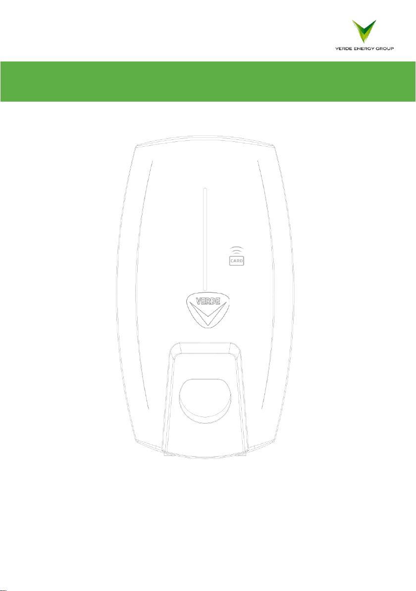
1.7 Product Structure..........................................................................................................................- 6 -
1.7.1 External Structure ............................................................................................................- 6 -
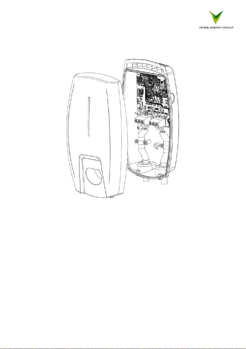
1.7.2 Internal Structure.............................................................................................................- 7 -
2 Operation Instruction .................................................................................................................................- 8 -
2.1 Product Installation.......................................................................................................................- 8 -
2.1.1 Package Verification.........................................................................................................- 8 -
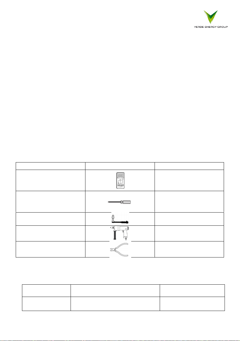
2.1.2 Installation Preparation....................................................................................................- 8 -
2.1.3 Installation Process ..........................................................................................................- 9 -
2.2 Power-on Checking......................................................................................................................- 10 -
2.3 Charging Operation .....................................................................................................................- 11 -
2.3.1 Connect Charger to EV...................................................................................................- 11 -
2.3.2 Start Charging & Stop Charging......................................................................................- 11 -
3 Troubleshooting........................................................................................................................................- 11 -
4 Disposal....................................................................................................................................................- 13 -

- 2 -
Before any operation, please read the user manual carefully to understand the
correct use of the device. After reading, please keep the user manual for future
use.
Safety Instruction
1) Keep explosive or flammable materials, chemicals, vapors and other hazard objects
away from the charger.
2) Keep the charging socket clean and dry. If dirty, please wipe with a clean dry cloth.
Please DO NOT touch the socket core when power on.
3) DO NOT use the charger if it appears to have any defects, cracks, abrasions, leakage
and so on. Please contact Verde in case of above conditions.
4) DO NOT attempt to dissemble, repair, refit the charger. If necessary, please contact
the Verde for assistance. Improper operation will result in device damage, electric
leakage, etc.
5) Please take caution while charging in the rain or where lightning is present.
6) Avoid children using or getting close to the charging unit.
7) Whilst charging, the EV should not be driven. Only charge the EV when the vehicle
has come to a complete stop. still. For Hybrid cars, switch engine off before
charging.
The input and output voltages of this device are dangerous high voltage, which
can endanger human life safety. Please strictly observe all warnings and
operating instructions on the device and in the manual. Unauthorized and non-
professional service personnel should not remove the cover of this device.

- 3 -
1 Product Overview
1.1 Product Introduction
The single-phase AC charger is used for electric vehicle’s AC charging, with the
function of charging by scanning the RFID card. The RFID card is a key component to
start or stop the charging session. The LED indicator on the front panel helps you
understand what is happening with the charger by indicating different colors. The
protection grade of the charger is IP65; water and rust proof, assuring the safe
outdoor operation and maintenance. The floor-stand installation is optional by
ordering an additional pillar. Designed according to Electric Vehicle Charging System
Standard EN 61851-1: 2011 and EN 61851-22: 2002, the charger is compliant with
industrial standards and safe for usage.
1.2 Schematic Diagram

- 4 -
1.3 Specification Parameter
Model No.
VER-EVC-7
Configuration
User Interface
LED indicator, RFID card reader
Housing Material
Plastic
Installation
Wall-mount (default), Floor-stand (optional)
Card Quantity
2pcs
Charging Outlet
One charging gun type 2
Product
Dimension
325*181*87mm (L*W*H )
Net Weight
3.01KG
Gross Weight
3.83KG
Electrical
Parameter
Input Voltage
AC230V±20%
Input Frequency
50/60Hz
Max Power
7kW
Output Voltage
AC230V±20%
Max Output
Current
32A
RCD
6mA DC
Standby Power
<1W
Environment
al Index
Application Place
Indoor / Outdoor
Working Temp
-30℃~ +55℃
Working Humidity
5% ~ 95% without condensation
Working Altitude
<2000m
Protection Grade
IP65
Cooling Method
Natural air cooling
Safety Standard
EN 61851-1: 2011, EN 61851-22: 2002
MTBF
100,000 hours
Special Protection
Anti UV design
Safety Design
Protections from over voltage, under voltage, over load, current
leakage, ground fault, over temperature, under temperature.

- 5 -
1.4 Performance and Characteristics
Performance:
➢LED Indicator: Different color lights indicate different working status of the charger.
➢RFID Card: Built-in card reader to realize the function of charging with RFID card.
Scan RFID card first to start charging, and scan RFID card again to end charging.
Characteristics:
➢Dust & Water Proof: IP65 protection grade, workable under severe conditions, no
need of extra shelter.
➢Low Standby Power Consumption: The standby power is as low as 1W, energy
saving and green.
➢Compatible Application: The device is equipped with a type 2 charging gun.
➢Easy Wall Mount Installation; simply fix charger to wall with an anti-theft screw.
➢All Direction Protection: Protections from over voltage, under voltage, over load,
current leakage, ground fault, over temperature, under temperature to ensure the
device is working safely.
➢Safety Design: The charger is designed with over-current and ground fault
protection components that constantly monitor safety status. No voltage is present
in the charging gun until your vehicle is properly connected.
1.5 Working Environment
➢Altitude: ≤2000 meters
➢Temperature: -30℃~55℃
➢Humidity: 5%~95%
➢Indoor/Outdoor use
➢Natural air cooling for ventilation
➢Keep the charger away from flammable or explosive materials.

- 6 -
1.6 Product Naming
VER EVC - 7
Charger version
Electric Vehicle Charger
Product Code of AC charger - Verde
1.7 Product Structure
1.7.1 External Structure

- 7 -
1.7.2 Internal Structure

- 8 -
2 Operation Instruction
2.1 Product Installation
2.1.1 Package Verification
Unpack to check and verify following items after receiving the charger:
⚫Visual inspection on external appearance. Anything broken or damaged, notify
the seller immediately.
⚫Check accessory type and quantity. If you have received an incorrect type or
quantity, contact the seller at once.
2.1.2 Installation Preparation
1) Tools
Tool Name
Photo
Function
Multimeter
Check electrical
connection and electrical
parameter
Cross Screwdriver
(PH2x150mm,
PH3x250mm)
Tight the screws
Insulated Torque Wrench
Tight the bolts
Electric drill
Hole on the wall
Diagonal Pliers
Cut cables
2) Cables & Materials
Name
Specification
Quantity
Power supply
cable
3*6mm² single-phase power supply
cable
Depend on actual
requirement

- 9 -
2.1.3 Installation Process
1) Installation Notice
a) Electrical device should be installed, operated, serviced, and maintained only by
qualified personnel. No responsibility is assumed by the manufacturer for any
consequences arising out of the use of this device. A qualified person is one who
has skills and knowledge related to the construction, installation and operation of
electrical device and who has received safety training to recognize and avoid the
hazards involved.
b) All applicable local, regional, and national regulations must be respected when
installing, repairing, and maintaining this device.
2) Installation Procedure
1. According to the cases of the attached installation board, drill 3 - Φ 6 * 35 mm
holes on the wall, and insert the expansion pipe;
2. Lock the 2-M4*32mm self-tapping screw into the expansion pipe, and reserve
5mm space;
3. Open the top cover of charger, hang it on the automatic screw, lock it into the
bottom automatic screw, and then cover the sealing cover;
4. Connect the input power cord, close the upper cover, and lock it with 2-
M4*12mm screw.

- 10 -
2.2 Power-on Checking
1) Check before Power-on
Please check the followings before any operation:
1. The charger’s location is easy for operation and repairing.
2. Double confirm the charger is installed properly.
3. AC input’s current leakage protection switch is reasonable.
4. No other stuff or component left on the top of the charger.
2)Power-on Charger
1. Make sure all checking is done according to the above items.
2. Turn on the current leakage protection switch of AC input.
3. Power-on the charger and observe the LED indicator, which should be standby
status.
State
Description
LED Status
Standby
Power-on, but no gun plugged-in
Flashing green, 1S on 3S off
Ready to
charge
Gun plugged-in, but not start
charging yet
Flashing yellow, 15 on 15 off
In charging
Gun plugged-in and start charging
Breathing green, 1S on 1S
off
Fault
Error happens
Flashing red/Constantly red

- 11 -
2.3 Charging Operation
2.3.1 Connect Charger to EV
Park EV near to the charger and plug its charging gun into the EV. After charger is
plugged-in, please check the gun is correctly and tightly connected. With
appropriate connection, the charger LED indicator will change to a flashing yellow
light, which indicates that the charger is ready for charging but not charging.
2.3.2 Start Charging & Stop Charging
After the charger is connected to EV and ready for charging, scan the RFID card once
on the identification area of front panel.
3 Troubleshooting
3.1 Indicator State
State
Description
LED Status
In the standby
Normal
Flashing green, 1S on, 3S off
Charging status
Normal
Breathing green, 1S on, 1S off
Plugged gun state
Normal
Green light normally on
Software upgrade
Normal
Green light flash
Ground warning
Normal
Flashing yellow, 2S on, 2S off
Relay adhesion
Fault
Red light normally on
Input polarity
reverse
Fault
Flashing red, 500ms on, 500ms off, 1 time, 3S
off, Cycle
CP fault
Fault
Flashing red, 500ms on, 500ms off, 2 times,
3S off, Cycle
Leakage current
fault
Fault
Flashing red, 500ms on, 500ms off, 3 times,
3S off, Cycle
Input terminal
overtemperature
Fault
Flashing red, 500ms on, 500ms off, 4 times,
3S off, Cycle
Relay
overtemperature
Fault
Flashing red, 500ms on, 500ms off, 5 times,
3S off, Cycle
Under voltage fault
Fault
Flashing red, 500ms on, 500ms off, 6 times,
3S off, Cycle

- 12 -
Over voltage fault
Fault
Flashing red, 500ms on, 500ms off, 7 times,
3S off, Cycle
Overload fault
Fault
Flashing red, 500ms on, 500ms off, 8 times,
3S off, Cycle
Over frequency fault
Fault
Flashing red, 500ms on, 500ms off, 9 times,
3S off, Cycle
Low frequency fault
Fault
Flashing red, 500ms on, 500ms off, 10 times,
3S off, Cycle
Leakage current
loop abnormal
Fault
Flashing red, 500ms on, 500ms off, 11 times,
3S off, Cycle
3.2 Fault Resolution
Problems
Possible Causes
Solutions
Input over
voltage
AC input voltage
may be too high.
1. Check the input voltage from the backend.
2. If the voltage is over 276Vac for a short time,
wait till the power grid recovers to normal voltage
range.
Input lower
voltage
AC input voltage
may be too low.
1. Check the input voltage from the backend.
2. If the voltage is under 184Vac for a short time,
wait till the power grid recovers to normal voltage
range.
Input over
current
AC input current
may be too large.
1. Shut off the leakage current protection switch of
power distribution cabinet immediately.
2. Check whether there is low resistance
connection between AC output cables of the
charger.
Input over
frequency
AC input frequency
may be too high.
1. Check the input voltage frequency from the
backend.
2. If the frequency exceeds 55Hz for a short time,
wait till power grid recover to normal voltage
range.
Input lower
frequency
AC input frequency
may be too low.
1. Check the input voltage frequency from the
backend.
2. If the frequency is lower than 45Hz for short
time, wait till power grid recover to normal voltage
range.
Over temperature
Temperature may
be too low inside
the charger.
1. Check the surrounding conditions of where the
charger is installed whether there is heating device
nearby. Make sure environmental temperature is
under 60℃.

- 13 -
Over leakage
current
Leakage current to
the earth may be
too high.
1. Shut off the leakage current protection switch of
power distribution cabinet immediately.
2. Check whether there is broken of AC output
cables or low resistance connection to the earth.
Leakage current
sensor abnormal
Detection of leakage
current sensor is
abnormal.
1. Shut off the leakage current protection switch of
power distribution cabinet immediately.
2. Check whether there is broken of AC output
cables or low resistance connection to the earth.
Problems
Possible Causes
Solutions
Grounding fault
Inappropriate
grounding
connection of
input/output
cables or inverse
connection of
L/N input cables.
1. Shut off the leakage current protection
switch of power distribution cabinet
immediately.
2. Check if AC input/output cables are
normal, and if inverse connection of L/N
input cables.
Charging cable
connection
abnormal
Poor connection
of charging cable
with EV/Charger.
1. Check if charging cable connection is
correct and firm.
Note: If the above problems cannot be solved, please contact the seller.
4 Disposal
The packaging materials are environmentally friendly and can be recycled. Put the
packaging in applicable
containers to recycle it. Do not dispose this device with household waste. It shall
be handed over to the applicable collection point for the recycling of electrical and
electronic device. For more detailed information about recycling of this device,

- 14 -
please contact your local city office, your household waste disposal service or the
shop where you purchased the device.

Jul21
Verde Energy Group.
Unit 4 Courtstown Industrial Estate, Little Island, Cork, Ireland T45 R778
www.verdeenergygroup.com
Due to the Verde’s policy of continual product development;
specifications, colours and details of our products and those mentioned
in this manual are subject to change without notice.
Version Jul 2021
Table of contents