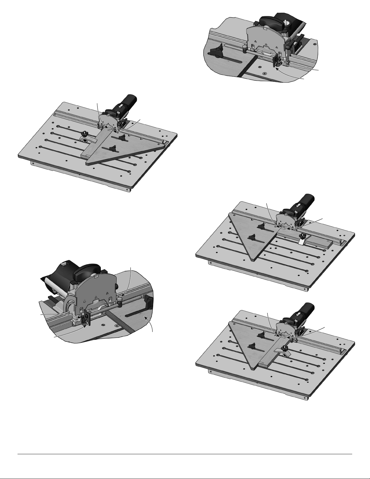
9. Lorsque la mortaise de gauche est fraisée sur les quatre
pièces, insérer la pige de réglage dans le guide coulissant et
appuyer son talon contre la butée rétractable la plus éloignée
sur la fraiseuse.
10. Bloquer le réglage de la pige, retirer celle-ci du guide
coulissant et la mettre de côté.
Remarque : L’avant de la fraiseuse Domino comporte plusieurs
éléments pouvant servir de point de référence pour les réglages.
Il est bon de toujours employer le même point de référence. Dans
cet exemple, le point de référence choisi est le côté intérieur de
la butée rétractable la plus éloignée.
11. Repositionner le guide coulissant du côté droit de la
fraiseuse et insérer la pige de réglage dans le trou du guide.
12. Faire glisser le guide jusqu’à ce que le talon de la pige
de réglage s’appuie contre le côté intérieur de la butée
rétractable la plus éloignée.
13. Veiller à ce que le guide coulissant s’appuie bien contre le
guide fixe. Serrer le guide coulissant en place avec les
poignées à 3 branches.
14. Retirer la pige de réglage.
15. Faire un test avec une pièce de rebut du cadre pour vérifier
la précision du réglage et pour s’assurer que les mortaises
correspondantes sont bien alignées.
16. Si tout convient, fraiser les mortaises droites des quatre pièces.
Dans le cas contraire, apporter les correctifs nécessaires.
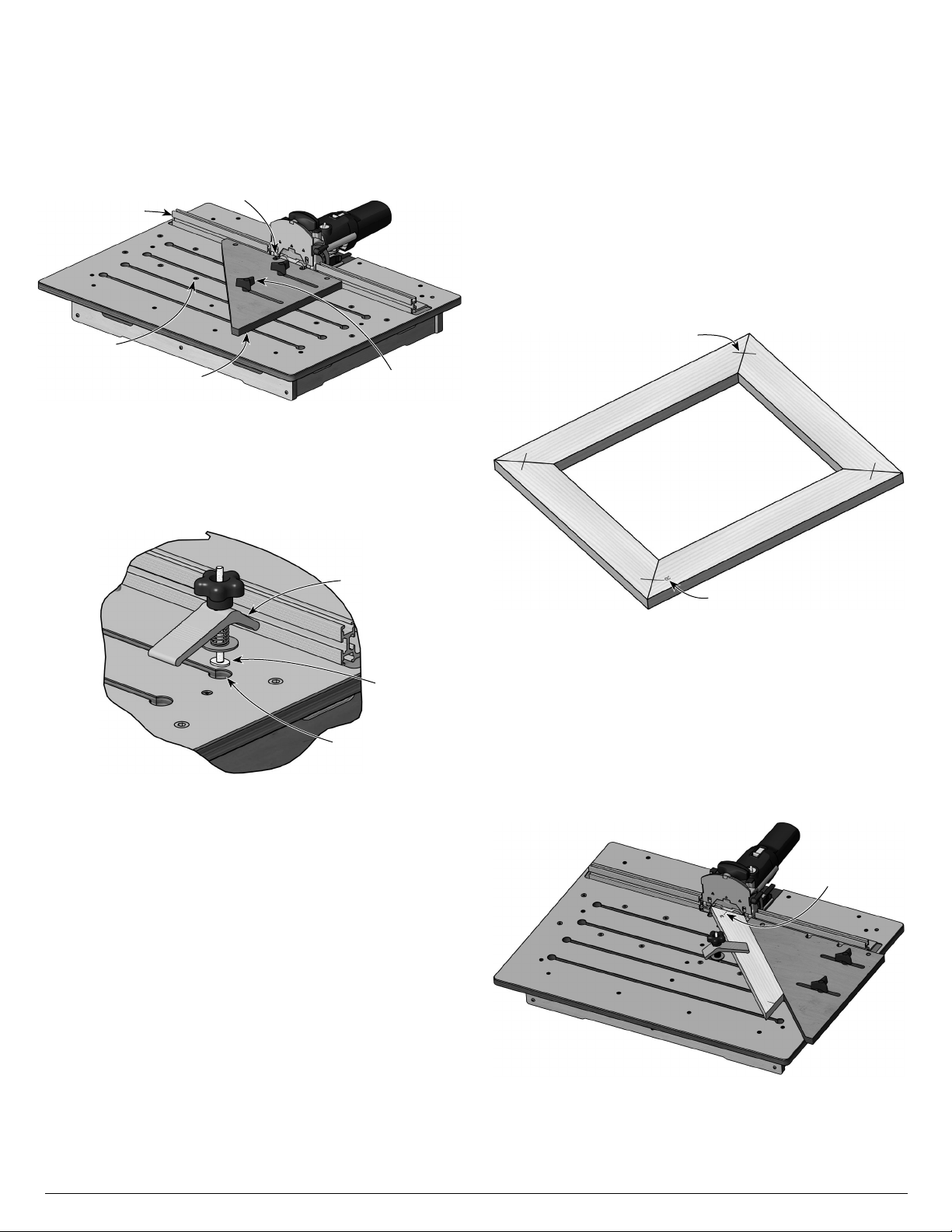
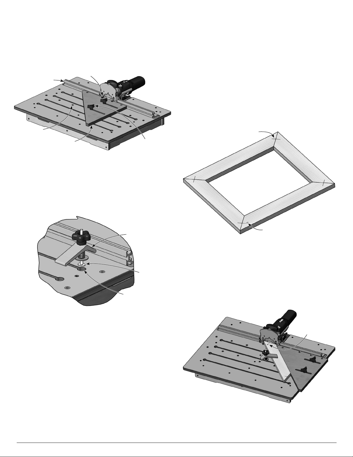
Fraisage d’un assemblage à angle droit
Assembler un cadre à angle droit requiert un peu plus d’attention,
car le marquage nécessite de bien distinguer le côté gauche du
côté droit d’une pièce.
Remarque : Dans tous les cas d’usinage mécanisé, il est bon
de disposer de pièces supplémentaires pour tester les réglages
initiaux. Cela est particulièrement important pour régler
l’installation avant d’usiner la seconde moitié des assemblages.
1. Couper toutes les pièces du cadre à la longueur voulue.
2. Placer les pièces pour former le cadre et marquer la position
des mortaises en plus d’indiquer le dessus et l’extérieur de
chaque pièce. Dans cet exemple, la position des mortaises
est marquée d’une double ligne chevauchant les joints et
parallèle à l’extérieur du cadre. De chaque côté de cette
double ligne, une ligne perpendiculaire indique le côté
extérieur du cadre.
3. Sur au moins un des joints, il faut marquer avec précision le
centre de la mortaise. Bien identifier cette marque de
référence, par exemple à l’aide d’une lettre R. Cette marque
de référence servira au réglage de la table d’usinage.
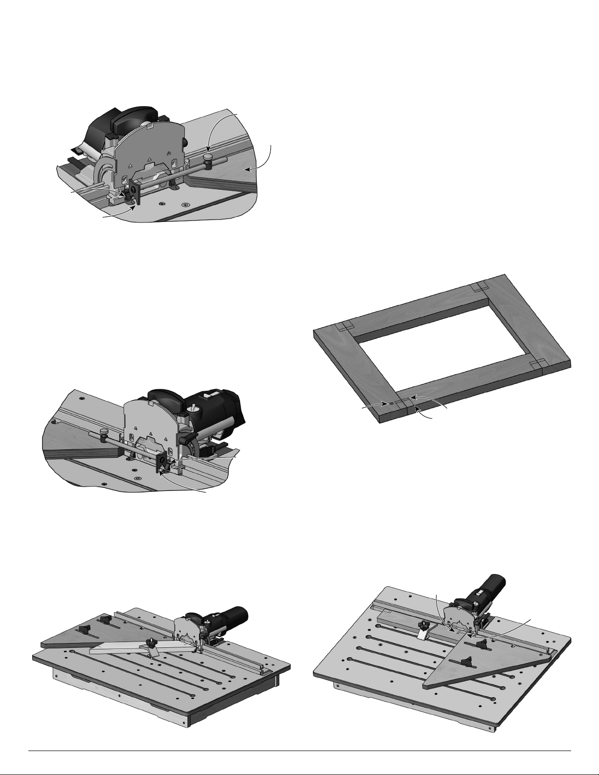
4. Prendre la pièce spécifiquement marquée pour le réglage
initial et aligner la marque de référence avec le repère
central gravé sur la fraiseuse.
5. Bien appuyer la pièce contre le guide fixe et l’immobiliser
avec au moins une serre de retenue.
6. Appuyer le guide coulissant contre le bout de la pièce
marqué comme étant l’extérieur du cadre, en veillant aussi à
bien l’appuyer contre le guide fixe. Immobiliser le guide
coulissant en serrant les poignées à 3 branches.
Figure 16 : Fraisage des mortaises opposées
Figure 14 : Ajustement de la pige de réglage
Butée
rétractable
Pige de
réglage
Talon
Guide
coulissant
Figure 15 : Ajustement de la position inversée du guide coulissant
avec la pige de réglage
Butée
rétractable la
plus éloignée
Talon
Figure 17 : Cadre assemblé à angle droit avec l’emplacement
des mortaises marqué d’une ligne double et l’extérieur du cadre
marqué d’une ligne simple
Marque de
référence Marque de mortaise
Marque du côté extérieur
Figure 18 : Fraisage de la première mortaise sur chant
Marque de
référence Marque extérieure
contre le guide
coulissant
4