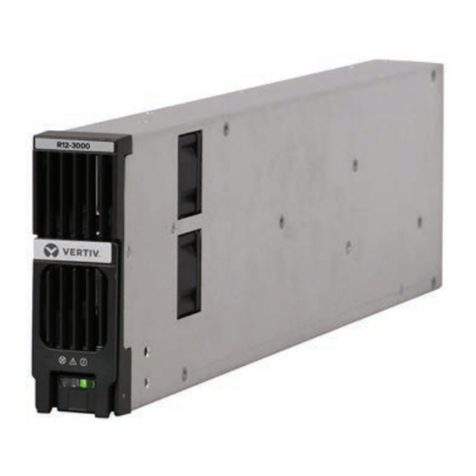
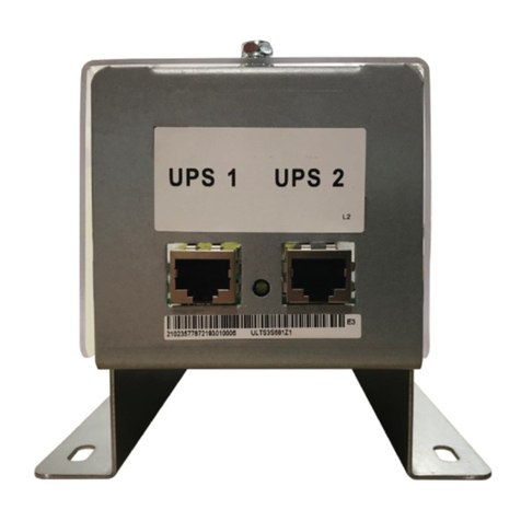
Vertiv NetSure 559251 User manual

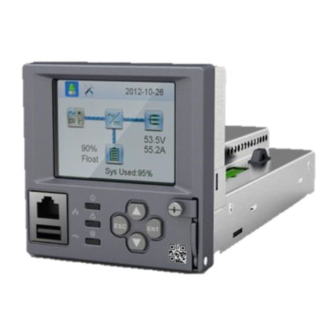
NetSure™ Control Unit (NCU) Controller
2nd Ethernet Port Retrofit Kit
Installation Manual
Kit Specification Number: 559251
For Use in Spec. No. 582127000 and 581127000 Power Systems

Vertiv™ NetSure™ Control Unit (NCU) Controller 2nd Ethernet Port Retrofit Kit Installation Manual
The information contained in this document is subject to change without
notice and may not be suitable for all applications. While every precaution has
been taken to ensure the accuracy and completeness of this document, Vertiv
assumes no responsibility and disclaims all liability for damages resulting from
use of this information or for any errors or omissions. Refer to other local
practices or building codes as applicable for the correct methods, tools, and
materials to be used in performing procedures not specifically described in
this document.
The products covered by this instruction manual are manufactured and/or
sold by Vertiv. This document is the property of Vertiv and contains
confidential and proprietary information owned by Vertiv. Any copying, use or
disclosure of it without the written permission of Vertiv is strictly prohibited.
Names of companies and products are trademarks or registered trademarks of
the respective companies. Any questions regarding usage of trademark
names should be directed to the original manufacturer.
Technical Support Site
If you encounter any installation or operational issues with your product, check the pertinent section of this
manual to see if the issue can be resolved by following outlined procedures.
Visit https://www.vertiv.com/en-us/support/ for additional assistance.

Vertiv™ NetSure™ Control Unit (NCU) Controller 2nd Ethernet Port Retrofit Kit Installation Manual
Proprietary and Confidential © 2022 Vertiv Group Corp.
iii
TABLE OF CONTENTS
Admonishments Used in this Document......................................................................................................................... iv
Important Safety Instructions ............................................................................................................................................. v
Safety Admonishments Definitions..........................................................................................................................................................................................................................v
Safety and Regulatory Statements...........................................................................................................................................................................................................................v
Déclarations de Sécurité et de Réglementation...........................................................................................................................................................................................v
1Vertiv™ NetSure™ Control Unit (NCU) Controller 2nd Ethernet Port Retrofit Kit ........................................ 1
1.1 Kit Description..................................................................................................................................................................................................................................................................1
1.2 Kit Contents .......................................................................................................................................................................................................................................................................2
1.3 Tools and Material Required..............................................................................................................................................................................................................................2
1.4 Installation Procedure...............................................................................................................................................................................................................................................2
2Vertiv™ NetSure™ Control Unit (NCU) Controller Second Ethernet Port Connection ............................... 7

Vertiv™ NetSure™ Control Unit (NCU) Controller 2nd Ethernet Port Retrofit Kit Installation Manual
Proprietary and Confidential © 2022 Vertiv Group Corp.
iv
Admonishments Used in this Document
DANGER
! Warns of a hazard the reader
will
be exposed to that will
likely
result
in death or serious injury if not avoided. (ANSI, OSHA)
WARNING
! Warns of a potential hazard the reader
may
be exposed to that
could
result in
death or serious injury if not avoided. This admonition is not used for situations that pose a
risk o
nly to equipment, software, data, or service. (ANSI)
CAUTION
! Warns of a potential hazard the reader
may
be exposed to that
could
result in minor or moderate injury if not avoided. (ANSI, OSHA) This admonition is not
used for situations that pose a risk only to equipment, data, or service, even if such use
appears to be permitted in some of the applicable standards. (OSHA)
ALERT
! Alerts the reader to an action that
must be avoided
in order to protect
equipment, software, data, or service. (ISO)
ALERT
! Alerts the reader to an action that
must be performed
in order to prevent
equipment damage, software corruption, data lo
ss, or service interruption. (ISO)
FIRE SAFETY
! Informs the reader of fire safety information, reminders, precautions,
or policies, or of the locations of fire
-fighting and fire-safety equipment. (ISO)
SAFETY
! Informs the reader of general safety information, reminders, precautions, or
policies not related to a particular source of hazard or to fire safety. (ISO, ANSI, OSHA)

Vertiv™ NetSure™ Control Unit (NCU) Controller 2nd Ethernet Port Retrofit Kit Installation Manual
Proprietary and Confidential © 2022 Vertiv Group Corp.
v
Important Safety Instructions
Safety Admonishments Definitions
Definitions of the safety admonishments used in this document are listed under “Admonishments Used in this Document” on page iv.
Safety and Regulatory Statements
Refer to Section 4154 (provided with your customer documentation) for Safety and Regulatory Statements.
Déclarations de Sécurité et de Réglementation
Reportez-vous à la Section 4154 (fourni avec les documents de votre client) pour les déclarations de sécurité et de réglementation.

Vertiv™ NetSure™ Control Unit (NCU) Controller 2nd Ethernet Port Retrofit Kit Installation Manual
Proprietary and Confidential © 2022 Vertiv Group Corp.
vi
This page intentionally left blank.

Vertiv™ NetSure™ Control Unit (NCU) Controller 2nd Ethernet Port Retrofit Kit Installation Manual
Proprietary and Confidential © 2022 Vertiv Group Corp.
1
1Vertiv™ NetSure™ Control Unit (NCU) Controller 2nd
Ethernet Port Retrofit Kit
1.1 Kit Description
These instructions provide a step-by-step procedure to field install this kit into Power System Spec. No. 582127000 and 581127000.
Installation of this kit in other equipment should not be attempted.
This kit provides a complete control module assembly that allows an IB4 board to be connected to the NCU Controller in an older
main bay. This kit provides the IB4 board with a second Ethernet port. The Ethernet port located on the NCU Controller’s front panel
can be used to connect a computer directly to the NCU. The Ethernet port located on the IB4 board can be used to connect the NCU
Controller to your Local Area Network (LAN).
There are two kits available. One to add the IB4 board to a newer style main bay that provides an NCU Controller motherboard
connector for an IB4 board cable and the other for an older style main bay that does not have this NCU Controller motherboard
connector. THIS KIT IS FOR A MAIN BAY THAT DOES NOT HAVE AN IB4 BOARD CONNECTOR LOCATED ON THE NCU
MOTHERBOARD. See Figure 1.1 for identification.
Figure 1.1 Identifying Control Module Assembly IB4 Board Connector

Vertiv™ NetSure™ Control Unit (NCU) Controller 2nd Ethernet Port Retrofit Kit Installation Manual
Proprietary and Confidential © 2022 Vertiv Group Corp.
2
1.2 Kit Contents
Table 1.1 lists the items furnished with this kit. Before starting the procedure, check the items furnished against those listed to ensure
that there are no shortages.
Table 1.1 Kit Contents
Qty. Description P/N
1 Preassembled
Control Module Assembly 559240
1 IB4 Board Assembly 559239
1 IB4 Board USB Cable 559324
1 LVD Inhibit Label 548124
1 Battery Disconnect Label 548131
NOTE!
The system must be equipped with the NCU controller (model 1M830DNA) for the second Ethernet port to operate.
If the system is equipped with the ACU+ controller (model 1M820DNA) it must be replaced by the NCU controller, which is
not provided with this kit and must be ordered separately.
1.3 Tools and Material Required
Table 1.2 lists the items required to install this kit.
Table 1.2 Tools and Material Required
Description
Cross-Blade Screwdriver
Standard Socket Set
1.4 Installation Procedure
THESE INSTRUCTIONS SHOULD BE READ THROUGH COMPLETELY BEFORE INSTALLING THE KIT.
The following is a step-by-step procedure to install the kit. The procedure has been written for ease of use and to minimize the
possibility of contact with potentially hazardous energy. This procedure should be performed in the sequence given, and each step
should be completely read and fully understood before performing that step. Observe all “Important Safety Instructions” presented at
the beginning of this document as this procedure is being performed. As each step of the procedure is completed, the box adjacent
to the respective step should be checked. This will minimize the possibility of inadvertently skipping any steps. If the step is not
required to be performed for your site, also check the box to indicate that it was read.
NOTE!
When performing any step in this procedure which requires removal of existing hardware, retain all hardware for use
in subsequent steps, unless otherwise stated.
1.4.1 Procedure
DANGER! Observe the Important Safety Instructions located at the beginning of this document.
NOTE!
Refer to Figure 1.1 Figure 1.2, Figure 1.3, and Figure 1.4 as this procedure is performed.

Vertiv™ NetSure™ Control Unit (NCU) Controller 2nd Ethernet Port Retrofit Kit Installation Manual
Proprietary and Confidential © 2022 Vertiv Group Corp.
3
Removing the Existing Control Module Assembly
[ ] 1. Remove the NCU Controller from the system. Set the NCU Controller aside. It will be re-used.
[ ] 2. Locate the cables connected to the existing control module assembly. Note that the top of the control module assembly
may have to be removed to access some cables. These cables will be disconnected. Label the cables so they can be re-
connected to the proper connectors. See Figure 1.2.
[ ] 3. Remove all cables from the existing control module assembly.
[ ] 4. If the existing control module assembly contains the optional LVD Driver Circuit Card, optional LVD Driver Lite Circuit
Card, and/or the optional Manual Battery Disconnect Circuit Card, these assemblies must be removed from the existing
control module assembly and mounted into the kit supplied control module assembly. Refer to Figure 1.2 and transfer
any of these assemblies from the existing control module assembly to the kit supplied control module assembly.
[ ] 5. Remove the existing control module assembly by removing the two (2) screws securing the front of the assembly to the
distribution cabinet floor. Slide the assembly forward and up to remove it from the distribution cabinet. See Figure 1.3.
[ ] 6. Set the existing control module assembly aside. It will not be re-used.
Installing the Kit Supplied Control Module Assembly
[ ] 1. Install the kit supplied control module assembly by sliding it into the distribution cabinet, ensuring the assembly’s base is
inserted under the tabs located on the distribution cabinet floor (at the rear). Secure the control module assembly to
the distribution cabinet floor using the two (2) screws removed from the existing control module assembly. See
Figure 1.3.
[ ] 2. Re-connect the cables to the kit supplied control module assembly as they were connected to the existing control
module assembly. See Figure 1.2.
[ ] 3. If the existing control module assembly contained the optional LVD Driver Circuit Card, optional LVD Driver Lite Circuit
Card, and/or the optional Manual Battery Disconnect Circuit Card, adhere the kit provided label(s) to the front of the kit
supplied control module assembly as required.
[ ] 4. Re-install the NCU Controller into the control module assembly.
Installing the Kit Supplied IB4 Board
[ ] 1. Locate the two (2) cable lacing holders at the top of the distribution cabinet. Remove these cable lacing holders. See
Figure 1.4.
[ ] 2. Remove the hardware from the kit supplied IB4 board assembly mounting bracket. Orient the kit supplied IB4 board
assembly (with mounting bracket) over the holes that the cable lacing holders were removed from, as shown in
Figure 1.4. Secure the IB4 board mounting bracket to the distribution cabinet with the hardware just removed. See
Figure 1.4.
[ ] 3. Attach the provided IB4 board cable to the IB4 board. Route the cable along existing cables to the back of the control
module assembly. Plug the cable into the appropriate connector located on the back of the control module assembly.
See Figure 1.1 and Figure 1.4.
Vertiv™ NetSure™ Control Unit (NCU) Controller 2nd Ethernet Port Retrofit Kit Installation Manual
Proprietary and Confidential © 2022 Vertiv Group Corp.
4
Figure 1.2 Installing the Kit (Removing / Replacing Cables)

Vertiv™ NetSure™ Control Unit (NCU) Controller 2nd Ethernet Port Retrofit Kit Installation Manual
Proprietary and Confidential © 2022 Vertiv Group Corp.
5
Figure 1.3 Installing the Kit (Control Module Assembly)

Vertiv™ NetSure™ Control Unit (NCU) Controller 2nd Ethernet Port Retrofit Kit Installation Manual
Proprietary and Confidential © 2022 Vertiv Group Corp.
6
Figure 1.4 Installing the Kit (IB4 Board Assembly)

Vertiv™ NetSure™ Control Unit (NCU) Controller 2nd Ethernet Port Retrofit Kit Installation Manual
Proprietary and Confidential © 2022 Vertiv Group Corp.
7
2Vertiv™ NetSure™ Control Unit (NCU) Controller Second
Ethernet Port Connection
You just installed the IB4 board and connected it to the NCU Controller backplane via the kit furnished cable. The IB4 board provides
a second Ethernet port. The Ethernet port located on the NCU Controller’s front panel can ONLY be used to connect a computer
directly to the NCU. The Ethernet port located on the IB4 board can be used to connect the NCU Controller to your Local Area
Network (LAN).
NOTE!
If your system has an IB4 board, DO NOT connect your Local Area Network (LAN) to the NCU front Ethernet port.
NOTE!
Refer to the NCU Controller User Manual (UM1M830BNA) for instructions on using the controller’s Ethernet
connections.
An RJ-45 10BaseT jack is provided on the IB4 board for connection into a customer's network. This jack has a standard Ethernet pin
configuration scheme, twisted pair. Refer to Figure 2.1 for location. Use shielded Ethernet cable (grounded at both ends). Note that
the IB4 board’s RJ-45 jack is connected to chassis ground. Refer to the NCU Controller Instructions (UM1M830BNA) for operational
details.
WARNING! The intra-building port(s) of the equipment or subassembly is suitable for connection to intra-building or
unexposed wiring or cabling only. The intra-building port(s) of the equipment or subassembly MUST NOT be metallically
connected to the interfaces that connect to the OSP or its wiring. These interfaces are designed for use as intra-building
interfaces only (Type 2 or Type 4 ports as described in GR-1089-CORE, Issue 4) and require isolation from the exposed OSP
cabling. The addition of Primary Protectors is not sufficient protection in order to connect these interfaces metallically to
OSP wiring.
The intra-building port (RJ-45) of the equipment or subassembly must use shielded intra-building cabling/wiring that is
grounded at both ends.

Vertiv™ NetSure™ Control Unit (NCU) Controller 2nd Ethernet Port Retrofit Kit Installation Manual
Proprietary and Confidential © 2022 Vertiv Group Corp.
8
Figure 2.1 IB4 Board NCU Controller Second Ethernet Port Connection

Vertiv™ NetSure™ Control Unit (NCU) Controller 2nd Ethernet Port Retrofit Kit Installation Manual
Proprietary and Confidential © 2022 Vertiv Group Corp.
Connect with Vertiv on Social Media
https://www.facebook.com/vertivI
https://www.instagram.com/vertiv/
https://www.linkedin.com/company/vertiv/
https://www.twitter.com/vertiv/

Vertiv.com | Vertiv Headquarters, 1050 Dearborn Drive, Columbus, OH, 43085, USA
© 2022 Vertiv Group Corp. All rights reserved. Vertiv™ and the Vertiv logo are trademarks or registered trademarks of Vertiv Group
Corp. All other names and logos referred to are trade names, trademarks or registered trademarks of their respective owners. While
every precaution has been taken to ensure accuracy and completeness here, Vertiv Group Corp. assumes no responsibility, and
disclaims all liability, for damages resulting from use of this information or for any errors or omissions. Specifications, rebates and
other promotional offers are subject to change at Vertiv’s sole discretion upon notice.
IM559251_REVE
Proprietary and Confidential © 2022 Vertiv Group Corp.
Table of contents
Other Vertiv Controllers manuals

Vertiv
Vertiv Liebert AC8 User manual

Vertiv
Vertiv Liebert Load Bus Sync Controller User manual

Vertiv
Vertiv NetSure 802 Series User manual

Vertiv
Vertiv Liebert EXL 31 Installation and maintenance instructions

Vertiv
Vertiv M830B User manual

Vertiv
Vertiv NetSure SCC User manual

Vertiv
Vertiv Liqui-tect LP6000 Installation and maintenance instructions

Vertiv
Vertiv Netsure User manual

Vertiv
Vertiv Liebert AC8 User manual