Vertiv AVOCENT LONGVIEW 3010 User manual

AVOCENT® LONGVIEW™ SERIES
HIGH PERFORMANCE KVM EXTENDER SYSTEMS
Quick Installation Guide
590-1516-501A 1
The LongView™ high performance KVM
extender system provides the fastest way
to extend high-quality video, audio and
USB data across your network.
Transmitter and receiver extenders can
be configured in a single or dual-user
configuration to best meet the needs of
your system. Configuration options are
illustrated on the right, and general
system information is provided in the
following section. Proceed to the next
page for installation instructions.
Supported Hardware
LongView™ 3010 and 3020 extenders
support most standard speakers/
headsets, microphones and USB
keyboards and mice. While both extender
versions provide dual stereo audio, the
LongView™ 3020 extenders also provide
an additional video channel. Each receiver
extender provides four USB outlets that
can individually support USB 2.0
peripherals at speeds of up to 12 Mbps.
The USB connections are seamless to
ensure that all four full-speed USB 2.0
devices can be used simultaneously with
full support for a disconnect/re-connect
at any time without causing any errors in
the system.
Video and Audio Features
The LongView extender system provides
CD quality sound and high video
resolutions of up to 1920 x 1200. The
system supports the Display Data Channel
(DDC) scheme, allowing video display
capabilities to be optimized by a computer
video adaptor. All receiver extenders also
provide Video Compensation Mode for
configuration of cable types and lengths,
video gains and color skew. Three
equalization bands within the receiver
extenders ensure that a sharp video
image is received every time.
CAT x cable
Audio
USB
Video
1
USER 1
CAT x link (up to 300m)
LongView™ Extender Dual-user Configuration
CAT x link (up to 300 m)
Video and audio crosslinks
are made from first
transmitter module to the
second transmitter module
Both transmitter modules
require their own USB links
to the computer
TRANSMITTER
1
USER 2
LongView™ Extender Single-user Configuration
Up to 300 meters separation
Additional CAT x
link
Additional video
channel and dual stereo
audio channels
Receiver
Extender
Transmitter
Extender
TRANSMITTER
2
RECEIVER
2
RECEIVER
1

AVOCENT® LONGVIEW™ 3000 SERIES HIGH PERFORMANCE KVM EXTENDER SYSTEMS
Quick Installation Guide
2 590-1516-501A
Cable Extension Rules
Use the following table to
determine the appropriate cable type to
support the distance of your
configuration.
Maximum Cable Length
CAT5 / CAT5e 250 m
CAT6 / CAT7 300 m
CAT7a Patch 200 m
Installation
Instructions apply for both modules
unless referenced specifically.
NOTE: Prior to the following steps,
ensure your computer is turned o.
1. Connecting transmitter
extender video
For the LongView™ 3010 extender,
connect a video cable from the
computer to the video port on the
left end of the extender.
For the LongView™ 3020 extender,
connect the video cable from the
primary video port on the computer
to the bottom (primary) video port
on the left end of the extender.
Then, connect the cable from
the secondary video port on
the computer to the top
(secondary) video port on the
left end of the extender.
2. Connecting other transmitter
extender peripherals
The LongView 3010 transmitter
extender is designed to be powered
on the right end of the extender via
a USB connection from the
computer (see step 5).
If this is not possible, the USB port
on the left end of the extender can
be used for a USB device.
To connect a USB device to the left
end of a LongView 3010 or 3020
extender, use a cable no longer than
three meters and plug the USB
connector into the designated
transmitter port. Connect the other
end to a USB computer port.
LongView™ Extender Left End Configuration (Transmitter)
LongView™ 3010 Extender
LongView™ 3020 Extender
LongView™ Extender Left End Configuration (Transmitter)
Secondary
Primary
1
1
2
2

AVOCENT® LONGVIEW™ 3000 SERIES HIGH PERFORMANCE KVM EXTENDER SYSTEMS
Quick Installation Guide
3 590-1516-501A
NOTE: Although the
LongView™ extender system
may be used with other USB
hubs in the system, due to
power constraints, do not connect
the transmitter extender to the
downstream port of a bus-powered
USB hub. Also, LongView™ 3020
transmitter extenders must always
be powered via the supplied power
adaptor.
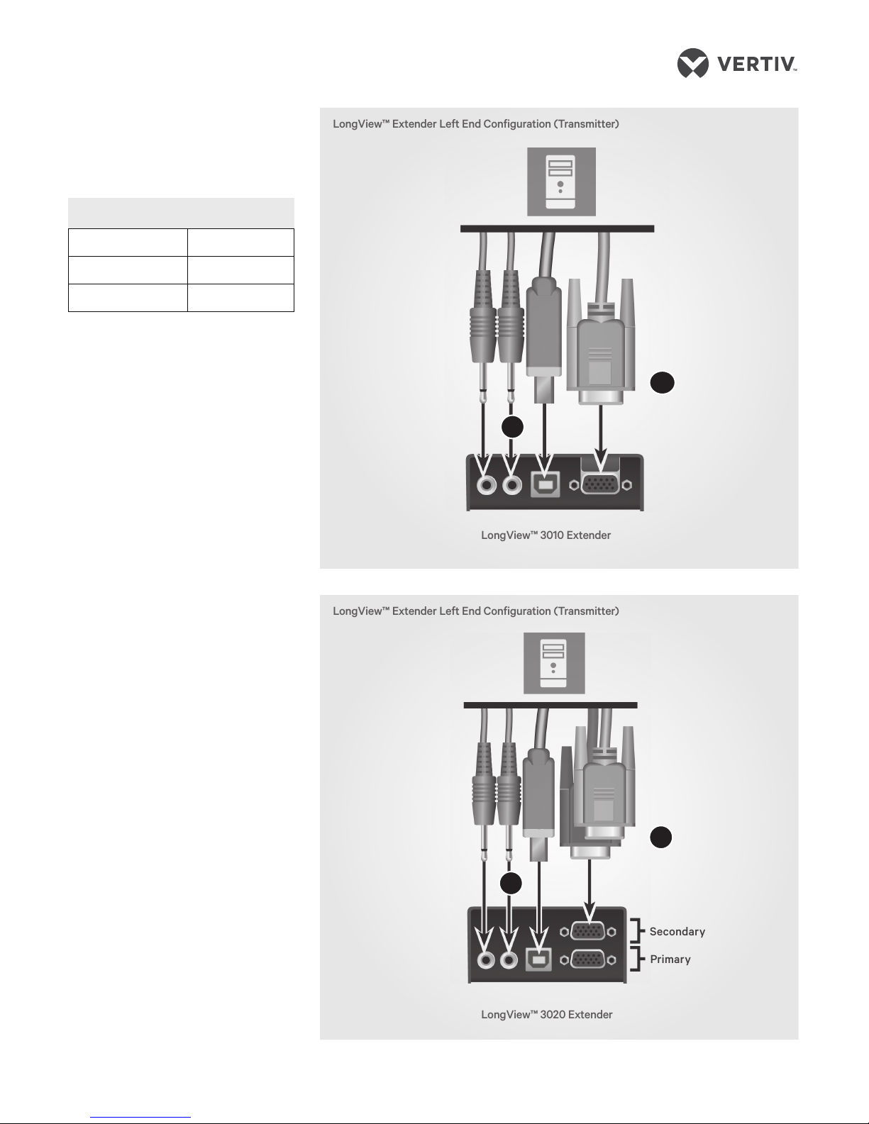
While audio is usually connected to
the receiver extender (see step 9), if
you wish to use the optional speaker
connections on the transmitter
extender, attach the cables to the
appropriately labeled ports on the
left end.
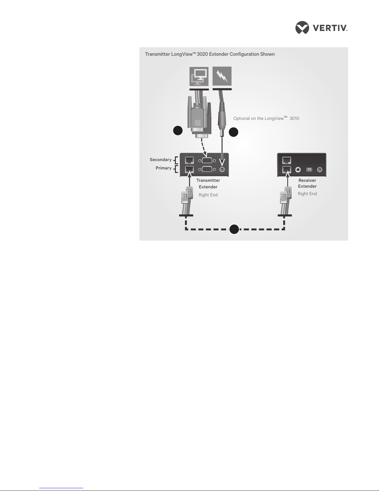
3. Connecting the transmitter
extender to the receiver
extender
On the right end of your
extender model, insert one end of a
CAT cable into the TO RECEIVER
port on the transmitter extender and
the other end into the TO
TRANSMITTER port on the receiver
extender.
If you are using the LongView
3020 extenders, the initial
connection is made between the
bottom ports on the transmitter and
receiver extenders. If you choose to
make a secondary connection on
the LongView 3020 extender, that
connection is between the top ports.
4. (Optional) Connecting an
additional video monitor to
the transmitter extender in a
single-user configuration
NOTE: If you plan to use a dual-
user configuration, skip this step.
If you wish to add a transmitter
monitor directly to the transmitter
extender, connect the video cable
between monitor and the OUT video
port on the right side of the
transmitter extender.
For LongView 3020 extenders,
the initial connection should be
made from the bottom
(primary) extender port and an
additional connection should
be from the top (secondary)
extender port.
5. Connecting transmitter
extender power
For the LongView™ 3010 extender,
use a cable no longer than three
meters and plug the USB connector
into the designated transmitter
extender port on the right end.
Connect the other end to a USB
computer port with high power
output.
NOTE: If your computer does not
have a high power output for the USB
port, the LongView 3010 extender
must be powered with an optional
power adaptor. Contact your sales
representative for more information.
If you are using a LongView 3020
extender (or the LongView 3010
optional power adaptor), assemble
the power adaptor and the power
cord. Insert one end of the power
cord into the transmitter extender
and plug the other end into an
appropriate power source.
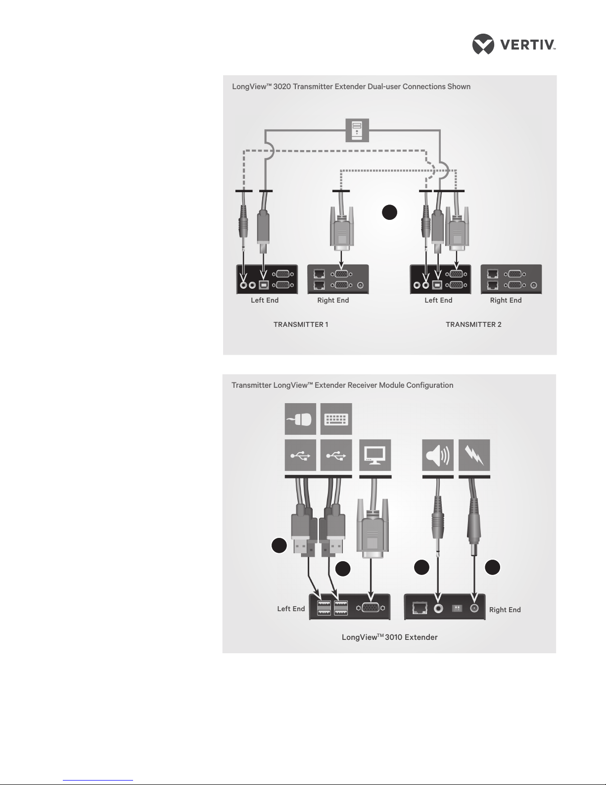
6. (Optional) Expanding
your system to a dual-
user configuration
In a dual-user configuration, a
single computer is controlled from
two transmitter extenders
(Transmitter 1 and Transmitter 2).
Each extender receives the same
audio and video output and also has
equal concurrent control over the
computer. General installation is
already complete for Transmitter 1 if
you have completed steps 1-5.
NOTE: Arbitration between
extenders is handled via a
computer USB system, so this
configuration is best suited for
users not required to frequently
have simultaneous access.
To connect video to Transmitter 2,
insert one end of a video cable into
the video port on the left side of the
Transmitter 2 extender. Plug the other
end into the video port on the right
side of the Transmitter 1 extender.
Transmitter LongView™ 3020 Extender Configuration Shown
Secondary
Primary
Transmitter
Extender
Right End
Receiver
Extender
Right End
Optional on the LongView™3010
4
3
5

AVOCENT® LONGVIEW™ 3000 SERIES HIGH PERFORMANCE KVM EXTENDER SYSTEMS
Quick Installation Guide
4 590-1516-501A
NOTE: For LongView™ 3020
extenders, the initial connection
should be made between the
bottom (primary) extender ports and
any additional connections should
be from the top (secondary)
extender ports.
For both extender models,
establish the USB connection
to the computer by using a
cable no longer than three
meters to plug the USB connector
into the Transmitter 2 extender USB
port and connect the other end to a
USB computer port. Connect an
audio cable from the OUT audio port
on the left side of the Transmitter 1
extender to the IN audio port on the
left side of the Transmitter 2
extender. Repeat step 3 to connect
the Transmitter 2 to a receiver
extender, then repeat step 5 to
connect the transmitter extender
power.
7. Connecting receiver extender
video
On the left end of the receiver
LongView™ 3010 extender, connect
a video cable from your monitor to
the video port on the extender.
On the left end of the receiver
LongView 3020 extender,
connect the cable from the
video port on a monitor to the
bottom (primary) video port on
the extender. Then, connect the
cable from an additional video
port on a monitor computer to
the top (secondary) video port
on the extender.
8. Connecting the keyboard and
mouse
For either model, plug one end
of the keyboard and mouse
connectors into USB ports on the
left end of the receiver extender and
plug the other ends into USB
computer ports. The extender
system allows up to four USB
devices to be connected at one time.
NOTE:
Ensure the total power
requirements of the connected
USB devices does not exceed
1.7 A, preferably with a
maximum allowable current
draw of .5 A per device. Each
extender contains a self-resetting
fuse that will shut the extender
down to prevent damage if the total
power draw is excessive.
TRANSMITTER 1 TRANSMITTER 2
Left End Right End Left End Right End
LongView™ 3020 Transmitter Extender Dual-user Connections Shown
Transmitter LongView™ Extender Receiver Module Configuration
Left End
LongViewTM 3010 Extender
Right End
6
8
7910

AVOCENT® LONGVIEW™ 3000 SERIES HIGH PERFORMANCE KVM EXTENDER SYSTEMS
Quick Installation Guide
5 590-1516-501A
9. Connecting audio
On the right end of the receiver
extender for both models,
attach the speaker and
microphone cables to the
appropriately labeled ports.
10. Connecting receiver extender
power
For both models, assemble the
power adaptor and the power
cord. Insert one end of the
power cord into the POWER
port on the right end of the receiver
extender and plug the other end into
an appropriate power source.
11. Powering the extender
system (either model)
NOTE:
If you plan to use a dual-user
configuration, ensure steps 7-11 are
completed for both receiver
extenders.
Turn on the monitor and the receiver
extender. If the transmitter extender
is not powered by the computer, turn
it on next.
When you turn on the transmitter
extender, observe the green
LED lighting pattern on the
right side of the extender. Then,
turn on the computer.
Verifying transmitter extender
video data
It is not possible for video display
data to be transmitted from the monitor
at a receiver extender across the
transmitter extender and then to the
computer video adaptor. To compensate
for this, the LongView™ extender system
uses a DDC scheme to prompt a
transmitter extender to read and store
the data from the receiver monitor and
share it with the computer as needed.
This DDC data search takes place at the
transmitter extender video out port
when the extender is turned on and
status is shown via LEDs on the TO
RECEIVER port.
NOTE: Dual video channels are handled
separately for LongView™ 3020
extenders. If you wish to capture DDC
data from both receiver monitors,
temporarily connect both monitors to the
Video Out ports on the transmitter
extender.
When you turn on the transmitter
extender, a green LED will flash
once to indicate that data is being
read. If the information matches what is
already stored on the transmitter
extender, normal extender
operation resumes. If the
information is dierent, the green
LED will flash rapidly as new
information is stored. A single flash
after that indicates that normal
operation will resume.
LED Flashing Indications
• Two flashes: indicates a
checksum error and no
information is programmed
• Three flashes: indicates too much
data to fit into the extender; the
extender holds no more than two
pages of DDC data
• Rapid flashing, then four flashes:
indicates data was lost during
copying and default data was
substituted; power cycle the
transmitter extender
• Rapid flashing, then five flashes:
indicates a checksum error
during copying and default data
was substituted; power cycle the
transmitter extender
Adjusting Receiver Extender
Video Quality
LongView receiver extenders contain a
video compensation system that allows
you to delay or advance timing of color
signals so that they arrive at the video
monitor at the correct times and
provide an optimal display of video
content. Receiver extenders feature a
miniature switch to enable Video
Compensation Mode. When you enable
this mode by moving miniature switch 1
to the ON position, the Num Lock, Caps
Lock and Scroll Lock keys on the USB
keyboard at the receiver extender will
flash in sequence. A green LED located
on the TO TRANSMITTER port on the
receiver extender will also flash.
Transmitter LongView™ Extender Receiver Module Configuration
LongViewTM 3020 Extender
Left End Right End
8
7910

AVOCENT® LONGVIEW™ 3000 SERIES HIGH PERFORMANCE KVM EXTENDER SYSTEMS
Quick Installation Guide
6 590-1516-501A
NOTE: During Video Compensation
Mode, all connected USB devices are
temporarily isolated from the computer.
The key flashing sequence
indicates Standby level within
Video Compensation mode. From
this level, set the cable types and
lengths, then use the video gain
and color skew adjustments to fine-tune
the receiver video image.
See the Video Compensation
Adjustments table on the following
page for more information.
Move miniature switch 1 on the
receiver
extender to the o position to exit this
mode. All USB devices are then
reconnected and normal operations
resume.

AVOCENT® LONGVIEW™ 3000 SERIES HIGH PERFORMANCE KVM EXTENDER SYSTEMS
Quick Installation Guide
7 590-1516-501A
Video Compensation Adjustments Table
Adjustment To
Activate
Flashing
Indicators Description
Video Compensation
Changes to each LongView™
3020 extender channel
separately
Press HAlternate flashing
between Num
Lock and Scroll
Lock, then Caps
Lock
Press 1or 2to select the primary or secondary
video display. Make any compensation changes
indicated in this table, then press Hand 0. The green
LEDs on your receiver extender will flash.
Set Cable Type Press CNum Lock and
Caps Lock
Press the number that corresponds to the
category of cable used:
• Press 1for CAT5
• Press 2for CAT5e
• Press 3for CAT6
• Press 4for CAT7
• Press 5for CAT7a.
Press Enter to save or Esc to discard and return
to standby.
Set Cable Length Press LCaps Lock and
Scroll Lock
Use the keyboard to enter the cable length in
meters. Use the Up Arrow or Down Arrow keys
to increase/decrease the setting. Press Home to
return to a neutral setting. Press Enter to save or
Esc to discard and return to standby.
Change Video Gain
Level
Press the
Left Arrow
or Right
Arrow key
n/a The arrow keys enable you to increase or
decrease the setting. Press Home to return to a
neutral setting. Gain adjustments are saved
automatically.
Fix color skew Press R, G
or B
Num Lock (Red),
Caps Lock (Green),
Scroll Lock (Blue)
Use the Left Arrow or Right Arrow to adjust the
delay for chosen color. If the screen goes blank,
press the opposite Arrow key or press Home.
Press Enter to save or Esc to discard and return
to standby.

To contact Vertiv Technical Support: visit www.VertivCo.com
© 2017 Vertiv Co. All rights reserved. Vertiv and the Vertiv logo are trademarks or registered trademarks of Vertiv Co. All other names and logos referred to are trade names,
trademarks or registered trademarks of their respective owners. While every precaution has been taken to ensure accuracy and completeness herein, Vertiv Co. assumes no
responsibility, and disclaims all liability, for damages resulting from use of this information or for any errors or omissions. Specifications are subject to change without notice.
8 590-1516-501A
This manual suits for next models
1
Table of contents
Other Vertiv Extender manuals

Vertiv
Vertiv Avocent LV 5000 Series User manual

Vertiv
Vertiv AVOCENT HMX8000 User manual

Vertiv
Vertiv Avocent HMX Installation and maintenance instructions

Vertiv
Vertiv Avocent LongView 5500 User manual

Vertiv
Vertiv HMX3080T User manual

Vertiv
Vertiv AVOCENT LONGVIEW 5000 SERIES User manual

Vertiv
Vertiv AVOCENT LONGVIEW 4000 SERIES User manual

Vertiv
Vertiv Avocent LongView 5020P Installation and maintenance instructions

Vertiv
Vertiv AVOCENT HMX8000 User manual

Vertiv
Vertiv HMX3080T User manual