Vertiv Avocent LongView 5500 User manual

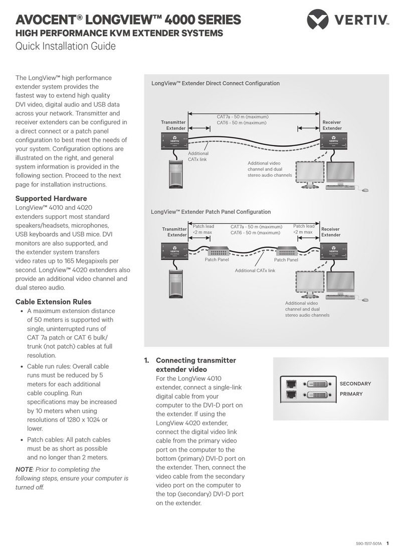
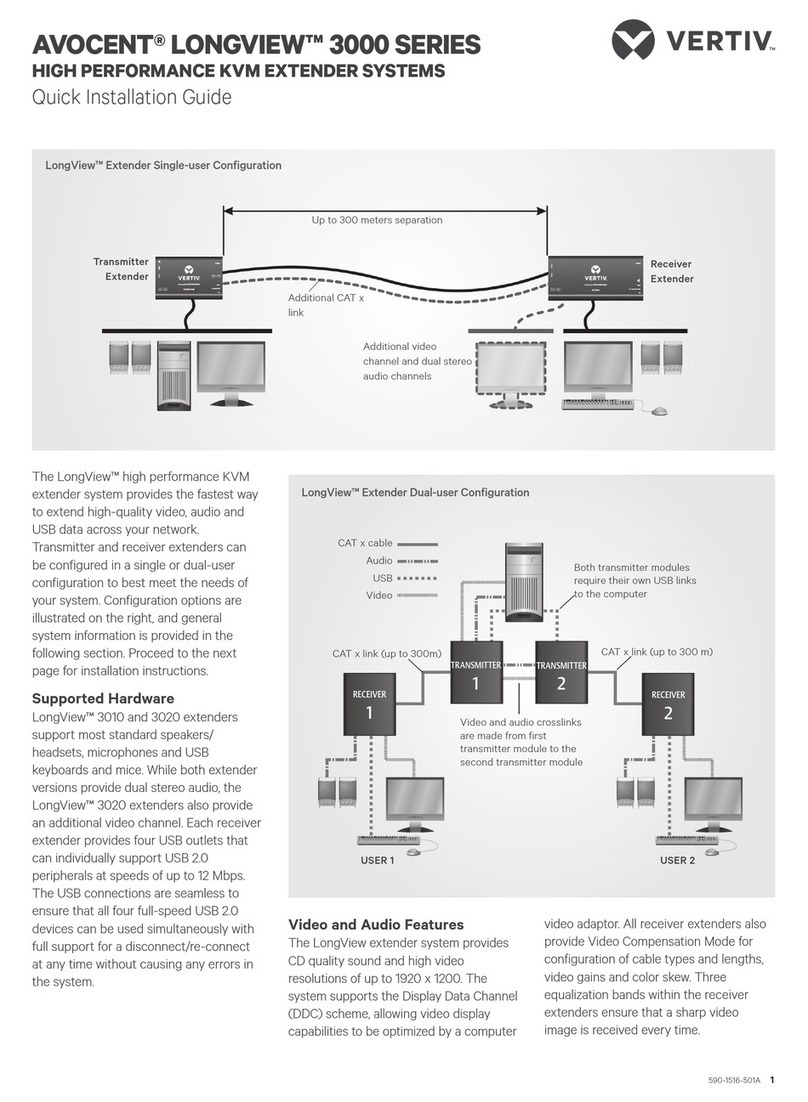
Avocent® LongView™ 5500/5520
Installer/User Guide
High Performance KVM Extender System

Vertiv™ | Avocent® LongView™ 5500/5520 High Performance KVM Extender System Installer/User Guide
Technical Support Site
If you encounter any installation or operational issues with your product, check the pertinent section of this
manual to see if the issue can be resolved by following outlined procedures.
Visit https://www.vertiv.com/en-us/support/ for additional assistance.
The information contained in this document is subject to change without notice
and may not be suitable for all applications. While every precaution has been
taken to ensure the accuracy and completeness of this document, Vertiv
assumes no responsibility and disclaims all liability for damages resulting from
use of this information or for any errors or omissions. Refer to other local
practices or building codes as applicable for the correct methods, tools, and
materials to be used in performing procedures not specifically described in this
document.
The products covered by this instruction manual are manufactured and/or sold
by Vertiv. This document is the property of Vertiv and contains confidential and
proprietary information owned by Vertiv. Any copying, use or disclosure of it
without the written permission of Vertiv is strictly prohibited.
Names of companies and products are trademarks or registered trademarks of
the respective companies. Any questions regarding usage of trademark names
should be directed to the original manufacturer.
Vertiv™ Avocent® LongView™ 5500/5520 High Performance KVM Extender System Installer/User Guide

TABLE OF CONTENTS
1 Product Overview 1
1.1 Features and Benefits 1
1.1.1 Video support 1
1.1.2 EDID management 1
1.1.3 USB support 2
1.1.4 Audio support 2
1.1.5 Serial support 2
1.2 Unit Overview 2
1.2.1 Operating modes 4
2 Configuration 7
2.1 Accessing the Dashboard 7
2.1.1 Dual-head mode (LongView 5520 models only) 7
2.2 Resetting a transmitter or receiver 8
2.3 Upgrading Firmware 8
3 Operation 9
3.1 Status Indicators 9
3.2 CATx Indicators 9
Appendices 11
Appendix A: Technical Specifications 11
Appendix B: Remote Port Pin-out 13
iii
Vertiv™ Avocent® LongView™ 5500/5520 High Performance KVM Extender System Installer/User Guide

iv
This page intentionally left blank
Vertiv™ Avocent® LongView™ 5500/5520 High Performance KVM Extender System Installer/User Guide

1 Product Overview
The Avocent® LongView™ 5500/5520high performance KVMextender system is a DisplayPort KVM extender that enables
you to locate your critical computing hardware in a secure and temperature controlled environment away from the user
workstation while maintaining the same user desktop experience. Using either one or two CATx cable links you can achieve
separation distances of up to 150 meters/492 feet between the transmitters and receivers. At such distances the units can
transfer high resolution DisplayPort video, USB 2.0 (low/full and hi-speed), digital and analog audio plus RS-232 serial.
1.1 Features and Benefits
1.1.1 Video support
The LongView 5000 extender system provides the highest possible video bandwidth between the transmitters and receivers.
To allow for the differing grades of CATx links, the extender system periodically checks the quality of the link and can
accurately determine which of the two video transfer modes can be supported. In low rate mode, the transmitter and receiver
extender units may be placed up to 492 feet (150 m) apart.
The following table displays the video bandwidth capabillities.
Item Fiber CATx
LV5500 Single head at 4Kmaximum Single head at 4Kmaximum
LV5520 Dual head at 4K maximum Single had at 4Kmaximum
Dual head at WQXGA maximum
Distances Up to 4 km Up to 100 m
Table 1.1 Video Bandwidth Capabilities
1.1.2 EDID management
The extender system intelligently manages the EDID (Extended Display Identification Data) information that each video
display provides before reporting to the host computer.
The LongView 5000 extender system supports, but is not limited to, the following video resolutions. All resolutions are
displayed at 60 fps.
•1920 x 1080 (HD)
•1920 x 1200 (WUXGA)
•2048 x 1080 (2K)
•2048 x 2160
•2560 x 1080
•2560 x 1440 (WQHD)
•2560 x 1600 (2.5K)
•2560 x 1600 (WQXGA)
•2560 x 2048 (QSXGA)
•3840 x 2160 (UHD)
•4096 x 2160 (4K)
1 Product Overview 1
Vertiv™ Avocent® LongView™ 5500/5520 High Performance KVM Extender System Installer/User Guide
1.1.3 USB support
A wide range of USB devices are supported on the receiver via the four ports on the front of the unit.
The LV5500 extender has four low/full speed (version 2.0) USB for keyboards and mice and other HID devices. The LV5520
extender has three low/full speed (version 2.0) USB for keyboards and mice and other HID devices and one hi-speed (version
2.0) transparent USB with transfer rates up to 80 Mbits/sec and supports mass storage and isochronous devices.
1.1.4 Audio support
The LongView 5000 extender system can transfer analog and digital audio signals across the CATx cable link. Standard
analog audio is supported through 3.5 mm jacks on the transmitters and receivers. Additionally, the line-in jack on the
transmitter and the line-out jack on the receiver are dual purpose. They can accept 3.5 mm analog jacks.
1.1.5 Serial support
The transmitters and receivers each have serial options ports which are used for firmware upgrades. The ports can also be
used for transferring high speed serial data across the CATx link.
1.2 Unit Overview
The following figures show the connectors on the transmitters and receivers.
1 Product Overview
2
Vertiv™ Avocent® LongView™ 5500/5520 High Performance KVM Extender System Installer/User Guide
Figure 1.1 LongView™ 5520Transmitter
Number Description Number Description
1 Recessed reset button 7 USB port for keyboard and mouse
2 CATx port for alternative link 8 Secondary DisplayPort video input
3 Front panel indicators 9 Primary DisplayPort video input
4 SFPport for fiber optic link 10 Audio line-out
5 Remote port for RS232 serial devices 11 Audio line-in
6 USB port 12 Power input
Table 1.2 Transmitter Descriptions
1 Product Overview 3
Vertiv™ Avocent® LongView™ 5500/5520 High Performance KVM Extender System Installer/User Guide

Figure 1.2 LongView™ 5520 Receiver
Number Description Number Description
1 Recessed reset button 8 USBports for keyboard and mouse
2 USB port for HIDdevices 9 Speaker port
3 USB port for transparent USB 10 Secondary DisplayPort video output
4 Front panel indicators 11 Primary DisplayPort video output
5 Microphone input 12 CATx port for alternative link
6 Headphone output 13 SFPport for fiber optic link
7 Remote port for RS232 serial devices 14 Power input
Table 1.3 Receiver Descriptions
1.2.1 Operating modes
The LongView 5000 extender system maximize the data that is transferred between them. The achievable throughput
depends upon the length and quality of the cable links that join the units.
Video signals are most sensitive to link quality and for this reason the extenders have two modes of operation: low rate mode
and high rate mode. The extenders periodically check the link quality and determine which video transfer mode can be
successfully used. The difference between the two modes is considerable as high rate mode can deliver over twice the video
bandwidth. You can also choose which mode to use by using the Hotkey functions. For more information, see Using hotkeys.
When the link mode changes, on-screen icons are displayed, while the indicators on the front panels of both units show which
mode is currently being used. If a rate change occurs, the entire data link is reset causing a momentary loss of the video, audio
and USB services.
1 Product Overview
4
Vertiv™ Avocent® LongView™ 5500/5520 High Performance KVM Extender System Installer/User Guide

Transmission distances using fiber
Depending on the type of fiber you use, you can dramatically increase the operation distance. For example, with multi-mode
fiber and an accompanying SFP module, you can achieve distances up to 400 meters. By comparison, with single-mode fiber,
the maximum distance is 4 km.
Distance Fiber Type Fiber Color Code HMX Module
70 m OM1 Orange HMX-MM-10G-SFP
150 m OM2 Orange HMX-MM-10G-SFP
380 m OM3 Aqua HMX-MM-10G-SFP
400 m OM4 Aqua HMX-MM-10G-SFP
4 km
OS1
Yellow HMX-SM-10G-SFP
OS2
Table 1.4 Transmission Distances
1 Product Overview 5
Vertiv™ Avocent® LongView™ 5500/5520 High Performance KVM Extender System Installer/User Guide

1 Product Overview
6
This page intentionally left blank
Vertiv™ Avocent® LongView™ 5500/5520 High Performance KVM Extender System Installer/User Guide

2 Configuration
2.1 Accessing the Dashboard
The LongView 5000 extender system typically configures itself automatically, collecting EDID information from attached
monitors and passing the details to the host computer. Unless an issue is encountered, the extender system works together
as soon as they are connected. The front panel indicators provide the primary source of status information. There is also a
dashboard on-screen display (OSD), which provides other details on the primary display.
Figure 2.1 On Screen Dashboard
To access or exit the dashboard:
1. Press and release the Ctrl key three times in quick succession. The three keyboard indicators flash once per
second.
2. Press the numeric key 1located above the main section of the keyboard.
NOTE: The 1 on the numeric keypad will not work.
When the dashboard is enabled, repeat the steps above to exit it.
2.1.1 Dual-head mode (LongView 5520 models only)
When the CATx link is used to connect the transmitter and receiver modules, the available bandwidth is reduced. On
LongView 5520 models, if dual high-resolution video displays are used, you can determine how the available bandwidth is
shared between them. Two modes are available:
•Balanced mode - Shares the available video bandwidth equally between the two video displays, regardless of the
EDIDs being reported. For example, 1920 x 1200 each on video displays that would ordinarily request a native
mode of 2560 x 1600.
•Priority mode - The primary video port takes priority, allowing it to display resolutions up to 4K, as reported by its
EDID. The remaining bandwidth is assigned to the second video head.
Figure 2.2 Balanced Mode Example
Figure 2.3 Priority Mode Example
2 Configuration 7
Vertiv™ Avocent® LongView™ 5500/5520 High Performance KVM Extender System Installer/User Guide

To choose the dual head mode:
1. Press and release the Ctrl key three times in quick succession. The three keyboard indicators flash once per
second.
2. Above the main section of the keyboard press 6for Balanced mode.
-or-
Press 7for Priority mode.
The dashboard displays either PRIfor Priority mode or BAL or Balanced mode next to the link speed.
NOTE: If you don't press a key within five seconds, or if you press a key other than 1, 6 or 7, the keyboard reverts to
normal operation.
2.2 Resetting a transmitter or receiver
On the left side of the front panel of each transmitter or receiver is a small reset hole used for special functions.
To reset a transmitter or receiver:
Using a thin tool such as a straightened paper clip, press and release the button concealed in the reset hole. The power
indicator displays red. After a few seconds, the power indicator changes from red to green to indicate the reset is complete.
2.3 Upgrading Firmware
Firmware upgrades can be found from the LongView 5000 extender system product page at www.vertiv.com.
To upgrade the firmware:
1. Download the appropriate firmware from the product page.
2. Copy the firmware file to an empty FAT-32 formatted USBmemory stick.
3. Ensure both the transmitter and receiver are linked and powered on. Also ensure that no USBdrives are inserted
in any of the receiver USBports.
4. Using a thin tool, such as a straightened paper clip, press and hold the reset button on the receiver until the
STSindicator flashes red/blue. The receiver is now in upgrade mode.
5. Wait for the STS indicator link to turn green, indicating the link has been established.
6. Insert the USB memory stick with the firmware file into the left USBport on the front panel of the receiver. Each
unit's STS indicators flash red/green to indicate the upgrade is in process. When the upgrade is complete, each
until will automatically reboot and run the new firmware.
NOTE: If the upgrade is not successful, the STSindicator illuminates red. If necessary, reboot the transmitter and
receiver to run the previous firmware.
2 Configuration
8
Vertiv™ Avocent® LongView™ 5500/5520 High Performance KVM Extender System Installer/User Guide

3 Operation
The LongView 5000 extender system is designed to be transparent in operation. All peripherals should respond as they
would when connected to your host computer.
3.1 Status Indicators
The transmitter and receiver contain various indicators to provide you with status information. Each has four multi-color
indicators on their front panels.
Indicator Description
PWR
Solid Red:Initial boot
Green:Ready for use
Flashing Red:An issue has been encountered. Power cycle to see if the issue persists
STS
Displays the link type
Alternating Red/Blue:Upgrade mode
Alternating Red/Green:Upgrade in progress
Solid Blue:Fiber 10Glink in use
Solid Green:CATx 5Glink in use
Solid Amber:Warning. See the dashboard for details
Solid Red:Error. See the dashboard for details
VID
Displays the status of the video connection
Off:No displays connected
Solid Red:No video on connected displays
Solid Amber:Video only on one connected display
Solid Green:Video on both connected displays
LNK
Displays the link status between the transmitter and receiver
Off:No link
Red:0-25 percent quality
Amber:25-50 percent quality
Yellow:50-75 percent quality
Green:75-100 percent quality
Table 3.1 Status Indicators Descriptions
3.2 CATx Indicators
The indicators on the CATx port connector of each transmitter and receiver provides information when a CATx link is in use.
Indicator Descripion
LINK Illuminates green when there is a CATx link between the transmitter and receiver
SPEED
Displays whether the speed is sufficient
Solid Amber:Speed is below the necessary 5 GB/sec. Check the CATx cable link for issues.
Solid Green:Link speed is good
Table 3.2 CATx Indicator Descriptions
3 Operation 9
Vertiv™ Avocent® LongView™ 5500/5520 High Performance KVM Extender System Installer/User Guide

3 Operation
10
This page intentionally left blank
Vertiv™ Avocent® LongView™ 5500/5520 High Performance KVM Extender System Installer/User Guide

Appendices
Appendix A: Technical Specifications
Category LongView 5500 LongView 5520
Environmental
Nominal Operating Power (W) 10W 10W
Peak Power (W) 12W 12W
External Power 12V DC, 1.5A 12V DC, 1.5A
Max operating Altitude (m) 2000 m (6500 ft) 2000 m (6500 ft)
Operating Temp range 0 to 40°C (32 to 104°F) 0 to 40°C (32 to 104°F)
Operating Humidity range (%RH) 0-80% 0-80%
Storage Temp range (°C) -10 to 50°C (14 to 122°F) - 10 to 50°C (14 to 122°F)
Storage Humidity range (%RH) 0 to 80% 0 to 80%
Max Thermal Dissipation (BTU) 41.94 41.94
MTBF (Tx / Rx) 530k / 520k hours 510k / 490k hours
MTBF (Pair) 260k hours 250k hours
Local Unit - Transmitter (Tx)
Tri-color status indicators 4 4
Video DisplayPort in and local pass-through out 2 x DisplayPort in
USB2.0 Type B 2 2
Audio Line in and out analog Line in and out analog
RJ12 serial port 1 1
RJ45 and SFP+ ports 1 1
Remote unit – Receiver (Rx)
Tri-color status indicators 4 4
Video 2 x DisplayPort out (second port is a duplicate) 2 x DisplayPort out
USB 2.0 Type A 4 3 full-speed and 1 high-speed (transparent USB)
Audio Mic in, headset and speaker out Mic in, headset and speaker out
RJ12 serial port 1 1
RJ45 and SFP+ ports 1 1
Physical Design
Construction Robust metal Robust metal
Transmitter and receiver dimensions 186mm/7.32” (w), 39mm/1.54” (h), 148mm/5.83” (d) 186mm/7.32” (w), 39mm/1.54” (h), 148mm/5.83” (d)
Transmitter weight 1.29kg / 2.84lbs 1.29kg / 2.84lbs
Appendices 11
Vertiv™ Avocent® LongView™ 5500/5520 High Performance KVM Extender System Installer/User Guide

Category LongView 5500 LongView 5520
Receiver weight 1.24kg / 2.73lbs 1.24kg / 2.73lbs
Power supply 100 to 240VAC, 47 to 63Hz 100 to 240VAC, 47 to 63Hz
12VDC 18W output from power supply unit. 12VDC 18W output from power supply unit.
Appendices
12
Vertiv™ Avocent® LongView™ 5500/5520 High Performance KVM Extender System Installer/User Guide
Appendix B: Remote Port Pin-out
The REMOTE port uses a 6p6c socket. The pin-out is listed below.
NOTE: Pins 2 and 3 are inactive. However, they are still connected internally. No links should be made to these pins.
Pin Signal
1 Sense/5V
2 Not used (do not use)
3 Not used (do not use)
4 GND
5 RX
6 TX
Table A.1 Remote Port Pin-out
NOTE: The transmitter detects the presence of an incoming power signal to determine whether 5V should be supplied
at the receiver.
Appendices 13
Vertiv™ Avocent® LongView™ 5500/5520 High Performance KVM Extender System Installer/User Guide

Vertiv™ Avocent® LongView™ 5500/5520 High Performance KVM Extender System Installer/User Guide
Vertiv.com | Vertiv Headquarters, 1050 Dearborn Drive, Columbus, OH, 43085, USA
© 2021 Vertiv Group Corp. All rights reserved. Vertiv™ and the Vertiv logo are trademarks or registered trademarks of Vertiv Group Corp. All other
names and logos referred to are trade names, trademarks or registered trademarks of their respective owners. While every precaution has been
taken to ensure accuracy and completeness here, Vertiv Group Corp. assumes no responsibility, and disclaims all liability, for damages resulting
from use of this information or for any errors or omissions. Specifications, rebates and other promotional offers are subject to change at Vertiv’s
sole discretion upon notice
590-2360-501A
This manual suits for next models
1
Table of contents
Other Vertiv Extender manuals

Vertiv
Vertiv AVOCENT LONGVIEW 3010 User manual

Vertiv
Vertiv AVOCENT LONGVIEW 4000 SERIES User manual

Vertiv
Vertiv HMX3080T User manual

Vertiv
Vertiv AVOCENT HMX8000 User manual

Vertiv
Vertiv Avocent LV 5000 Series User manual

Vertiv
Vertiv AVOCENT HMX8000 User manual

Vertiv
Vertiv AVOCENT LONGVIEW 5000 SERIES User manual

Vertiv
Vertiv Avocent LongView 5020P Installation and maintenance instructions

Vertiv
Vertiv HMX3080T User manual

Vertiv
Vertiv Avocent HMX Installation and maintenance instructions