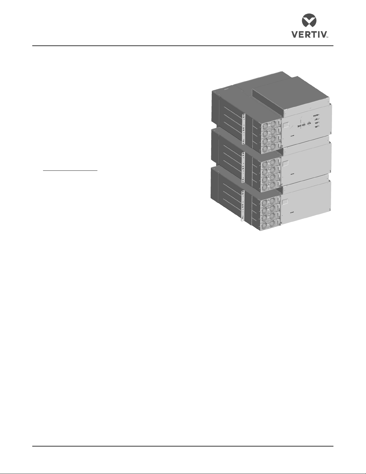
Vertiv™NetSure™DCS48375 Converter System
System Application Guide
Spec. No: 584622100, 584622200, SAG584622100, SAG584622200,
584622300, 584622400 Proprietary and Confidential © 2023 Vertiv Group Corp. SAG584622300, SAG584622400
Model No: DCS48375 Page 2 Revision J, May 9, 2023
TABLE OF CONTENTS
SYSTEM OVERVIEW............................................................................................................................................................................................................. 1
MAIN COMPONENTS ILLUSTRATIONS..........................................................................................................................................................................3
584622100 (19” Main Shelf), 584622300 (23” Main Shelf), 584622200 (19” Expansion Shelf), 584622400 (23”
Expansion Shelf) .............................................................................................................................................................................................................3
ORDERING INFORMATION.................................................................................................................................................................................................4
584622100 Main Shelf and 584622200 Expansion Shelves – 19” Version ......................................................................................................4
584622300 Main Shelf and 584622400 Expansion Shelves – 23” Version.....................................................................................................4
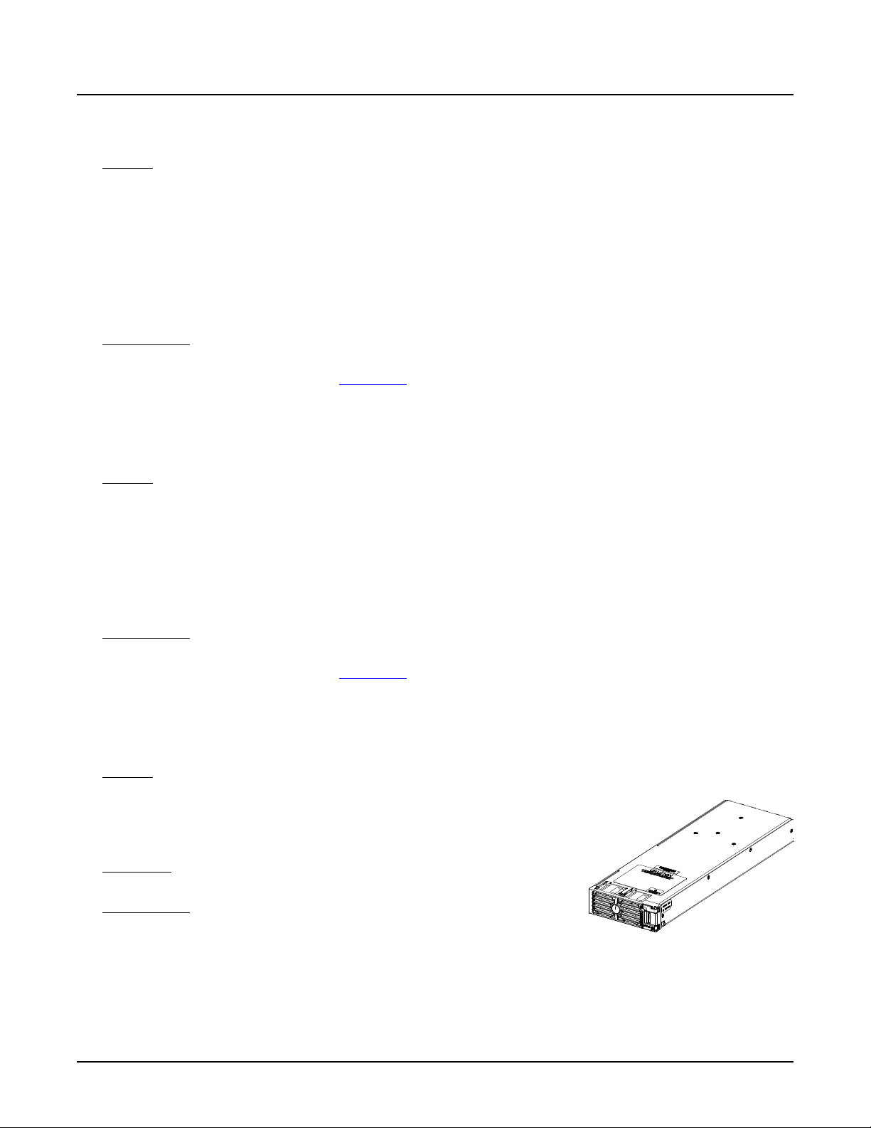
DC-DC Converter Module (P/N 1C24481500).........................................................................................................................................................4
Distribution Devices.......................................................................................................................................................................................................5
Bullet Nose Circuit Breakers and Bullet Nose Fuseholders e/w TPS/TLS Fuses.....................................................................................................5
Optional Bullet Nose 6-Position GMT Distribution Fuse Block (P/N 545333)............................................................................................................9
Bullet Nose Bypass Busbar (P/N 535015) ........................................................................................................................................................................................10
Replacement Alarm, Reference, and Control Fuses ..................................................................................................................................................................10
Special Application Crimp Lugs, Busbar Adapter Kits, and Hardware Kits ..................................................................................................10
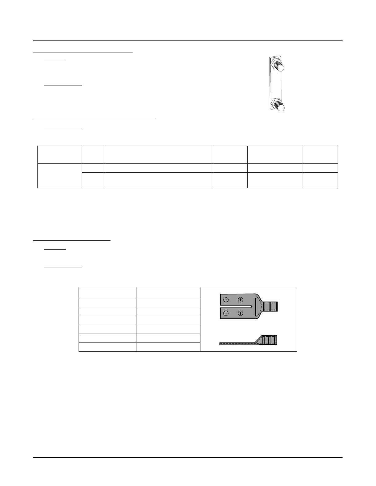
Special Application Crimp Lugs .............................................................................................................................................................................................................10
Busbar Adapter and Hardware Kits ......................................................................................................................................................................................................11
Wiring Notes ..................................................................................................................................................................................................................13
Recommended Frame Ground Wire Size and Lug Selection ...............................................................................................................................................13
Recommended DC Inputs Wire Sizes and Lugs Selection ....................................................................................................................................................13
Recommended Load Distribution Wire Sizes and Lugs Selection ...................................................................................................................................15
Recommended External Alarm, Reference, Monitoring, and Control Wire Sizes....................................................................................................17
Wiring Illustrations .......................................................................................................................................................................................................18
DC Inputs and Frame Ground ..................................................................................................................................................................................................................18
Load Distribution (TPS/TLS Fuses and Bullet Nose Circuit Breakers).........................................................................................................................19
Load Distribution (Optional Bullet Nose 6-Position GMT Fuse Block) ........................................................................................................................20
External Alarm, Reference, Monitoring, and Control.................................................................................................................................................................21
Shelf Interconnections ................................................................................................................................................................................................................................22
SPECIFICATIONS................................................................................................................................................................................................................ 24
1.1 System Output Ratings........................................................................................................................................................................................24
1.2System Input Ratings ...........................................................................................................................................................................................24
1.3 System Environmental Ratings.......................................................................................................................................................................... 24
1.4 System Compliance Information ....................................................................................................................................................................... 25
1.5 System Standard Features.................................................................................................................................................................................. 25
MECHANICAL SPECIFICATIONS................................................................................................................................................................................... 26
Overall Dimensions – 584622100 Main Shelf ....................................................................................................................................................... 26
Overall Dimensions – 584622200 Expansion Shelf ............................................................................................................................................ 27
Overall Dimensions – 584622300 Main Shelf ...................................................................................................................................................... 28
Overall Dimensions – 584622400 Expansion Shelf............................................................................................................................................ 29
RELATED DOCUMENTATION ........................................................................................................................................................................................30