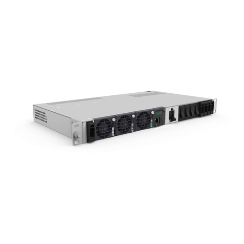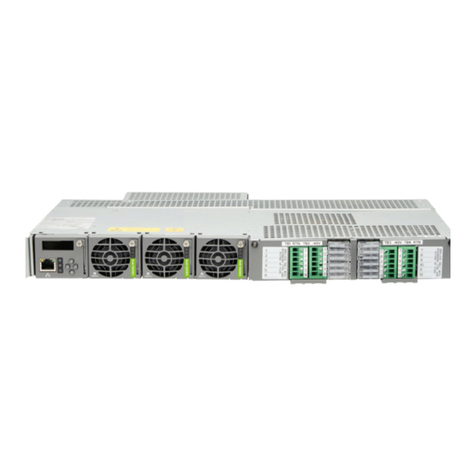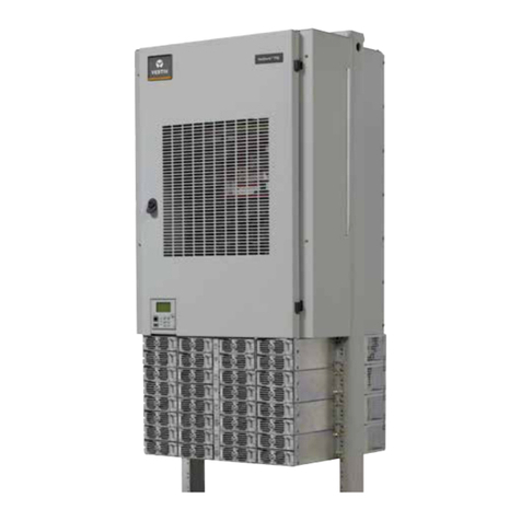
Vertiv™NetSure™802 and Vertiv™NetSure™8200 -48 VDC Power System
System Application Guide
Spec. No: 582140000 SAG582140000
Model Nos: 802NLDB, 802NLEB, 802NL-B, Proprietary and Confidential © 2022 Vertiv Group Corp. Revision BH, September 28, 2022
8200NLDB, 8200NLEB and 8200NL-BPage 7
Distribution Device and Load Lug Locations – Distribution Only Bays ........................................................................................................ 38
Distribution Devices.....................................................................................................................................................................................................41
218 Circuit Breaker Assemblies ..............................................................................................................................................................................................................41
TPL Fuses and Fuseholder Assemblies .................................................................................................................................................................45
Bullet Nose-Type Circuit Breakers and Bullet Nose-Type Circuit Breaker/Fuseholder Mounting Assembly –
Power/Distribution Bays ............................................................................................................................................................................................................................48
TLS/TPS Fuses, Bullet Nose-Type Fuseholders, and Bullet Nose-Type Circuit Breaker/Fuseholder Mounting
Assembly – Power/Distribution Bays .................................................................................................................................................................................................51
Bullet Nose-Type Circuit Breakers and Bullet Nose-Type Fuseholders e/w TLS/TPS Fuses – Distribution Only
Bays .........................................................................................................................................................................................................................................................................54
Optional Bullet Nose-Type 10-Position GMT Fuse Module for List C...........................................................................................................................56
Replacement Alarm, Reference, and Control Fuses (List 1, 2, 3, 4, 5, 11, 12, 13, 14, 15, 16, 17, 18, 22)........................................................ 57
Fuseblock Located in Bay’s Left Center ..........................................................................................................................................................................................57
Replacement Alarm, Reference, and Control Fuses (List 101, 102, 103, 104, 105, 111, 112, 113, 114, 115, 116, 117, 118, 122) .................... 58
Located in Bay’s Center Section...........................................................................................................................................................................................................58
Input and Alarm Fuse on Optional Bullet Nose-Type 10-Position GMT Fuse Module, P/N 509128 ..........................................................59
Optional Power/Distribution Bay Internal Ground Busbar Kits .......................................................................................................................60
Optional Internal Ground Busbar Kit (P/N 554862) ................................................................................................................................................................ 60
Optional Internal Ground Busbar Kit (P/N 555214)....................................................................................................................................................................61
Power/Distribution and Power Only Bays External Busbars............................................................................................................................ 62
Optional External Top-Mount Horizontal Battery Input Busbar Assembly...............................................................................................................62
Optional Busbar Shield Kit........................................................................................................................................................................................................................62
Optional External Top-Mount Ground (Load Return) Busbar Assemblies................................................................................................................63
Optional Load Return Lug Extension Busbar Assembly........................................................................................................................................................64
Optional External Top-Mount Vertical Battery Input Busbar Assembly.....................................................................................................................69
Optional Battery Charge Temperature Compensation Probe for Digital Compensation (List 1, 2, 3, 4, 5 Only) ................................ 72
Optional Temperature Probes (List 101, 102, 103, 104, 105 Only).................................................................................................................... 73
Optional SM-Temp Temperature Concentrator, P/N 547490 ......................................................................................................................... 73
Optional SM-IO2, P/N 02440103 ............................................................................................................................................................................. 74
Optional SM-DU+, P/N 10010507............................................................................................................................................................................ 75
Replacement/Additional Network Cable (List 111, 112, 113, 114, 115, 116, 117, 118, 122 Only)........................................................................ 76
Replacement/Additional Network Cable (List 11, 12, 13, 14, 15, 16, 17, 18, 22 Only) ...................................................................................... 76
Replacement/Additional LMS Network Cable (List 1, 2, 3, 4, 5, 11, 12, 13, 14, 15, 16, 17, 18, 22 Only) ........................................................ 76
Primary Bay NCU Retrofit Kit, P/N 565406 ...........................................................................................................................................................77
Secondary Bay NCU Retrofit Kit, P/N 565408......................................................................................................................................................77
Distribution Only Bay NCU Retrofit Kit, P/N 566156...........................................................................................................................................77
Distribution Only Bay NCU Retrofit Kit, P/N 566157 ...........................................................................................................................................77
User Replaceable Components................................................................................................................................................................................80
Models 802NLDB, 802NLEB and 802NL-B...........................................................................................................................................................................................80
Models 8200NLDB, 8200NLEB and 8200NL-B..................................................................................................................................................................................80
Wiring Components......................................................................................................................................................................................................81
Power/Distribution and Power Only Bays Frame Grounding Wire Sizes and Lugs...............................................................................................81
Distribution Only Bay Frame Grounding Wire Sizes and Lugs Selection....................................................................................................................82
Power/Distribution Bay and Distribution Only Bay Load Distribution Wire Sizes and Lugs..........................................................................83
Power/Distribution Bay Battery Cable Sizes and Lugs ..........................................................................................................................................................87
Power Only Bay DC Output Cable Sizes and Lugs....................................................................................................................................................................89
Distribution Only Bay DC Input Cable Sizes and Lugs Selection......................................................................................................................................91
Power/Distribution Bay AC Input, Ten (10) AC Feeds Wire Sizes, Branch Circuit Protection, and Lugs...............................................93
Power/Distribution Bay AC Input, Two (2) AC Feeds Wire Sizes, Branch Circuit Protection, and Lugs................................................95
Power/Distribution Bay AC Input, One (1) AC Feed Wire Sizes, Branch Circuit Protection, and Lugs....................................................97
Power Only Bay AC Input, Five (5) AC Feeds Wire Sizes, Branch Circuit Protection, and Lugs..................................................................99
Power Only Bay AC Input, Two (2) AC Feeds Wire Sizes, Branch Circuit Protection, and Lugs ................................................................101
Power Only Bay AC Input, Ten (10) AC Feeds Wire Sizes, Branch Circuit Protection, and Lugs..............................................................103
External Alarm, Reference, and Control Wire Sizes - Power/Distribution and Power Only Bays (List 1, 2, 3, 4, 5) ........................105
External Alarm, Reference, and Control Wire Sizes - Power/Distribution and Power Only Bays (List 101, 102, 103,
104, 105)..............................................................................................................................................................................................................................................................106
SPECIFICATIONS................................................................................................................................................................................................................111
1. System......................................................................................................................................................................................................................111
1.1 DC Operating Voltage........................................................................................................................................................................................................................111
