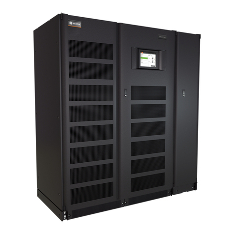
WARNING! Risk of heavy unit falling over. Improper handling can cause equipment damage,
injury or death. Because the weight distribution in the cabinet is uneven, use extreme care while
handling and transporting. Take extreme care when handling UPS cabinets to avoid equipment
damage or injury to personnel. Locate center of gravity symbols and determine unit weight
before handling each cabinet. Test lift and balance the cabinets before transporting. Maintain
minimum tilt from vertical at all times. The UPS module weighs up to 4667 lb. (2117 kg).
2.4.2 Clearances
The UPS has no ventilation grilles at either side or at the rear. Leave a distance of 24in. (610mm) between
the top of the UPS and any overhead obstacles for service and adequate circulation of air from the unit.
Clearance around the front of the equipment should be sufficient to enable free passage of personnel
with the doors fully opened, about 50in. (127cm). In the rare instance of module replacement, 50in.
(127cm) of clearance is required for the Service team to perform module replacement. 50in. (127cm)
allows adequate clearance for both the module and the heavy-duty lift used by Service team to remove
and replace the modules. If 50in. (127cm) is not available, then the Service team will instead replace
components and subassemblies in the modules as part of their repair process.
2.4.3 Raised-Floor Installations
If the equipment will be installed on a raised floor, mount the UPS on a pedestal suitably designed to
accept the equipment-point loading. Refer to the base view to design this pedestal.
2.4.4 Floor Anchors—Optional
For seismic-resistant installations, special floor anchors must be used for the UPS and matching battery
cabinets; see 5on page39.
2.4.5 Kick Plate Installation—Standard
Kick plates must be installed. If the unit will be installed in a position that does not permit access to rear of
the UPS, install the kick plates before the unit is placed in its final position.
2.4.6 Special Considerations for 1+N Parallel Systems
Consider the grounding configuration of your system before finalizing module placement See Configuring
Ground Connections on page 29.
The cabling impedance must be closely matched to ensure proper load-sharing. Mismatched impedance
may cause an overload on one module in a 1+N system, triggering a shutdown and loss of power to the
connected load. Mismatched cable impedance is amplified when a 1+N system is operating on bypass
because the power on the bypass path is not controlled. We recommend matching the impedance in the
bypass path of paralleled systems as closely as possible to ensure good bypass current sharing.
The 1+N UPS Bypass Current Sharing Inductor option can be used to minimize the effects of cable
impedance mismatch.
The impedance mismatch can also be minimized by controlling the wiring length of each unit. The design
and the layout of the UPS system and associated panels and cabling should be examined closely to
ensure that cable lengths and impedance are closely matched.
Vertiv | EXL S1™ Installer Guide
6
