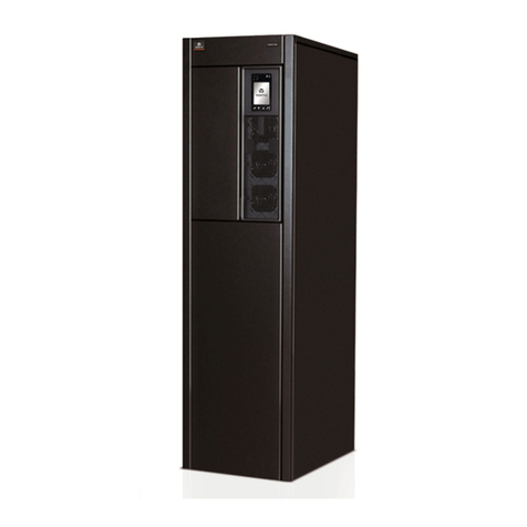
Liebert Trinergy™ Cube
Insta ation Manua - 10H52243IM60 - rev. 7 - 06/2020 Page 3
1. INTRODUCTION................................................................................................................. 5
1.1. Notes to the CE Dec aration of Conformity .................................................................................................. 5
1.2. Symbo s and pictograms ......................................................................................................................................... 5
1.3. Documentation structure........................................................................................................................................ 5
. MECHANICAL INSTALLATION ...................................................................................... 7
2.1. Transport .......................................................................................................................................................................... 7
2.2. De ivery and storage ................................................................................................................................................. 7
2.3. Pre-insta ation P anning......................................................................................................................................... 8
2.4. Pre iminary Checks .................................................................................................................................................... 8
2.5. Environmenta Considerations............................................................................................................................ 8
2.5.1 UPS room ............................................................................................................................................................. 8
2.5.2 Storing the UPS and Batteries for De ayed Insta ation....................................................... 10
2.6. Unpacking and un oading the cabinets from the pa et...................................................................... 11
2.7. Environmenta conditions..................................................................................................................................... 12
2.7.1 Insta ation a titude....................................................................................................................................... 12
2.8. Access to service area and coo ing system .............................................................................................. 13
2.9. Insta ation and footprint ...................................................................................................................................... 14
2.10. Physica appearance ............................................................................................................................................ 42
2.11. CORES assemb y procedure ........................................................................................................................... 47
2.11.1 I/O BOX 600-1200A with the CORES assemb y procedure (RIGHT SIDE CORES) 48
2.11.2 I/O BOX 2400A with the CORES assemb y procedure (RIGHT/LEFT SIDE CORE) 51
2.11.3 I/O BOX 3000A IN ROW assemb y procedure.......................................................................... 55
2.11.4 I/O BOX 4000-5000A BACK-TO-BACK assemb y procedure ....................................... 59
2.11.5 I/O BOX 4000-5000A IN ROW assemb y procedure............................................................ 65
3. ELECTRICAL CONNECTIONS I/O BOX TO CORES .................................................. 69
4. ELECTRICAL INSTALLATION ...................................................................................... 75
4.1. System and protective earthing ...................................................................................................................... 75
4.2. TN power distribution systems ....................................................................................................................... 75
4.3. TT power distribution systems........................................................................................................................ 78
4.4. IT power distribution systems ......................................................................................................................... 79
4.5. Externa protection devices in TN-C, TN-S, TT, IT systems......................................................... 80
4.5.1 Use of differentia protection devices............................................................................................ 80
4.5.2 Primary ine power input.......................................................................................................................... 81
4.5.3 Bypass ine power input ........................................................................................................................... 81
4.5.4 Battery input................................................................................................................................................... 81
4.5.5 Backfeed protection................................................................................................................................... 81
4.6. Customer power wiring: current and suggested cab e sizes......................................................... 83
4.6.1 UPS output ine............................................................................................................................................. 84
4.7. Externa power connections.............................................................................................................................. 85
4.7.1 Power connections (CORE and I/O BOX)...................................................................................... 86
4.8. Configuring Ground Connections ............................................................................................................... 104
4.9. Connecting the batteries .................................................................................................................................. 105
4.10. Connections between battery compartments and UPS............................................................... 107
4.11. Hand ing the batteries ....................................................................................................................................... 108
4.11.1 Recharging batteries .............................................................................................................................. 108
4.11.2 Rep acing batteries................................................................................................................................. 108
4.11.3 Connecting externa batteries ......................................................................................................... 108
5. CONNECTIVITY............................................................................................................. 109
5.1. UPS signa wiring: interconnecting the communication cab es................................................. 109
5.2. Customer signa wiring ........................................................................................................................................ 116
5.2.1 SUB-D connector for para e UPS: centra ized para e system cab e connection -
