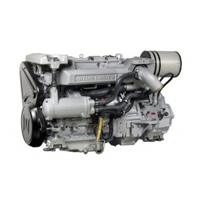
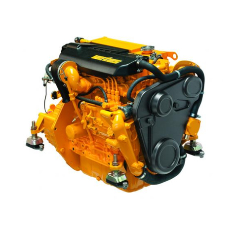
Vetus VF4.170E User manual

Installation manual
VF4 VF5 VF4.140E
VF4.170E
VF4.190E
VF5.220E
VF5.250E

vetus®Installation manual VF4 VF5
400202.01
Copyright © 2012 Vetus n.v. Schiedam Holland

400202.01 1
vetus®Installation manual VF4 VF5
1 Preface ..................................................................... 3
1.1 Engine ID Plates .......................................................... 3
1.2 Engine storage, before use .................................................. 4
1.3 First engine start .......................................................... 4
1.4 Long engine storage – Inactivity ............................................. 6
2 Technical data .............................................................. 8
2.1 Engine specifications ...................................................... 8
2.2 Engine cylinder numbering ................................................. 10
2.3 Engine coat paint RAL ..................................................... 10
2.4 Tightening torque ........................................................ 10
2.5 Operation / duty cycle ..................................................... 11
2.6 Engine bed ............................................................. 11
2.7 Overall dimensions ....................................................... 12
2.8 Raw water circuit ........................................................ 16
3 Safety Information ......................................................... 17
3.1 Safety rules ............................................................. 17
3.2 Engine lifting ............................................................ 19
4 Engine’s requirements ..................................................... 21
4.1 Engine Compartment ..................................................... 21
4.1.1 Engine Compartment Ventilation ...................................... 21
4.1.2 Intake air requirement .............................................. 22
4.1.3 Compartment temperature indications. ................................. 22
4.2 Fuel connection ......................................................... 23
4.2.1 Fuel Delivery System ............................................... 23
4.2.2 Fuel connections ................................................... 24
4.2.3 Shut off valve. ..................................................... 24
4.2.4 Diesel fuel Pre-filter and fuel additives. ................................. 24
4.3 Sea water circuit ......................................................... 25
4.3.1 Sea cock ........................................................ 25
4.3.2 Seawater pickup hose .............................................. 25
4.3.3 Seawater strainer .................................................. 25
4.3.4 Stern drives sea water pick up circuit. .................................. 26
4.3.5 Fittings .......................................................... 26
4.4 Exhaust system .......................................................... 26
4.4.1 Wet exhaust systems installation. ...................................... 26
4.4.2 Sea water intrusion through the intake sea-cock .......................... 28
4.4.3 Cranking the starter: draining the muffler ................................ 28
Contents

2 400202.01 vetus®Installation manual VF4 VF5
4.5 Exhaust system for stern drive version ....................................... 29
4.6 Propeller selection ........................................................ 30
4.7 Gearbox version: propeller shaft alignment .................................... 31
4.8 Engine bed mounting ..................................................... 32
5 Electric/electronic system .................................................. 33
5.1 Electrical system . . . . . . . . . . . . . . . . . . . . . . . . . . . . . . . . . . . . . . . . . . . . . . . . . . . . . . . . . 33
5.1.1 Battery connection ................................................. 33
5.1.2 Diagrams ......................................................... 33
5.1.3 Connecting the battery cable ......................................... 38
5.1.4 Battery cable size .................................................. 39
5.1.5 Battery specification ................................................ 40
5.1.6 Fuses and relays indications ......................................... 41
5.2 Elements that constitute the electronic control of the Vetus VF series engines ........ 42
5.2.1 Engine installation wirings ........................................... 43
5.2.2 Engine harness .................................................... 44
5.3 Electronic command system: ............................................... 46
5.3.1 Maximum specifications of the system .................................. 46
5.3.2 Command station – Pilot instruction .................................... 47
5.3.3 Friction adjustment ................................................. 47
5.3.4 Control keypad .................................................... 47
5.3.5 Taking over control ................................................. 49
5.3.6 Warming up the engine (Warm-up) .................................... 49
5.3.7 Synchro mode operation ............................................ 49
5.3.8 Mechanical installation .............................................. 50
5.3.9 Connection of push-pull cable ........................................ 51
5.3.10 Installation of power supply .......................................... 54
5.3.11 Power supply ..................................................... 54
5.3.12 Outgoing cables from the control box .................................. 55
5.3.13 Trim cable ........................................................ 56
5.3.14 Programming keypad ............................................... 58
5.3.15 Setting the parameters ............................................. 60
5.3.16 Mechanical setting of the stroke of the gearbox .......................... 61
5.3.17 Trim command .................................................... 62
5.3.18 Emergency lever ................................................... 62
5.3.19 Unexpected switching off of the engines ............................... 62
6 Optional .................................................................. 63
6.1 Fly bridge station installation ............................................... 63
6.2 Water Heater Installation .................................................. 64
7 Checks ................................................................... 67
7.1 Diagnosis ............................................................... 67
7.2 Check the engine oil level .................................................. 67
400202.01 3
vetus®Installation manual VF4 VF5
1 Preface
The reliability of the total propulsion unit is dependent on the quality of the installation.
Nearly all the problems are caused by faults or inaccuracies which occur during the installation. It is
most important therefore to follow during installation the recommendations mentioned in this manual.
1.1 Engine ID Plates
The ID labels are placed on the engine as shown in the pictures below:
The engine number is marked on the engine where indicated in the picture below:

4 400202.01 vetus®Installation manual VF4 VF5
1.2 Engine storage, before use
If the engine is stored for a prolonged period, check the possible conditions of conservation in relation to the
storage environment and the type of packaging.
The engine is supplied with a protection treatment which is valid for 6 months from delivery date.
1 Check for the coolant (coolant circuit). The engine supplied with a mixture to withstand storage temperature
of -15 °C (5 °F).
2 Attention: The raw water circuit could contain engine test bed water. Drain completely the raw water
circuit if the storage temperature is lower than 0°C (32°F).
3 Grease the turbocharger operating mechanism after this period.
4 Verify the packages integrity.
5 Humidity and salt corrosion could damages the engines during their storage.
1.3 First engine start
1 Read the owner’s manual.
2 Verify the fuel feed line for possible leaks. Take care to avoid restrictions in the fuel line pipes.
3 Verify and if required grease all the couplings, the turbocharger operating mechanism.
4 Check and verify the electrical connections. Important: Wrong connection of positive and negative could
provoke short circuit and damage the engine.
5 Check the battery condition and state of charge.
6 Check the raw water circuit, the connection and open the sea cock.
7 Check the belt and belt tensioner.
8 Check coolant level and oil levels of both engine and gearbox, verify if fuel is available in the tank. Fuel tank
must be clean!
9 Turn ON the red button on the ECU box and verify that the fuse LED’s light-up.
10 Verify the position of the control lever and make sure it is in Neutral position.
11 Verify the gearbox – stern drive oil level.

400202.01 5
vetus®Installation manual VF4 VF5
12 Make engine diagnosis. Important: Compile and send the installation form data request.
13 Verify the engine – propulsion alignment, grease the mechanical connections.
14 Start the engine, lets warm up the engine for few minutes at minimum RPM idle.
15 Verify for any leaks, verify the sea water pump, and verify the flush of water on exhaust system, verify that all
warning lights on the instrument panel are OFF and no alarm buzzer sounds and verify if oil pressure – water
temperature and charge current are OK *.
Important: If you hear a strange noise, or vibration of the engine is extreme or black smoke is
coming out of the exhaust stop the engine immediately and ask for assistance.
When the temperature of the engine stabilizes at a temperature higher than normal it might be neces-
sary to bleed the coolant circuit.
Bleeding the coolant circuit:
• Opentheexpansiontankcaptolettheairescape.
• IncreasetheRPMto2000anddecreasefewtimeswithoutengagingthegearbox.
• Addwatertothecoolantcircuitifnecessary.
• Closethecap.
• Verifytheenginecoolanttemperatureagain.
16 Take the command on the levers.
17 Never exceed the first time 3/4 of maximum rpm.
18 Verify all person are on board and engage the gear to test the gearbox – stern drive and carry bout the sea
trial.

6 400202.01 vetus®Installation manual VF4 VF5
1.4 Long engine storage – Inactivity
If the engine remains inactive for a period of time exceeding 6 months, you need to protect it from oxidation and
breakdowns in accordance with the following instructions:
1 Let the engine run for 15 minutes at 800 rpm; stop the engine and drain the oil.
2 Put oil (according to the specifications MIL-60B-type 2) into the oil sump until the oil sump reaches at least
‘Min’ on the oil dipstick.
3 After emptying the fuel filters, disconnect the pipes of the feeding of the injection system at the top of the
feeding pump, and connect it with the proper tank containing oil CFB (ISO 4113).
4 Let the engine run for 15 min. at 800 rpm; then, by using an oil gun, slowly atomize (nebulize) for about one
minute 60 grams of oil MIL-60B-type-2 into the intake manifold.
5 Disconnect the pipes of the feeding of the injection system from the tank containing the oil CFB and re-
connect it to the fuel tank.
6 Seal with tape, on both the engine and exhaust pipe, the access lights, aeration lights and breather pipe
lights.
7 Put a very visible paper on the engine where it is clearly stated that the engine is ‘WITHOUT OIL’.
8 Disconnect the batteries and put them in a dry place, always making sure that they are charged.
9 Drain the cooling water in case it does not have anti-freezing liquid or anti-corrosion liquid
10 If the engine is connected with the propulsion system verify for the oil level.
11 Clean the engine from salt and eventual rust. Paint rusted parts. Spray the engine with CRC 6-66 marine
lubricant spray to avoid corrosion.
After a period of inactivity, it is necessary to carry out a some maintenance work before starting the
engine again to ensure its efficiency conditions.
1 Check the battery charge level conditions. Assure that the battery voltage is over 12.5 V.
2 Make sure the electric contacts are intact. Assure the correct electrical connections.
3 Carry out the engine diagnosis.
4 Check the oil level-conditions, and if necessary, top- up or replace.
5 Verify and if necessary replace the oil filter.
6 Check the coolant level an mixture, and if necessary top – up.
7 Replace / Clean the fuel filter.
8 Clean the air filter.
9 Verify the belts status and tighteners.
10 Verify the integrity of the sea water pump impeller.

400202.01 7
vetus®Installation manual VF4 VF5
11 Check the integrity of electrolytic zincs.
12 Verify and if is necessary grease: starter pinion, turbocharger leverages mechanical propulsion couplings.
13 Start the engine and run at minimum speed for few minutes.
14 If no anomalies bring the engine to its operating temperature, 70 - 80 °C (158 - 176 °F). Verify that there is
no air in the coolant circuit – bleed the air from coolant circuit if necessary.
15 Turn off the engine and check again the engine oil level and coolant level.
16 Verify for tightening.

8 400202.01 vetus®Installation manual VF4 VF5
2 Technical data
2.1 Engine specifications
Model : VF4.140E VF4.170E VF4.190E VF5.220E VF5.250E
General
Make : Vetus C.M.D.
Number of cylinders :44455
Type : 4-stroke diesel, in-line, DOHC
Injection : Direct injection, common rail
Aspiration : Turbo-charged with variable geometry
Bore : 82 mm 82 mm 82 mm 82 mm 82 mm
Stroke : 90,4 mm 90,4 mm 90,4 mm 90,4 mm 90,4 mm
Total displacement :1910 cm3
(116 cu.inch)
1910 cm3
(116 cu.inch)
1910 cm3
(116 cu.inch)
2387 cm3
(146 cu.inch)
2387 cm3
(146 cu.inch)
Idling speed :800 rpm 800 rpm 800 rpm 750 rpm 750 rpm
Max. no. of revolutions at no
load
:4700 rpm 4700 rpm 4700 rpm 4700 rpm 4700 rpm
Max. no. of revolutions at
max. load
:4000 rpm 4000 rpm 4000 rpm 4200 rpm 4200 rpm
Direction of rotation counter clockwise, viewed from the flywheel side
Weight (with standard
gearbox) :320 kg
(705 lbs)
320 kg
(705 lbs)
320 kg
(705 lbs)
333 kg
(734 lbs)
333 kg
(734 lbs)
Engine installation
Max. installation angle :10 degrees backwards
Max. athwartships angle :20 degrees continuously, 30 degrees intermittend
Maximum Output
at the flywheel (ISO 3046-1) :103 kW
(140 hp)
125 kW
(170 hp)
140 kW
(190 hp)
162 kW
(220 hp)
184 kW
(250 hp)
at the prop shaft
(ISO 3046-1) :99.9 kW
(135.8 hp)
121.2 kW
(164.9 hp)
135.8 kW
(184.3 hp)
157.1 kW
(213.4 hp)
178.5 kW
(242.5hp)
at no. of revolutions of :4000 rpm 4000 rpm 4000 rpm 4000 rpm 4200 rpm
Torque, :
310 Nm
(31.6 kgm,
2441 ft.lb)
345 Nm
(35.1 kgm,
254 ft.lb)
370 Nm
(37.7 kgm,
273 ft.lb)
416 Nm
(42.4 kgm,
307 ft.lb)
450 Nm
(45.9 kgm,
332 ft.lb)
at no. of revolutions :2400 rpm 2200 rpm 2400 rpm 2500 rpm 2600 rpm
Fuel consumption :
215 g/kW.h
(158 g/hp.h)
(5.6 oz/hp.h)
237 g/kW.h
(174 g/hp.h)
(6.1 oz/hp.h)
231 g/kW.h
(170 g/hp.h)
(6.0 oz/hp.h)
236 g/kW.h
(173 g/hp.h)
(6.1 oz/hp.h)
260 g/kW.h
(191 g/hp.h)
(6.7 oz/hp.h)
at no. of revolutions :4000 rpm 4000 rpm 4000 rpm 4000 rpm 4000 rpm
Fuel System (Self-bleeding)
Fuel lift pump :Suction height max. 1,5 m (5 ft)
Fuel supply connection :8 mm (5/16") I.D.
Fuel return connection :8 mm (5/16") I.D.

400202.01 9
vetus®Installation manual VF4 VF5
Model : VF4.140E VF4.170E VF4.190E VF5.220E VF5.250E
Oil lubrication system
Oil capacity, max.
without oil filter :4 l (7 UK pt, 8.5 US pt) 4.5 l (7.9 UK pt, 9.5 US pt)
with oil filter :4.5 l (7.9 UK pt, 9.5 US pt) 5 l (8.8 UK pt, 10.6 US pt)
Cooling system
Capacity, 7.6 litres
(1 gal - 5.4 pt UK) (2 US gal)
8.5 litres
(1 gal - 7 pt UK) (2 gal - 2 pt
US)
Thermostat : opening at 65°C ± 1.5°C (149°F ±3°F), fully opened at 76°C (169°F)
Coolant pump,
Flow at max. engine rpm :90 l/min (19.8 UK gal/min, 23.8 US gal/min)
Raw water pump,
Flow at max. engine rpm :100 l/min (22 UK gal/min, 26.4 US gal/min)
Total head at max. flow :1.5 bar (21 psi)
Inlet connection for hose :32 mm (1 1/4") I.D.
Heater supply connection :32 mm (1 1/4") I.D.
Heater return connection :32 mm (1 1/4") I.D.
Exhaust system
Exhaust diameter :for gear box 90 mm
for stern drive 76 mm (3")
Exhaust back pressure :at specified output max. 300 mbar
Electrical System
Voltage : 12 Volt
Alternator : 14 Volt, 105 A 14 Volt, 140 A
Startmotor : 14 Volt, 2.3 kW
Capacity, starter battery :min. 70 Ah, max. 200 Ah
Protection : Fuse 'ATO' 10 Amp
Gearbox Gear ratio
Technodrive: type TM345 :1.54 : 1 — —
type TM345A :1.54 : 1 — —
type TM485A :2.09 / 2.40 / 2.51 : 1 2.09 / 2.40 / 2.51 : 1
ZF Hurth: type ZF25 :1.97 : 1 ————
type ZF25A :2.03 : 1 ————
type ZF45 :2.20 / 2.51 : 1 2.20 / 2.51 / 3.03 : 1
type ZF45A :1.26 / 1.51 / 2.03 / 2.43 : 1 1.26 / 1.51 / 2.03 / 2.43 : 1
type ZF63 IV :2.00 / 2.48 : 1 2.00 / 2.48 : 1

10 400202.01 vetus®Installation manual VF4 VF5
2.2 Engine cylinder numbering
2.3 Engine coat paint RAL
SIKKENS LV AUTCOAT 450 RAL 1007
2.4 Tightening torque
Tightening torque for vital connections, which should be tightened with a torque wrench are indicated in the
pictures.
The torque readings refer to lightly oiled or dry thread, screw heads and mating surfaces. For connections
where special torque denotations are not indicated, the general tightening torque is applicable according to the
table below. The torque readings are guide values, and connections do not need to be tightened with a torque
wrench.
The screws and nuts divided into different class. It is therefore important when a screw connection is dismantled
to return the screw to their original positions. The table refer to 8.8 class screws.
Size Tightening torque (Nm )
M5 6
M6 10
M8 25
M10 50
M12 80
M14 100
1234 12345

400202.01 11
vetus®Installation manual VF4 VF5
2.5 Operation / duty cycle
With respect to operation and duty cycle VF4 and VF5 diesel engines are rated for
PLEASURE CRAFT DUTY ONLY!
Maximum RPM:
Model Max. RPM (under load)
VF4 series 4000
VF5 series 4200
Wide open throttle operation is limited to short periods of time.
Important: Damage caused by improper application or failure to operate within the operational
capability or duty cycle, will not be covered by the Vetus Warranty.
2.6 Engine bed
The engine bed should have sufficient stiffness and strength: it must be bonded or connected over its total
length to the bottom of the boat and in addition must have sufficient transverse reinforcement either by its own
method of construction or alternatively by the use of straightening ribs.
An engine which is easily accessible will be inexpensive to work on is terms of both time and money, for example
the water pump situated on the rear side required a sufficient distance from bulkheads.
It is particularly important that both sides of the engine are easily accessible.
The engine inclination should never exceed 15° backwards.

12 400202.01 vetus®Installation manual VF4 VF5
2.7 Overall dimensions
700 (27 35/64”)
350 (13 49/64”) 350 (13 49/64”)
315 (12 3/8”) 305 (12”)
min. 82 (3 1/4”)
max. 110 (4 5/16”)
VF4.140E
TM345A
120 (4 3/4”) 515 (20 1/4”)
700 (27 9/16”)
960 (37 13/16”)
260 (10 1/4”)
190 (7 1/2”) 505 (19 7/8”)
695 (27 3/8”)
111 (4 3/8”)
192 (7 9/16”)
224 (8 13/16”)
8˚
VF4.140E
VF4.170E
VF4.190E
ZF45
700 (27 35/64”)
350 (13 49/64”) 350 (13 49/64”)
315 (12 3/8”) 305 (12”)
min. 82 (3 1/4”)
max. 110 (4 5/16”)
120 (4 3/4”) 515 (20 1/4”)
700 (27 9/16”)
1010 (39 3/4”)
310 (12 3/16”)
190 (7 1/2”) 505 (19 7/8”)
695 (27 3/8”)
150 (5 7/8”)
290 (11 7/16”)
260 (10 1/4”)
230 (9 1/16”)
VF4.170E, VF4.190E

400202.01 13
vetus®Installation manual VF4 VF5
700 (27 35/64”)
350 (13 49/64”) 350 (13 49/64”)
315 (12 3/8”) 305 (12”)
min. 82 (3 1/4”)
max. 110 (4 5/16”)
VF4.140E
TM345A
120 (4 3/4”) 515 (20 1/4”)
700 (27 9/16”)
960 (37 13/16”)
260 (10 1/4”)
190 (7 1/2”) 505 (19 7/8”)
695 (27 3/8”)
111 (4 3/8”)
192 (7 9/16”)
224 (8 13/16”)
8˚
1 : 10
VF4.170E
VF4.190E
ZF45
700 (27 35/64”)
350 (13 49/64”) 350 (13 49/64”)
315 (12 3/8”) 305 (12”)
min. 82 (3 1/4”)
max. 110 (4 5/16”)
120 (4 3/4”) 515 (20 1/4”)
700 (27 9/16”)
1010 (39 3/4”)
310 (12 3/16”)
190 (7 1/2”) 505 (19 7/8”)
695 (27 3/8”)
150 (5 7/8”)
290 (11 7/16”)
260 (10 1/4”)
230 (9 1/16”)
1 : 10

14 400202.01 vetus®Installation manual VF4 VF5
710 (27 61/64”)
350 (13 49/64”) 360 (14 11/64”)
305 (12”) 305 (12”)
VF5.220E
ZF45
VF5.250E
120 (4 3/4”) 600 (23 5/8”)
720 (28 3/8”)
1030 (40 9/16”)
230 (9 3/32”)
150 (5 15/16”)
290 (11 7/16”)
195 (7 43/64”) 505 (19 7/8”)
705 (27 3/4”)
min. 82 (3 1/4”)
max. 110 (4 5/16”)
VF5.220E, VF5.250E
710 (27 61/64”)
350 (13 49/64”) 360 (14 11/64”)
260 (10 1/4”)
559 (22”)
820 (32 9/32”)
1695 (66 47/64”)
776 (30 35/64”)
VF5.220E
VF5.250E
BRAVO ONE
195 (7 43/64”) 510 (20 5/64”)
705 (27 3/4”)
265 (10 7/16”)
94(3 11/16”)
min. 82 (3 1/4”)
max. 110 (4 5/16”)
VF5.220EB1, VF5.250EB1

400202.01 15
vetus®Installation manual VF4 VF5
710 (27 61/64”)
350 (13 49/64”) 360 (14 11/64”)
305 (12”) 305 (12”)
VF5.220E
ZF45
VF5.250E
120 (4 3/4”) 600 (23 5/8”)
720 (28 3/8”)
1030 (40 9/16”)
230 (9 3/32”)
150 (5 15/16”)
290 (11 7/16”)
195 (7 43/64”) 505 (19 7/8”)
705 (27 3/4”)
min. 82 (3 1/4”)
max. 110 (4 5/16”)
1 : 10
710 (27 61/64”)
350 (13 49/64”) 360 (14 11/64”)
260 (10 1/4”)
559 (22”)
820 (32 9/32”)
1695 (66 47/64”)
776 (30 35/64”)
VF5.220E
VF5.250E
BRAVO ONE
195 (7 43/64”) 510 (20 5/64”)
705 (27 3/4”)
265 (10 7/16”)
94(3 11/16”)
min. 82 (3 1/4”)
max. 110 (4 5/16”)
1 : 10

16 400202.01 vetus®Installation manual VF4 VF5
2.8 Raw water circuit
The engine heat exchange circuit is represented in the block diagram below:
The sequence is as follows:
1 the raw water cools the power steering oil or the gearbox oil and the fuel feed circuit;
2 then the air compressed air from the turbo is cooled (After cooler);
3 then the internal coolant circuit is cooled;
4 then the exhaust elbow is cooled
5 the the raw water is injected into the exhaust gasses and mixed with the exhaust gasses it goes overboard.
Sea water pump
Gearbox
Oil Cooler
Exhaust Gas
Sea water IN
Fuel
Cooler
Engine Coolant
Heat Exchanger
Charge Air
Heat Exchanger
Exhaust
Elbow To Exhaust
Transom Fitting

400202.01 17
vetus®Installation manual VF4 VF5
3 Safety Information
The operation manual contains technical data and maintenance instructions for the designated Vetus engines.
Read the instruction and information before starting service works.
WARNING - Hazards or unsafe practices which could result in severe personal injury or serious
product damages.
CAUTION - Hazards or unsafe practices which could result in minor personal injury or product
damages-malfunctions.
3.1 Safety rules
• Themanufacturercannotbeheldresponsibleforanydamageresultingfrommisuseoftheengine,fromthe
failure to follow the indications contained in this manual and for every tampering with or change made without
the manufacturer’ s authorization.
• Referonlytoatechnicianstaff,withprecisetechnicalskills,specificabilitiesandexperiences.
The lack of these requirements could provoke damages to people’s safety.
• Usetheengineonlyforthetaskauthorizedbythemanufacturer,donotmanipulateanythingtoobtaindiffer-
ent performances.
• Whenliftandduringthetransportofunpackedengineusemeansofappropriateloadcapacity.
• Whenliftpackedenginepayattentiononloadindicationprintedonbox!
• During the installation the installer had to follow the designer’s indications. Do not make changes to the
engine components for any reason.
• Ifappropriate,beforeusingtheengineforthefirsttimesimulateafewtrialmanoeuvrestoidentifythecontrols
and their main functions, especially those related to start -stop operations and emergency operations.
• Donotkeepusingtheengineifanomaliesaredetected.
• Incaseofanomaly,stopimmediatelytheengineorreducethespeedasmuchaspossible.Startagainonly
when normal condition are restored.
• Replaceonlyoriginalspareparts.Useoilsandgreasesrecommendedbymanufacturer.
• Stoptheengineandswitchofthepowerwiththemainswitch(switches)beforeworkingontheelectrical
system.
• Neverstarttheenginewithoutairfilter,turbocompressorrotorcouldprovokedamages.Dirtycoulddamage
the engine.
• Don’t smoke near the battery pack ! The battery release flammable gases. Wrong battery connection could
provoke sparks and explosion.
• Neverconfusetheplusandminusterminalwhenfittingsthebatteries.

18 400202.01 vetus®Installation manual VF4 VF5
• Usecorrectprotection(clothesetc.)duringmaintenanceoperations!
• Switchingthegearboxshouldbeconductedonlywhentheengineisatidlespeed.
• Alwaysclosetherawwaterinletvalvewhenyoudismountthecoolantsystem!
• Neverusestartersprayorsimilar.Topreventtheriskofexplosionintheairinletpipe.
• Avoid to opening the coolant filler cap when the engine is hot. Steam or hot coolant can spray out, and
built up pressure will be lost. Open the filler cap slowly and release the overpressure if the filler cap must be
opened.
• Hotoilcancauseburntinjuries.Avoidskincontactwithhotoil.Makesurethattheoilsystemisnotpressu-
rized before working on it. Never start the engine with the oil filter cap removed!
• During maintenance operation make sure that the engine room is well ventilated.
• Donotthrowawayanypollutingmaterial.Followthelocalrulesoflegislation.
• Ifyouwashtheenginewithhighpressurewash,observethefollowing:
- never point the jet of water at seals, rubber hoses or electrical components.
- never use high pressure function when washing the engine.
• Usethecorrectfuel,seethefuelindications.
• Keep the equipment as much efficient as possible and carry out the scheduled maintenance operations
established with the manufacturer.
Important
This installation manual has been published by VETUS to aid the boat manufacturer involved in the application
and installation of the products described herein.
It is assumed that these personnel are familiar with marine product application and the installation procedures
of these products, or like or similar products manufactured and marketed by VETUS. furthermore, it is assumed
that they are familiar with, if not trained in, the recommended installation procedures of these products.
It is the responsibility of the purchaser (whether boat builder or dealer) of a VETUS propulsion engine to select
the appropriate package (including sufficient horsepower, appropriate drive unit, correct gear ratio and appro-
priate propeller) for a given boat. Making such a selection requires knowledge of the boat, including the boat
weight, length, hull design, intended use, intended duty cycle, and desired speed, all of which is in the exclusive
possession of the purchaser.
All information, illustrations, and specifications contained in this manual are based on the latest product informa-
tion available at time of publication. Vetus reserves the right to make changes at any time without obligation.
This manual suits for next models
6
Table of contents
Other Vetus Engine manuals

Vetus
Vetus EAIR04024 User manual

Vetus
Vetus EP2200K User manual

Vetus
Vetus ELINE050 User manual

Vetus
Vetus DT4.70 User manual

Vetus
Vetus ELPS User manual

Vetus
Vetus ELINE060 User manual

Vetus
Vetus EAIR04024 User manual

Vetus
Vetus BOW PRO Thruster BOWA0902 User manual

Vetus
Vetus VF4.145 Installation manual

Vetus
Vetus D-LINE VD4.120 User manual

Vetus
Vetus ELINE080 User manual

Vetus
Vetus VF4 User manual

Vetus
Vetus DEUTZ DT44 User manual

Vetus
Vetus M4.15 SOLAS User manual

Vetus
Vetus M3.28 SOLAS User manual

Vetus
Vetus EAIR050 48 VDC User manual

Vetus
Vetus EP2200K User manual

Vetus
Vetus M4.15 SOLAS User manual

Vetus
Vetus M4.55 SOLAS User manual

Vetus
Vetus EAIR05024 User manual