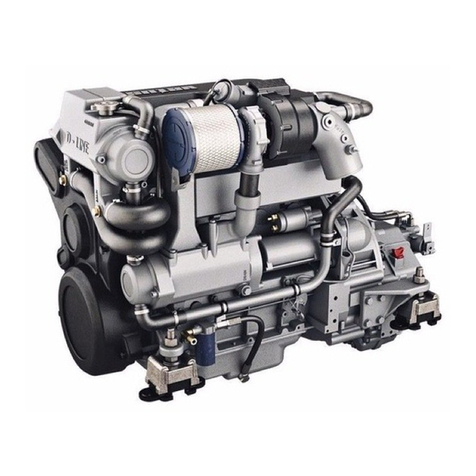
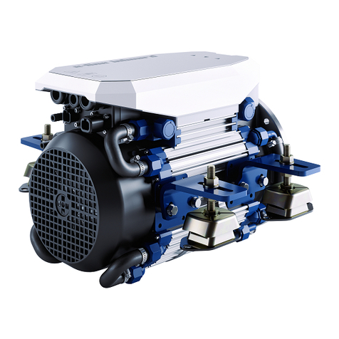
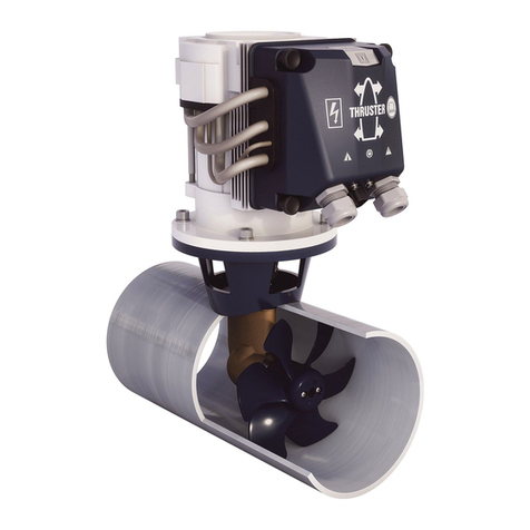
Vetus ELINE080 User manual

NEDERLANDS 7
ENGLISH 15
DEUTSCH 23
FRANÇAIS 31
ESPAÑOL 39
ITALIANO 47
DANSK 55
SVENSKA 63
NORSK 71
SUOMEKSI 79
POLSKI 87
370301.12
Copyright © 2023 VETUS B.V. Schiedam Holland
Installation manual
ELINE060 / ELINE080 / ELINE110
E-LINE electric propulsion
Installatiehandleiding
Installationshandbuch
Manuel d’ installation
Manual de instalación
Manuale d'installazione
Installationsvejledning
Installationsmanual
Installasjons handbook
Asennusopas
Instrukcja instalacji

2370301.12 Installation manual E-Line electric propulsion
Zorg er voor dat de eigenaar van het schip over deze handleiding kan beschikken.
Make sure that the user of the vessel is supplied with the owner’s manual.
Sorgen Sie dafür, daß dem Schiseigner die Gebrauchsanleitung bereitgestellt wird.
Veillez à ce que le propriétaire du bateau puisse disposer du mode d’emploi.
Asegurarse de que el propietario de la embarcación puede disponer de las instrucciones para el usuario.
Assicurarsi che il proprietario dell’imbarcazione disponga del manuale.
Sørg for, at denne brugsanvisning er til rådighed for skibets ejer.
Se till att båtens ägare har tillgång till bruksanvisningen.
Sørg for at skipets eier kan disponere over bruksanvisningen.
Käyttöohje tulee olla alusta käyttävien henkilöiden käytettävissä.
Upewnić się, że użytkownik statku jest zaopatrzony w instrukcję obsługi.
FR

370301.12 3
Installation manual E-Line electric propulsion
1 Veiligheid. . . . . . . . . . . . . . . . . . . . . . . . 7
2 Inleiding . . . . . . . . . . . . . . . . . . . . . . . . . 7
3 Installatieformulier. . . . . . . . . . . . . . . 8
4 Motorinstallatie. . . . . . . . . . . . . . . . . . 8
4.1 Motorfundatie. . . . . . . . . . . . . . . . . . . . 8
4.2 Motoropstelling . . . . . . . . . . . . . . . . . . 8
5 Schroefasinstallatie . . . . . . . . . . . . . . 9
5.1 Schroefaskoppeling. . . . . . . . . . . . . . . 9
5.2 Schroefas . . . . . . . . . . . . . . . . . . . . . . . . 9
5.3 Schroefraam. . . . . . . . . . . . . . . . . . . . . . 9
5.4 Schroef . . . . . . . . . . . . . . . . . . . . . . . . . . 9
6 Koeling . . . . . . . . . . . . . . . . . . . . . . . . 10
6.1 Buitenwaterkoeling (alleen
zoetwater) . . . . . . . . . . . . . . . . . . . . . 10
6.2 Kielkoeling . . . . . . . . . . . . . . . . . . . . . 10
6.3 Vullen koelsysteem . . . . . . . . . . . . . 11
6.4 Aansluitingen . . . . . . . . . . . . . . . . . . 11
7 Elektrisch systeem . . . . . . . . . . . . . 12
7.1 MCVB boosted charge functie . . . 12
7.2 Accu’s . . . . . . . . . . . . . . . . . . . . . . . . . . 12
7.3 Accucapaciteit. . . . . . . . . . . . . . . . . . 12
7.4 Accu installatie . . . . . . . . . . . . . . . . . 13
7.5 Hoofdstroomkabels. . . . . . . . . . . . . 13
7.6 Interne zekering . . . . . . . . . . . . . . . . 14
7.7 Conguratie een of meerdere
motoren . . . . . . . . . . . . . . . . . . . . . . . 14
7.8 Aansluiten CAN-bus
(stuurstroom) kabels . . . . . . . . . . . . 14
Inhoud Content Inhalt
1 Safety . . . . . . . . . . . . . . . . . . . . . . . . . 15
2 Introduction . . . . . . . . . . . . . . . . . . . 15
3 Installation form . . . . . . . . . . . . . . . 16
4 Motor installation . . . . . . . . . . . . . . 16
4.1 Motor support. . . . . . . . . . . . . . . . . . 16
4.2 Flexible mounting . . . . . . . . . . . . . . 16
5 Propeller shaft installation . . . . . 17
5.1 Propeller shaft coupling. . . . . . . . . 17
5.2 Propeller shaft . . . . . . . . . . . . . . . . . . 17
5.3 Propeller aperture . . . . . . . . . . . . . . 17
5.4 Propeller . . . . . . . . . . . . . . . . . . . . . . . 17
6 Cooling . . . . . . . . . . . . . . . . . . . . . . . . 18
6.1 Raw water cooling (fresh water
only) . . . . . . . . . . . . . . . . . . . . . . . . . . . 18
6.2 Keel cooling . . . . . . . . . . . . . . . . . . . . 18
6.3 Filling the cooling system . . . . . . . 19
6.4 Connections. . . . . . . . . . . . . . . . . . . . 19
7 Electrical System . . . . . . . . . . . . . . . 20
7.1 MCVB boosted charge function. . 20
7.2 Batteries . . . . . . . . . . . . . . . . . . . . . . . 20
7.3 Battery capacity . . . . . . . . . . . . . . . . 20
7.4 Battery installation. . . . . . . . . . . . . . 21
7.5 Main current cables . . . . . . . . . . . . . 21
7.6 Internal fuse. . . . . . . . . . . . . . . . . . . . 22
7.7 Conguration of one or more
motors . . . . . . . . . . . . . . . . . . . . . . . . . 22
7.8 Connecting CAN bus (control
current) cables. . . . . . . . . . . . . . . . . . 22
8 Hoofdafmetingen . . . . . . . . . . . . . . 95
9 Aansluitschema’s. . . . . . . . . . . . . . . 96
10 Accucapaciteit, accukabels . . . . 106
8 Principal dimensions . . . . . . . . . . . 95
9 Wiring diagrams . . . . . . . . . . . . . . . 96
10 Battery capacity, battery cables 106
1 Sicherheitsbestimmungen
. . . . . 23
2 Einleitung. . . . . . . . . . . . . . . . . . . . . . 23
3 Installationsformular . . . . . . . . . . . 24
4 Installation des Motors . . . . . . . . . 24
4.1 Motorhalterung . . . . . . . . . . . . . . . . 24
4.2 Flexible Montage . . . . . . . . . . . . . . . 24
5 Einbau der Propellerwelle . . . . . . 25
5.1 Kupplung der Propellerwelle . . . . 25
5.2 Propellerwelle . . . . . . . . . . . . . . . . . . 25
5.3 Propellerblende . . . . . . . . . . . . . . . . 25
5.4 Propeller . . . . . . . . . . . . . . . . . . . . . . . 25
6 Kühlung . . . . . . . . . . . . . . . . . . . . . . . 26
6.1 Rohwasser-Kühlung (nurfür
Süßwasser) . . . . . . . . . . . . . . . . . . . . . 26
6.2 Kielkühlung . . . . . . . . . . . . . . . . . . . . 26
6.3 Kühlsystems Befüllung . . . . . . . . . . 27
6.4 Anschlüsse . . . . . . . . . . . . . . . . . . . . . 27
7 Elektrisches System . . . . . . . . . . . . 28
7.1 MCVB verstärkte Ladefunktion. . . 28
7.2 Batterien . . . . . . . . . . . . . . . . . . . . . . . 28
7.3 Batteriekapazität . . . . . . . . . . . . . . . 28
7.4 Batterien Einbau . . . . . . . . . . . . . . . 29
7.5 Hauptstromkabel . . . . . . . . . . . . . . . 29
7.6 Interne Sicherung. . . . . . . . . . . . . . . 30
7.7 Anordnung von einem oder
mehreren Motoren. . . . . . . . . . . . . . 30
7.8 Anschließen von CAN-Bus
(Steuerstrom)-Kabeln . . . . . . . . . . . 30
8 Hauptabmessungen . . . . . . . . . . . 95
9 Schaltplan . . . . . . . . . . . . . . . . . . . . . 96
10 Akkukapazität, akkukabel . . . . . 106

4370301.12 Installation manual E-Line electric propulsion
Sommaire Índice Indice
8 Dimensiones principales . . . . . . . 95
9 Diagramas de cableado . . . . . . . . 96
10 Capacidad de las baterías, cables
de baterías. . . . . . . . . . . . . . . . . . . . 106
8 Dimensions principales. . . . . . . . . 95
9 Diagrammes de câblage. . . . . . . . 96
10 Capacité de la batterie, câbles
de batterie . . . . . . . . . . . . . . . . . . . . 106
8 Dimensioni principal . . . . . . . . . . . 95
9 Schemi Elettrici . . . . . . . . . . . . . . . . 96
10 Batterikapacitet, cavi della
batteria . . . . . . . . . . . . . . . . . . . . . . . 106
1 Sécurité
. . . . . . . . . . . . . . . . . . . . . . . 31
2 Introduction . . . . . . . . . . . . . . . . . . . 31
3 Formulaire d’installation . . . . . . . 32
4 Installation . . . . . . . . . . . . . . . . . . . . 32
4.1 Support Moteur . . . . . . . . . . . . . . . . 32
4.2 Montage exible. . . . . . . . . . . . . . . . 32
5 Installation de l’arbre d’hélice . . 33
5.1 Accouplement de l’arbre d’hélice 33
5.2 Arbre d’hélice . . . . . . . . . . . . . . . . . . 33
5.3 Cage de l’hélice. . . . . . . . . . . . . . . . . 33
5.4 Hélice. . . . . . . . . . . . . . . . . . . . . . . . . . 33
6 Refroidissement. . . . . . . . . . . . . . . . 34
6.1 Refroidissement à eau non-
traitée (eau douce uniquement) . 34
6.2 Refroidisseur de quille . . . . . . . . . . 34
6.3 Remplir le système de
refroidissement. . . . . . . . . . . . . . . . . 35
6.4 Raccords . . . . . . . . . . . . . . . . . . . . . . . 35
7 Système Électrique. . . . . . . . . . . . . 36
7.1 Fonction de charge stimulé MCVB 36
7.2 Batteries . . . . . . . . . . . . . . . . . . . . . . . 36
7.3 Capacité de la Batterie . . . . . . . . . . 36
7.4 Installation de la batterie . . . . . . . . 37
7.5 Câbles de courant principaux. . . . 37
7.6 Fusible interne. . . . . . . . . . . . . . . . . . 38
7.7 Conguration d'un ou plusieurs
moteurs. . . . . . . . . . . . . . . . . . . . . . . . 38
7.8 Connexion des câbles du Bus
CAN (courant de commande) . . . 38
1 Seguridad . . . . . . . . . . . . . . . . . . . . . 39
2 Introducción . . . . . . . . . . . . . . . . . . . 39
3 Formulario de instalación . . . . . . 40
4 Instalación del motor. . . . . . . . . . . 40
4.1 Soporte del motor . . . . . . . . . . . . . . 40
4.2 Montaje exible . . . . . . . . . . . . . . . . 40
5 Instalación del eje de la hélice . . 41
5.1 Acoplamiento del eje de la hélice 41
5.2 Eje de la hélice. . . . . . . . . . . . . . . . . . 41
5.3 Apertura de la hélice . . . . . . . . . . . . 41
5.4 Hélice. . . . . . . . . . . . . . . . . . . . . . . . . . 41
6 Refrigeración . . . . . . . . . . . . . . . . . . 42
6.1 Refrigeración de aguas crudas
(solo agua limpia). . . . . . . . . . . . . . . 42
6.2 Refrigeración en quilla . . . . . . . . . . 42
6.3 Rellenado del sistema de
refrigeración . . . . . . . . . . . . . . . . . . . 43
6.4 Conexiones. . . . . . . . . . . . . . . . . . . . . 43
7 Sistema eléctrico. . . . . . . . . . . . . . . 44
7.1 Función detonadora de carga
MCVB . . . . . . . . . . . . . . . . . . . . . . . . . . 44
7.2 Baterías . . . . . . . . . . . . . . . . . . . . . . . . 44
7.3 Battery capacity . . . . . . . . . . . . . . . . 44
7.4 Instalación de la batería . . . . . . . . . 45
7.5 Cables de la corriente principal . . 45
7.6 Fusible Intero. . . . . . . . . . . . . . . . . . . 46
7.7 Conguración de uno o más
motores. . . . . . . . . . . . . . . . . . . . . . . . 46
7.8 Conectar los cables CAN bus
(corriente de control) . . . . . . . . . . . 46
1 Sicurezza . . . . . . . . . . . . . . . . . . . . . . 47
2 Introduzione. . . . . . . . . . . . . . . . . . . 47
3 Modulo di istallazione. . . . . . . . . . 48
4 Installazione del motore. . . . . . . . 48
4.1 Supporto motore . . . . . . . . . . . . . . . 48
4.2 Montaggio essibile . . . . . . . . . . . . 48
5 Installazione dell'albero dell'elica 49
5.1 Accoppiamento dell'albero
dell'elica . . . . . . . . . . . . . . . . . . . . . . . 49
5.2 Albero dell'elica . . . . . . . . . . . . . . . . 49
5.3 Apertura dell'elica . . . . . . . . . . . . . . 49
5.4 Elica . . . . . . . . . . . . . . . . . . . . . . . . . . . 49
6 Rareddamento . . . . . . . . . . . . . . . 50
6.1 Rareddamento ad acqua grezza
(solo acqua dolce) . . . . . . . . . . . . . . 50
6.2 Rareddamento della chiglia . . . . 50
6.3 Riempimento del sistema di
rareddamento. . . . . . . . . . . . . . . . . 51
6.4 Collegamenti . . . . . . . . . . . . . . . . . . . 51
7 Impianto elettrico . . . . . . . . . . . . . . 52
7.1 Funzione di carica potenziata
MCVB . . . . . . . . . . . . . . . . . . . . . . . . . . 52
7.2 Batterie . . . . . . . . . . . . . . . . . . . . . . . . 52
7.3 Capacità della batteria . . . . . . . . . . 52
7.4 Installazione della batteria. . . . . . . 53
7.5 Cavi della corrente principale . . . . 53
7.6 Fusibile interno . . . . . . . . . . . . . . . . . 54
7.7 Congurazione di uno o più motori 54
7.8 Collegamento dei cavi CAN bus
(corrente di controllo). . . . . . . . . . . 54
370301.12 5
Installation manual E-Line electric propulsion
Indhold Innehåll Innhold
8 Mål . . . . . . . . . . . . . . . . . . . . . . . . . . . . 95
9 Strømskemaer . . . . . . . . . . . . . . . . . 96
10 Batteriets kapacitet,
Batterikabler. . . . . . . . . . . . . . . . . . 106
8 Huvudmått . . . . . . . . . . . . . . . . . . . . 95
9 Kopplingsscheman. . . . . . . . . . . . . 96
10 Battery capacity, Batterikablar. 106
1 Sikkerhed. . . . . . . . . . . . . . . . . . . . . . 55
2 Indledning. . . . . . . . . . . . . . . . . . . . . 55
3 Installationsskema . . . . . . . . . . . . . 56
4 Motorinstallation . . . . . . . . . . . . . . 56
4.1 Motorstøtte . . . . . . . . . . . . . . . . . . . . 56
4.2 Fleksibel montering. . . . . . . . . . . . . 56
5 Propellerakselinstallation . . . . . . 57
5.1 Propellerakslens kobling . . . . . . . . 57
5.2 Propelleraksel . . . . . . . . . . . . . . . . . . 57
5.3 Propellerblænde. . . . . . . . . . . . . . . . 57
5.4 Propeller . . . . . . . . . . . . . . . . . . . . . . . 57
6 Køling . . . . . . . . . . . . . . . . . . . . . . . . . 58
6.1 Råvandskøling (kun ferskvand) . . 58
6.2 Køl køling . . . . . . . . . . . . . . . . . . . . . . 58
6.3 Påfyldning af kølesystemet . . . . . . 59
6.4 Forbindelser. . . . . . . . . . . . . . . . . . . . 59
7 Elektrisk system. . . . . . . . . . . . . . . . 60
7.1 MCVB boostet opladningsfunktion 60
7.2 Batterier. . . . . . . . . . . . . . . . . . . . . . . . 60
7.3 Batterikapacitet. . . . . . . . . . . . . . . . . 60
7.4 Installation af batteri . . . . . . . . . . . . 61
7.5 Hovedstrømskabler . . . . . . . . . . . . . 61
7.6 Intern sikring . . . . . . . . . . . . . . . . . . . 62
7.7 Konguration af en eller ere
motorer . . . . . . . . . . . . . . . . . . . . . . . . 62
7.8 Tilslutning af CAN-buskabler
(kontrolstrøm) . . . . . . . . . . . . . . . . . . 62
1 Säkerhet . . . . . . . . . . . . . . . . . . . . . . . 63
2 Inledning . . . . . . . . . . . . . . . . . . . . . . 63
3 Installationsblankett . . . . . . . . . . . 64
4 Motorinstallation . . . . . . . . . . . . . . 64
4.1 Motorstöd. . . . . . . . . . . . . . . . . . . . . . 64
4.2 Flexibel montering. . . . . . . . . . . . . . 64
5 Installation av propelleraxel . . . . 65
5.1 Propelleraxelkoppling. . . . . . . . . . . 65
5.2 Kardanaxel . . . . . . . . . . . . . . . . . . . . . 65
5.3 Propelleröppning . . . . . . . . . . . . . . . 65
5.4 Propeller . . . . . . . . . . . . . . . . . . . . . . . 65
6 Kylning . . . . . . . . . . . . . . . . . . . . . . . . 66
6.1 Vattenkylning (endastfärskvatten) 66
6.2 Kölkylning. . . . . . . . . . . . . . . . . . . . . . 66
6.3 Påfyllning av kylsystemet. . . . . . . . 67
6.4 Anslutningar . . . . . . . . . . . . . . . . . . . 67
7 Elsystem . . . . . . . . . . . . . . . . . . . . . . . 68
7.1 MCVB-förstärkt laddningsfunktion 68
7.2 Batterier. . . . . . . . . . . . . . . . . . . . . . . . 68
7.3 Batterikapacitet. . . . . . . . . . . . . . . . . 68
7.4 Batteri-installation . . . . . . . . . . . . . . 69
7.5 Huvudströmkablar. . . . . . . . . . . . . . 69
7.6 Intern säkring . . . . . . . . . . . . . . . . . . 70
7.7 Konguration av en eller era
motorer . . . . . . . . . . . . . . . . . . . . . . . . 70
7.8 Ansluter CAN-buss (styrström)
kablar. . . . . . . . . . . . . . . . . . . . . . . . . . 70
8 Viktigste mål. . . . . . . . . . . . . . . . . . . 95
9 Koblingsskjemaer . . . . . . . . . . . . . . 96
10 Batterikapasitet, batterikabler. 106
1 Sikkerhet . . . . . . . . . . . . . . . . . . . . . . 71
2 Innledning
. . . . . . . . . . . . . . . . . . . . 71
3 Installasjonsskjema . . . . . . . . . . . . 72
4 Motor installasjon. . . . . . . . . . . . . . 72
4.1 Motor support. . . . . . . . . . . . . . . . . . 72
4.2 Fleksibel montering. . . . . . . . . . . . . 72
5 Installasjon av propellaksel. . . . . 73
5.1 Propellakselkobling . . . . . . . . . . . . . 73
5.2 Propellaksel . . . . . . . . . . . . . . . . . . . . 73
5.3 Propellåpning . . . . . . . . . . . . . . . . . . 73
5.4 Propell . . . . . . . . . . . . . . . . . . . . . . . . . 73
6 Kjøling. . . . . . . . . . . . . . . . . . . . . . . . . 74
6.1 Kjøling av råvann (kun ferskvann) 74
6.2 Kjølekjøling . . . . . . . . . . . . . . . . . . . . 74
6.3 Fylle kjølesystemet. . . . . . . . . . . . . . 75
6.4 Koblinger . . . . . . . . . . . . . . . . . . . . . . 75
7 Elektrisk system. . . . . . . . . . . . . . . . 76
7.1 MCVB-økt ladefunksjon . . . . . . . . . 76
7.2 Batterier. . . . . . . . . . . . . . . . . . . . . . . . 76
7.3 Batterikapasitet. . . . . . . . . . . . . . . . . 76
7.4 Batteri installasjon . . . . . . . . . . . . . . 77
7.5 Hovedstrømkabler . . . . . . . . . . . . . . 77
7.6 Innvendig sikring . . . . . . . . . . . . . . . 78
7.7 Kongurasjon av en eller ere
motorer . . . . . . . . . . . . . . . . . . . . . . . . 78
7.8 Koble til CAN bus
(kontrollstrøm) kabler . . . . . . . . . . . 78

6370301.12 Installation manual E-Line electric propulsion
Sisältö Spis tresciInhalt
8 Päämitat . . . . . . . . . . . . . . . . . . . . . . . 95
9 Kytkentäkaaviot . . . . . . . . . . . . . . . 96
10 Akkukapasiteetti, akkukaapelit 106
1 Turvallisuus. . . . . . . . . . . . . . . . . . . . 79
2 Esipuhe . . . . . . . . . . . . . . . . . . . . . . . . 79
3 Asennuslomake . . . . . . . . . . . . . . . . 80
4 Moottorin asennus . . . . . . . . . . . . . 80
4.1 Moottorin kannake . . . . . . . . . . . . . 80
4.2 Joustavat kiinnike. . . . . . . . . . . . . . . 80
5 Potkuriakselin asennus. . . . . . . . . 81
5.1 Potkuriakselin kytkin . . . . . . . . . . . . 81
5.2 Potkuriakseli. . . . . . . . . . . . . . . . . . . . 81
5.3 Potkurin ja veneen pohjan
välinen tila . . . . . . . . . . . . . . . . . . . . . 81
5.4 Potkuri . . . . . . . . . . . . . . . . . . . . . . . . . 81
6 Jäähdytys. . . . . . . . . . . . . . . . . . . . . . 82
6.1 Raakavesijäähdytys (vain
makeassa vedessä). . . . . . . . . . . . . . 82
6.2 Kölijäähdytys . . . . . . . . . . . . . . . . . . . 82
6.3 Jäähdytysjärjestelmän
täyttäminen . . . . . . . . . . . . . . . . . . . . 83
6.4 Liitännät . . . . . . . . . . . . . . . . . . . . . . . 83
7 Sähköjärjestelmä . . . . . . . . . . . . . . 84
7.1 MCVB (VMTL) -tehostettu
lataustoiminto. . . . . . . . . . . . . . . . . . 84
7.2 Akut . . . . . . . . . . . . . . . . . . . . . . . . . . . 84
7.3 Akkukapasiteetti. . . . . . . . . . . . . . . . 84
7.4 Akuston asennus . . . . . . . . . . . . . . . 85
7.5 Päävirtakaapelit . . . . . . . . . . . . . . . . 85
7.6 Sisäinen sulake . . . . . . . . . . . . . . . . . 86
7.7 Yhden tai useamman moottorin
kokoonpano. . . . . . . . . . . . . . . . . . . . 86
7.8 CAN-väylän (ohjausvirran)
kaapeleiden liittäminen . . . . . . . . . 86
1 Bezpieczeństwo. . . . . . . . . . . . . . . . 87
2 Wprowadzenie . . . . . . . . . . . . . . . . . 87
3 Formularz instalacji . . . . . . . . . . . . 88
4 Instalacja silnika . . . . . . . . . . . . . . . 88
4.1 Wsparcie silnika. . . . . . . . . . . . . . . . . 88
4.2 Elastyczny montaż . . . . . . . . . . . . . . 88
5 Montaż wału napędowego . . . . . 89
5.1 Sprzęgło wału napędowego. . . . . 89
5.2 Wał napędowy . . . . . . . . . . . . . . . . . 89
5.3 Szczelina śruby napędowej . . . . . . 89
5.4 Śruba napędowa . . . . . . . . . . . . . . . 89
6 Chłodzenie. . . . . . . . . . . . . . . . . . . . . 90
6.1 Chłodzenie wodą surową (tylko
woda słodka) . . . . . . . . . . . . . . . . . . . 90
6.2 Chłodnica kilowa . . . . . . . . . . . . . . . 90
6.3 Napełnianie układu chłodzenia . . 91
6.4 Połączenia. . . . . . . . . . . . . . . . . . . . . . 91
7 Układ elektryczny . . . . . . . . . . . . . . 92
7.1 Funkcja MCVB boosted charge. . . 92
7.2 Akumulatory . . . . . . . . . . . . . . . . . . . 92
7.3 Pojemność akumulatorów. . . . . . . 92
7.4 Instalacja akumulatorów . . . . . . . . 93
7.5 Główne przewody elektryczne. . . 93
7.6 Bezpiecznik wewnętrzny . . . . . . . . 94
7.7 Konguracja jednego lub
większej ilości silników . . . . . . . . . . 94
7.8 Podłączanie przewodów
magistrali CAN. . . . . . . . . . . . . . . . . . 94
8 Główne wymiary . . . . . . . . . . . . . . . 95
9 Schemat okablowania. . . . . . . . . . 96
10 Pojemność akumulatora, kable
akumulatora . . . . . . . . . . . . . . . . . . 106

370301.12 7
Installation manual E-Line electric propulsion
1 Veiligheid
Waarschuwingsaanduidingen
Indien van toepassing worden in deze handleiding in verband met
veiligheid de volgende waarschuwingsaanduidingen gebruikt:
Gevaar
Geeft aan dat er een groot potentieel gevaar aanwezig is dat ernstig
letsel of de dood tot gevolg kan hebben.
WaarschuWinG
Geeft aan dat er een potentieel gevaar aanwezig is dat letsel tot ge-
volg kan hebben.
voorzichtiG
Geeft aan dat de betreende bedieningsprocedures, handelingen,
enzovoort, letsel of fatale schade aan de machine tot gevolg kunnen
hebben. Sommige VOORZICHTIG-aanduidingen geven tevens aan
dat er een potentieel gevaar aanwezig is dat ernstig letsel of de dood
tot gevolg kan hebben.
Let op
Legt de nadruk op belangrijke procedures, omstandigheden, enzo-
voort.
Symbolen
Geeft aan dat de betreende handeling moet worden uit-
gevoerd.
Geeft aan dat een bepaalde handeling verboden is.
Deel deze veiligheidsinstructies met alle gebruikers.
Algemene regels en wetten met betrekking tot veiligheid en ter voor-
koming van ongelukken dienen altijd in acht te worden genomen.
WaarschuWinG
Dit product mag alleen worden geïnstalleerd en onderhouden
door gekwaliceerd personeel dat de instructies en voorzorgs-
maatregelen in deze handleiding hebben gelezen en begre-
pen. Het niet opvolgen van de instructies in deze handleiding
kan leiden tot ernstig letsel of materiële schade. De fabrikant
is niet aansprakelijk voor schade als gevolg van onjuiste instal-
latie of onderhoud door niet-gekwaliceerd personeel.
Het E-DRIVE systeem bestaat uit vijf modules:
- Voortstuwing
- Bediening
- Energiebewaking
- Energie-opslag
- Energietoevoer
Binnen deze modules zijn meerdere keuzes en combinaties mogelijk.
Let op
Raadpleeg de installatiehandleidingen van alle onderdelen
alvorens u het E-DRIVE systeem in gebruik neemt.
Eigenmachtige wijzigingen sluiten de aansprakelijkheid van de
fabriek voor de daaruit voortvloeiende schade uit.
Afhankelijk van windvang, waterverplaatsing, schroef, accupakket
grootte en vorm van het onderwaterschip zal het door de elektromotor
geleverde vermogen op ieder schip een verschillend resultaat geven.
Het nominaal opgegeven vermogen is alleen haalbaar onder opti-
male omstandigheden:
• Zorg tijdens gebruik voor een correcte accuspanning.
• De installatie is uitgevoerd met inachtname van de aanbevelin-
gen zoals gegeven in deze installatieinstructie, in het bijzonder
met betrekking tot:
- Voldoende grootte van de draaddoorsnede van de accukabels,
om zodoende het spanningsverlies zo veel mogelijk beperkt
te houden.
- De aanstroom naar de schroef.
- Uitlijning van het schroefas systeem.
WaarschuWinG
Werk nooit aan de elektrische installatie terwijl het systeem
onder spanning staat.
WaarschuWinG
Verwisselen van de plus ‘+’ en min‘—’ brengt onherstelbare
schade toe aan de installatie!
Let op
Controleer op mogelijke lekkage onmiddellijk nadat het
schip te water is gelaten.
Let op
Controleer na de installatie van het systeem, voor
inbedrijfstelling, de volgende punten:
- Flexibele motorsteunen
- Koelvloeistof lekkage
- Alle slang- en kabelverbindingen, bouten, moeren en wartels
NEDERLANDS
2 Inleiding
Deze handleiding geeft richtlijnen voor de inbouw van de VETUS
E-LINE elektromotor, type‘ELINE060’, ‘ ELINE080 en ‘ELINE110’.
De kwaliteit van de inbouw is maatgevend voor de betrouwbaarheid
van het E-DRIVE systeem. Bijna alle storingen die naar voren komen
zijn terug te leiden tot fouten of onnauwkeurigheden bij de inbouw.
Het is daarom van het grootste belang de in de installatieinstructies
genoemde punten tijdens de inbouw volledig op te volgen en te
controleren.

8370301.12 Installation manual E-Line electric propulsion
3 Installatieformulier
Ga naar www.vetus.com en download het installatieformulier.
Let op
Om aanspaak te kunnen maken op garantie vul het
installatieformulier
volledig in en stuur deze naar:
installationforms@vetus.com
Het serienummer van de MCVB (Motor Controller VETUS Boosted
Charge function) is op de volgende locatie aangebracht:
Let op
De motor moet worden geïnstalleerd in een droge, goed ge-
ventileerde ruimte.
De installatie moet te allen tijde vrij blijven van bilge water.
De omgevingstemperatuur mag niet hoger worden dan 50 °C.
Zorg voor voldoende ventilatie. Voer koele lucht aan en voer
warme lucht af.
4.1 Motorfundatie
Alle onderdelen van het voorstuwingssysteem moeten correct zijn
uitgelijnd om een goede werking te waarborgen. De fundatie moet
voldoende stijf zijn om dit onder alle omstandigheden te garanderen.
Let op
De E-LINE motor is ontworpen om de door de schroef opgewek-
te stuwkracht te weerstaan. Een stuwdruklager is niet nodig.
Houdt bij het bepalen van de afmetingen van de fundatie rekening
met een vrije ruimte van tenminste 10 mm tussen de motor en de
fundatie.
De oplegvlakken van de motorsteunen moeten in het zelfde vlak lig-
gen. Dit om vervorming van de rubberelementen van de exibele
motorsteunen te voorkomen.
Voor de voor- en achterzijde van de motoropstelling geldt dat de in-
drukking links en rechts gelijk moet zijn. Tussen de voor en achterzij-
de is een verschil in indrukking toegestaan en veelal onvermijdelijk.
• Plaats de motor op de motorsteunen en wacht 48 uur voordat met
het uitlijnen wordt begonnen. Als het niet mogelijk is te wachten
stel dan de steunen zo af dat de motor 0,75 mm te hoog staat.
4 Motorinstallatie
0
-1
+1
0
-1
+1
0°
0°
- 8°
+ 8°
+ 8°
- 8°
4.2 Motoropstelling
De exibele opstelling is speciaal aangepast aan de karakteristiek
van de motor. Gebruik de meegeleverde exibele motorsteunen (tril-
lingdempers); deze zijn speciaal ontwikkeld voor elektrische voort-
stuwingsmotoren.
De trillingdempers moeten in langsrichting spanningsvrij gemon-
teerd kunnen worden. Vervormde trillingdempers kunnen trillingen
en geluid aan het schip overdragen.
De montagebeugels zijn eenvoudig in hoogte verstelbaar en in een
hoek van 0° of 8° in te stellen. Dit maakt hermotorisering en het aan-
sluiten op een bestaande schroefas eenvoudig.
Let op
Bij ontvangst staan de motorbeugels in de transport stand.
Demonteer de beugels, draai deze een halve slag en monteer
ze weer.

370301.12 9
Installation manual E-Line electric propulsion
A
A
B
B
A = A
B = B
De juiste instelling van de trillingdempers kan als volgt worden ge-
realiseerd:
• Stel de motor ongeveer in lijn met de schroefas met behulp van
de roestvaststalen montagebeugels en de stelmoeren op de tril-
lingsdempers. De schroefas nog niet verbinden met de klemnaaf
van de koppeling.
• Licht de motor aan de voorzijde iets op zodat beide voorsteunen
los komen van de moeren van de trillingdempers.
• Laat de motor zakken en verstel de moeren zodanig dat beide
motorsteunen gelijktijdig op de moeren komen te rusten.
• Herhaal dit voor de achterzijde van de motor.
• Na het juist instellen van de trillingdempers kan het uitlijnen van
de motor worden uitgevoerd door voor of achter beide stelmoe-
ren, zowel links als rechts, exact evenveel slagen te verdraaien.
• Zet de moeren vast met het aangeven koppel.
min. 10 min. 10
max. 60
0.15 D
0.15 D
D
5.3 Schroefraam
- Voor de ruimte tussen het vlak en de toppen van de schroefbla-
den geldt een minimale afstand van 15% van de diameter van de
schroef.
5 Schroefasinstallatie
5.4 Schroef
De schroef en het schroefraam zijn zeer belangrijk voor de vaarei-
genschappen van het schip. In het bijzonder bij een schip met elek-
trische voortstuwing dient de schroef optimaal op het schip te zijn
afgestemd.
Raadpleeg uw VETUS dealer voor het kiezen van de juiste schroef.
Er kan gekozen worden voor zowel een links- als rechtsdraaiende
schroef. Via het controle paneel kan de draairichting van de motor
worden gekoppeld aan de beweging van de bediening, zodat voor-
waardse bediening ook resulteert in een voorwaardse beweging van
de boot.
75 Nm
(7.7 kgm, 55.3 ft.lbf)
M12 x 1.75
- De afstand van de schroefnaaf tot het buitenlager mag minimaal
10 mm tot maximaal 60 mm bedragen.
- Aan de voor- en achterzijde van de schroefbladen moet het water
over een afstand van tenminste 10 cm vrij kunnen toestromen.
- Voor werkzaamheden aan de motor of schroefasinstallatie is het
nuttig als de as zo'n 10 cm naar achter geschoven kan worden.
5.1 Schroefaskoppeling
Verbind de E-LINE motor met de schroefas met behulp van een exi-
bele koppeling van het type VETUS Combiex (1225/1230) of Bullex
(0125/011).
5.2 Schroefas
VETUS raadt aan een schroefas te installeren met een diameter van
ten minste 25 mm.
In verband met de axiale beweging van de schroefas moet er een
minimale vrije ruimte zijn tussen:
- het buitenlager en de naaf van de scheepsschroef,
- het binnenlager en de naaf van de koppeling.
- Borg de schroefasdopmoer met een borgplaat
NEDERLANDS
Let op
Het is van groot belang dat de E-LINE motor en de schroefas
in één lijn staan. Controleer de uitlijning nogmaals als de boot
in het water ligt.

10 370301.12 Installation manual E-Line electric propulsion
WL
min. 15 cm
6.1 Buitenwaterkoeling (alleen zoetwater)
Bij deze manier van koelen stroomt er buitenwater door het systeem.
Warmte wordt direct afgevoerd aan het buitenwater.
• Gebruik voor het lteren van buitenwater altijd waterlter FTR140
in combinatie met het jnmazige lterelement FTR140FM.
• Monteer het waterlter en de waterafvoer altijd boven de water-
lijn. Bevestig het waterlter tegen een verticaal schot.
• Installeer op het waterinlaatschepje altijd een buitenboordafslui-
ter!
• Pas voor beide verbindingen, waterinlaatschepje naar waterlter
en waterlter naar motor, altijd exibele slang toe.
• Controleer het waterlter voor elk gebruik en maak het lter in-
dien nodig schoon.
1
3
6
5
2
7
4
6.2 Kielkoeling
Bij deze manier van koelen circuleert er koelvloeistof door het sys-
teem.Warmte wordt afgevoerd aan het buitenwater via de kielkoeler.
1 Kielkoeler
2 Kielkoeler IN
3 Kielkoeler UIT
4 Koelvloeistof motor IN
5 Circulatiepomp
6 Koelvloeistof motor UIT
7 Waterlter/Expantie tank
Kielkoeler
De kielkoeler (1) moet, aan de buitenzijde, tegen de bodem van de
romp geplaatst worden.
Houdt bij het kiezen van een plaats van de kielkoeler met het vol-
gende rekening:
- De kielkoeler moet daar worden geplaatst waar een continue
langsstromen van water onder alle omstandigheden is gewaar-
borgd.
- Nabij de boeg, waar bij hogere snelheden turbulentie kan voorko-
men, is een minder geschikte plaats.
6 Koeling
Om een zo hoog mogelijk rendement te verkrijgen worden de elek-
tromotor en motor controller door vloeistof gekoeld.
Er zijn twee opties:
- Buitenwaterkoeling
- Kielkoeling
Sluit de koelwaterslangen, 12 mm, afhankelijk van de E-LINE uitvoe-
ring, als volgt op de motor aan:
ELINE080
ELINE110
ELINE060

370301.12 11
Installation manual E-Line electric propulsion
B
A
170 mm
ø 28 mm
max. 35 mm
6.3 Vullen koelsysteem
• Verwijder het deksel van de expansietank (7). Vul het koelsysteem.
Gebruik een mengsel van 40% anti-vries (op ethyleen-glycol
basis) en 60% schoon leidingwater en koelvloeistof of gebruik
100% koelvloeistof.
• Vul zover bij tot de expansietank voor ca. de helft gevuld is.
Expansietank
• Monteer de expansietank (7) op een goed bereikbare plaats
boven het hoogste niveau van de elektromotor.
• Pas voor de verbindingen tussen kielkoeler, expansietank en
motor altijd een exibele slang toe; met een inwendige diameter
van 12mm.
• Houdt de slangen zo kort mogelijk en zorg ervoor dat de slangen
zo min mogelijk bochten bevatten.
• Gebruik uitsluitend water en/of zeep, dus geen vet- of oliehou-
dende producten, om het monteren van de slang op de slangaan-
sluitingen te vereenvoudigen.
• Monteer de slangverbinding met, roestvaststalen, slangklemmen
- De kielkoeler moet ook onder water
blijven wanneer het schip rolt.
- Monteer de kielkoeler met de mee-
geleverde pakkingringen (A), de rin-
gen (B) en de moeren.
• Gebruik een afdichtmiddel bij de
montage van de kielkoeler tegen de
scheepshuid.
6.4 Aansluitingen
Let op
Controleer na de installatie van het koelwatersysteem, voor
inbedrijfstelling, de volgende punten:
- Koelvloeistof lekkage
- Alle slang- en kabelverbindingen, bouten, moeren en war-
tels, inclusief de aansluitingen op de E-LINE motor.
NEDERLANDS
7
FRONT

12 370301.12 Installation manual E-Line electric propulsion
+ 48 V
CAN-bus
MCVB Boosted charge
+ 24 V
- 48 V
CAN-bus
+ 48 V
- 48 V
MCVB
Boosted charge
+ 24 V
8 - 10 Nm
7 Elektrisch systeem
De elektrische bedrading tussen de elektromotor en de motor con-
troller is reeds aangebracht. De installatie is massavrij.
Sluit de motor als volgt aan:
WaarschuWinG
De MCVB boosted charge functie is standaard alleen geschikt
voor Lood zuur accu's
7.2 Accu’s
De accuspanning dient 48 V nominaal te zijn, met een bedrijfsbereik
tussen ≥44 V en ≤59 V. Met een absoluut maximum van 60 V.
De geïntegreerde motorregelaar beperkt het vermogen vanaf 44 V
en stopt bij 40 V. Te diepe ontlading van de accu wordt hiermee voor-
komen.
Startaccu’s zijn niet geschikt voor een elektrische voortstuwingsin-
stallatie. In plaats daarvan moeten semi-tractieaccu’s of tractieaccu’s
worden gebruikt.
VETUS kan verschillende onderhoudsvrije accu's leveren. Bijvoor-
beeld type AGM (Absorbed Glass Mat), DeepCycle of lithium 4-cel
LiFePO4 zijn geschikt voor elektrische voortstuwing.
Let op
Houd de spanning van serie geschakelde accu’s in evenwicht.
Controleer individuele accu blokken en zorg dat de spanning
onderling gelijk is.
7.3 Accucapaciteit
Bij de bepaling van de accucapaciteit spelen de volgende punten
een belangrijke rol:
- Eigenschappen schip (lengte waterlijn, gewicht, rompvorm)
- Vaarstijl
- Gewenste actieradius (vaartijd vs snelheid)
- Accu type
Tabel 'Indicatie opgenomen vermogen waterverplaatsend schip'
op pagina 14 geeft een indicatie van het opgenomen vermogen
(energieverbruik) van een waterverplaatsend schip bij verschillende
lengtes en snelheden. Met het opgenomen vermogen kan vervol-
gens de vaartijd worden berekend. Zie onderstaand voorbeeld:
1. Bepalen accucapaciteit
Voor een boot met een lengte van 6 meter en een gewenste vaar-
snelheid van 8,8 km/u (4,7 kn) geldt een indicatief opgenomen
vermogen van 2,1 kW. De gewenste vaartijd stellen we op mini-
maal 6 uur, continue varend. Hieruit volgt een benodigde accuca-
paciteit van 2,1 x 6 = 12,6 kWh.
2. Bepalen accupakket
Een accupakket van acht AGM accu's, max. diepte onlading van
70%, C20 waarde 220 Ah, 12 V serie-parallel (4 x 12 V en 2 x 220
Ah) geschakeld tot een 48 V accupakket geeft een bruikbare ac-
cucapaciteit van ((220 x 2) x (4 x 12) x 70%) = 14,8 kWh.
3. Berekenen vaartijd (indicatie)
Op basis van het energieverbruik van 2,1 kW geeft dit een vaartijd
van (14,8 / 2,1) ruim 7 uur.
WaarschuWinG
Houdt accu kabels vrij van de E-LINE behuizing en scherpe
randen
WaarschuWinG
Verbind alle negatieve geleiders! Een zwevende min
veroorzaakt systeemfouten!
WaarschuWinG
Een (systeem) spanning hoger dan 60 V brengt onherstelbare
schade toe aan de installatie!
7.1 MCVB boosted charge functie
Met behulp van de MCVB boosted charge functie kan de 48 Volt
E-LINE motor worden gebruikt in een (bestaand) 24 Volt boordnet.
Door een 24 Volt accubank te verbinden met de MCVB boosted char-
ge aansluiting wordt de 48 Volt, E-LINE, accubank geladen. Een extra
laadvoorziening is niet nodig.
Zie pagina 96 voor het aansluitschema.

370301.12 13
Installation manual E-Line electric propulsion
7.4 Accu installatie
Bij het opstellen van de accu’s moet met het volgende rekening wor-
den gehouden:
WaarschuWinG
Volg de waarschuwingen en veiligheidsvoorschriften, zoals
deze in de handleiding van de accu zijn vermeld, op.
- Accu’s moeten worden geïnstalleerd in een droge, goed geventi-
leerde ruimte.
- Ventilatie is belangrijk aangezien kleine hoeveelheden explosief
gas kunnen worden geproduceerd tijdens het laden. Installeer
eventueel een systeem voor geforceerde ventilatie.
- Plaats de accu’s boven het bilge water niveau.
- Accu’s moeten stevig worden vast gezet om schade aan de behui-
zing te voorkomen. Plaats accu’s bij voorkeur in een bak.
- De omgevingstemperatuur mag niet hoger worden dan 60°C.
Plaats de accu’s nooit in direct zonlicht!
- Accu’s moeten goed toegankelijk zijn voor onderhoud.
- Plaats geen schakelaars of andere elektrische apparatuur in de
buurt van de accu’s. Mogelijke vonken kunnen een explosie ver-
oorzaken.
- Voorkom dat metalen voorwerpen per ongeluk in contact kunnen
komen met een accupool.
7.5 Hoofdstroomkabels
• Sluit de motor aan op de accu’s zoals in de schema’s is aangege-
ven, zie pagina 96.
• Neem in de ‘+’ kabel de meegeleverde zekering en een hoofd-
schakelaar op.
WaarschuWinG
Houd bij de berekening van de kabel doorsnedes rekening
met een maximaal toelaatbare spanningsval van 5%.
Gebruik nooit kleinere kabel doorsnedes dan aangegeven in
onderstaande tabel.
Motor type E-LINE 060 E-LINE 080 E-LINE 110
Maximaal
ingangsvermogen 7,3 kW 10,2 kW 13,3 kW
Accukabel 50 mm270 mm295 mm2
Zekering 200 A 250 A 300 A
Als de accu’s niet worden gebruikt c.q. niet worden geladen verdient
het de voorkeur deze van elkaar los te koppelen middels een zoge-
naamde scheidingsschakelaar.
WaarschuWinG
Plaats de zekering, de hoofdschakelaar en eventuele
scheidingsschakelaars NOOIT in de accuruimte!
Raadpleeg bij de aanleg van de elektrische installatie altijd
de lokaal geldende regelgeving.
Bij het installeren van de accukabels moet met volgende rekening
worden gehouden:
- Voer de accukabels langs de kortst mogelijke weg van de accu’s
naar de motor.
- Bundel de‘+’en ‘—’kabel bij een lange kabellengte.
- Installeer de ‘+’ en ‘—’ kabels bij voorkeur zodanig dat de totale
kabelafstand van elke accu gelijk is. Dit zorgt voor een gelijke be-
lasting voor elke accu.
- Zorg er voor dat de kabels niet door aanwezig bilge water lopen.
- Zorg er voor dat de kabel geen contact maakt met scherpe ran-
den.
- Zet de kabels vast om slijtage of doorslijten ten gevolge van trillen
van het schip te voorkomen.
- Gebruik kabelschoenen om de kabels aan de schakelaars, zeke-
ring en motor aan te sluiten.
- Breng deze kabelschoenen bij voorkeur aan door middel van per-
sen (krimpen)
- Gebruik het juiste formaat poolklemmen om de kabels aan de ac-
cupolen aan te sluiten
- Zet de bouten goed vast om een goede verbinding te verkrijgen.
- Gebruik geen veerbelaste poolklemmen!
- Vet de accupolen en poolklemmen in met zuurvrije vaseline of ac-
cupolenvet om corrosie te voorkomen.
- Verwissel nooit de aansluitkabels.
- Controleer voor vertrek de ladingstoestand van de accu's net
zoals u bij een dieselmotor de tankinhoud zou controleren.
WaarschuWinG
Verwisselen van de plus ‘+’ en min ‘—’ brengt onherstelbare
schade toe aan de installatie!
WaarschuWinG
Sluit NOOIT de accu’s nooit kort door het verbinden van de
plus‘+’ pool met de min‘—’ pool.
Aansluiten hoofdstroomkabels
• Schakel alle stroomverbruikers uit.
• Vermijd kortsluiting veroorzaakt door bijvoorbeeld gereedschap.
• Sluit eerst de pluskabel aan en dan de massakabel.
NEDERLANDS

14 370301.12 Installation manual E-Line electric propulsion
1
2
PCB
PCB
• Verwijder de kap en zet de schakelaar om. Deze bevindt zich aan
de onderzijde van het printplaatje (PCB). Draai eventueel de bou-
ten en moeren van de PCB houder tijdelijk los.
• Verplaats de schakelaar van stand 1 naar stand 2. De E-LINE motor
is nu gecongureed voor gebruik in een systeem met meerdere
motoren.
• Plaats de kap weer terug.
Let op
De draairichting van de motor kan worden ingesteld op het
bedieningspaneel.
7.8 Aansluiten CAN-bus (stuurstroom) kabels
Zie schema’s vanaf pagina 99 indien er meerdere panelen moeten
worden aangesloten.
Let op
De CAN-bus voeding moet altijd op 12 Volt (≥10 V, ≤16 V)
worden aangesloten. Gebruik als voeding het E-DRIVE
MPE1KB contactslot.
voorzichtiG
Zoals de internationale normen voorschrijven, moeten alle
neutrale (negatieve) geleiders van het gelijkstroomsysteem
op één centraal punt worden verbonden. Dit voorkomt niet
alleen gevaarlijke situaties en corrosieproblemen, maar ook
foutmeldingen in het CAN-bussysteem.
Let op
Bij vervanging uitsluitend een zekering met dezelfde
waarde toepassen.
7.7 Conguratie een of meerdere motoren
Standaard is de E-LINE motor gecongureerd voor toepassing in een
voortstuwingssyteem met één motor. Alleen als meerdere motoren
worden geinstalleerd moet de instelling van één van de E-LINE moto-
ren worden gecongureerd.
Gevaar
Werk alleen aan het systeem bij stilstaande motor en uitge-
schakeld elektrisch systeem.
7.6 Interne zekering
In de aansluitkast bevindt zich op de regelaar een interne zekering.
Deze zekering beschermd de regelaar en de motor tegen kortsluiting
of overbelasting.
Indicatie opgenomen vermogen waterverplaatsend schip
Lengte waterlijn 4 m (13 feet) 6 m (19,8 feet) 8 m (26,5 feet) 10 m (33 feet) 12 m (40 feet) 14 m (46 feet)
Rustig varend 6 km/u 6 km/u 6 km/u 6 km/u 6 km/u 6 km/u
0,9 kW 0,7 kW 0,8 kW 1 kW 1,1 kW 1,2 kW
Kruissnelheid 6,3 km/u 7,7 km/u 8,9 km/u 10 km/u 11,0 km/u 11,8 km/u
1,1 kW 1,4 kW 2,6 kW 4,6 kW 6,5 kW 9,1 kW
Rompsnelheid 9 km/u 11 km/u 12,8 km/u 14,3 km/u 15,7 km/u 16,8 km/u
3,1 kW 4,1 kW 7,7 kW 13,4 kW 18,9 kW 26,5 kW

370301.12 15
Installation manual E-Line electric propulsion
ENGLISH
1 Safety
Warning indications
Where applicable, the following warning indications are used in this
manual in connection with safety:
DanGer
Indicates that great potential danger exists that can lead to serious
injury or death.
WarninG
Indicates that a potential danger that can lead to injury exists.
caution
Indicates that the usage procedures, actions etc. concerned can re-
sult in serious damage to or destruction of the engine. Some CAU-
TION indications also advise that a potential danger exists that can
lead to serious injury or death.
note
Emphasises important procedures, circumstances etc.
Symbols
Indicates that the relevant procedure must be carried out.
Indicates that a particular action is forbidden.
Share these safety instructions with all users.
General rules and laws concerning safety and accident prevention
must always be observed.
WarninG
This product should only be installed and maintained by
qualied personnel who have read and understood the
instructions and precautions in this manual. Failure to follow
the instructions in this manual may result in serious injury or
property damage. The manufacturer shall not be liable for any
damages resulting from improper installation or maintenance
by unqualied personnel.
2 Introduction
This manual gives guidelines for installing a VETUS E-LINE electric
motor, type ‘ELINE060’, ‘ ELINE080 and ‘ELINE110’.
The quality of the installation is decisive for the reliability of the E-
LINE system. Almost all faults can be traced back to errors or inac-
curacies during installation. It is therefore imperative that the steps
given in the installation instructions are followed in full during the
installation process and checked afterward.
The E-DRIVE system consists of ve modules:
- Propulsion
- Control
- Energy monitoring
- Energy storage
- Energy supply
Several choices and combinations are possible within these modules.
note
Refer to the installation manuals of all components before
using the E-DRIVE system.
Unauthorised modications exclude the factory's liability for any
resulting damage.
Depending on wind area, displacement, propeller, battery pack size
and shape of the underwater hull, the power delivered by the electric
motor will give a dierent result on each vessel.
The nominal rated power output is only achievable under optimum
conditions:
• During use ensure the correct battery voltage is available.
• The installation is carried out in compliance with the recommen-
dations given in this installation instruction, in particular with re-
gard to:
- Suciently large diameter of the battery cables so that voltage
drop is reduced to a minimum.
- The inow to the propeller.
- Alignment of the propeller shaft system.
WarninG
Never work on the electrical system while it is energized.
WarninG
Changing over the plus (+) and minus (-) connections will
cause irreparable damage to the installation.
note
Check for possible leakage immediately after the ship has
been launched.
note
After installation of the system, before commissioning,
check the following points:
- Flexible motor mounts.
- Coolant leakage.
- All hose and cable connections, bolts, nuts and glands.

16 370301.12 Installation manual E-Line electric propulsion
3 Installation form
Go to www.vetus.com and download the installation form.
note
In order to make a warranty claim, please complete
the installation form in full and send the form to:
installationforms@vetus.com
The serial number of the MCVB (Motor Controller VETUS Boosted
Charge function) is located at the following location:
note
The motor should be installed in a dry, well-ventilated area.
The installation must be kept free of bilge water at all times.
The ambient temperature should not exceed 50 °C. Ensure ade-
quate ventilation. Supply cool air and discharge warm air.
4.1 Motor support
All components of the propulsion system must be properly aligned
to ensure correct operation.
The foundation must be suciently rigid to maintain this under all
conditions.
note
The E-LINE motor is designed to withstand the thrust gener-
ated by the propeller. A thrust bearing is not necessary.
When determining the dimensions of the foundation, take into ac-
count a clearance of at least 10 mm (3/8") between the motor and
the foundation.
The mounting surfaces of the motor supports must all be at the same
level. This will prevent distortion of the rubber elements of the ex-
ible motor supports.
For the front and rear of the motor setup, the compression on the left
and right must be the same. A dierence in compression between
the front and rear is permitted and often unavoidable.
• Place the motor on the motor supports and wait 48 hours before
starting the alignment. If it is not possible to wait that long, set the
supports so that the motor is 0.75 mm (1/32") too high.
4.2 Flexible mounting
The exible installation is specially adapted to the characteristics of
the motor. Use the supplied exible motor supports (vibration damp-
ers); these have been specially developed for electric propulsion en-
gines.
The vibration dampers must be tted without tension in the longitu-
dinal direction. Distorted vibration dampers can transmit vibration
and noise to the boat.
The mounting brackets are easily adjustable in height and at an
angle of 0° or 8°. This makes re-motorisation and connection to an
existing propeller shaft easy.
note
Upon receipt, the motor brackets are in the transport position.
Dismantle the brackets, turn them half a turn and reassemble
them.
4 Motor installation
0
-1
+1
0
-1
+1
0°
0°
- 8°
+ 8°
+ 8°
- 8°

370301.12 17
Installation manual E-Line electric propulsion
ENGLISH
A
A
B
B
A = A
B = B
note
It is very important that the E-LINE motor and the propeller
shaft are in line. Check the alignment again when the boat is
in the water.
Correct adjustment of the vibration dampers can be achieved as fol-
lows:
• Set up the motor so that it is more or less in line with the propeller
shaft, using the adjuster nuts on the vibration dampers, do NOT
yet connect the propeller shaft with the hub of the coupling.
• Lift the motor at the front so that both front supports just come
free of the vibration damper nuts.
• Lower the motor again and adjust the nuts so that both motor
supports rest on the nuts at the same time.
• Repeat this at the rear end of the motor.
• When the vibration dampers have been adjusted correctly, the
motor can be aligned by turning both the adjuster nuts fore and
aft, left and right, exactly the same number of turns.
• Tighten the nuts to the torque indicated.
min. 10 (
3
/
8
”) min. 10 (
3
/
8
”)
max. 60 (2
3
/
8
”)
0.15 D
0.15 D
D
5.3 Propeller aperture
- The space between the tips of the propeller blades and the bot-
tom of the boat should be at least 15% of the propeller diameter.
5 Propeller shaft installation
5.4 Propeller
Design of the propeller and propeller aperture are very important for
the cruising characteristics of the vessel. It is especially important for
a vessel with electrical propulsion that the propeller size is selected
correctly.
Consult your VETUS dealer to choose the correct propeller.
You can choose for both a left and right turning screw. Via the con-
trol panel, the direction of rotation of the motor can be linked to the
movement of the control, so that forward operation also results in
forward movement of the boat.
75 Nm
(7.7 kgm, 55.3 ft.lbf)
M12 x 1.75
- The distance from propeller hub to outer bearing must be at least
10mm (3/8”), but not more than 60 mm (2 3/8”).
- It is useful when working on the motor if the shaft can be pushed
about 10 cm (4”) backwards.
- The water must be able to ow freely over a distance of at least 10
cm (4”) forward and aft of the propeller.
5.1 Propeller shaft coupling
Connect the E-LINE motor to the propeller shaft using a exible cou-
pling type VETUS Combiex (1225/1230) or Bullex (0125/011).
5.2 Propeller shaft
VETUS recommends installing a propeller shaft with a diameter of at
least 25 mm.
Because of the axial movement of the propeller shaft, there must be
a minimum free space between:
- The outer bearing and the propeller hub,
- The inner bearing and the coupling hub.
- Lock the propeller shaft cap nut with a lock plate.

18 370301.12 Installation manual E-Line electric propulsion
WL
min. 15 cm
6.1 Raw water cooling (fresh water only)
In this way of cooling, outside water ows through the system.
Heat is directly dissipated to the outside water.
• To lter raw water, always use water lter FTR140 in combination
with the ne-mesh lter element FTR140FM.
• Always mount the water lter and water outlet above the water
line. Attach the water lter to a vertical bulkhead.
• Always install an shut-o valve on the water inlet scoop!
• For both connections, water inlet scoop to water lter and water
lter to motor, always apply exible hose.
• Check the water lter before each use and clean it if necessary.
1
3
6
5
2
7
4
6.2 Keel cooling
With this way of cooling, coolant circulates through the system. Heat
is dissipated to the outside water through the keel cooler.
1 Keel cooler
2 Keel cooler IN
3 Keel cooler OUT
4 Cooling liquid IN
5 Circulation pump
6 Cooling liquid OUT
7 Water lter/Expansion tank
Keel cooler
The keel cooler (1) must be placed, on the outside, against the bot-
tom of the hull.
When choosing the position of the keel cooler, take the following
into account:
- The keel cooler should be placed where a continuous ow of
water is guaranteed under all circumstances.
- Near the bow, where turbulence may occur at higher speeds, is a
less suitable location.
6 Cooling
To obtain the highest possible eciency, the electric motor and
motor controller are cooled by liquid.
There are two options:
- Raw water cooling system
- Keel cooling system
Depending on the E-LINE version, connect the cooling water hoses,
12 mm (15/33"), to the motor as follows:
ELINE080
ELINE110
ELINE060

370301.12 19
Installation manual E-Line electric propulsion
ENGLISH
6.3 Filling the cooling system
• Remove the lid from the expansion tank (7) and ll the cooling
system.
Use a mixture of 40% anti-freeze (ethylene glycol-based) and 60%
clean tap water and coolant or use 100% coolant.
• Add liquid until the expansion tank is about half full.
7
Expansion tank
• Fit the expansion tank (7) at an easily accessible place above the
highest level of the electric motor.
• Always use a exible hose with internal diameter 12 mm (1/2”)
for the connections between the keel cooler, expansion tank and
motor.
• Keep the hoses as short and with as few bends as possible.
• Only use water and/or soap, thus no fatty or oily products, to help
make tting the hoses to the hose connection points easier.
• Tighten each hose connection using rust-proof steel hose clamps.
- The keel cooler should also stay
under water when the ship is roll-
ing.
- Mount the keel cooler with the
packing washers (A), washers (B)
and nuts provided.
• Use a sealant when mounting the
keel cooler against the hull.
6.4 Connections
note
After installation of the cooling water system, before commis-
sioning, check the following points:
- Coolant leakage
- All hose and cable connections, bolts, nuts and glands, in-
cluding the connections to the E-LINE motor.
B
A
170 (6 11/
16
”)
ø 28 (1 1/8”)
max. 35 (1 3/8”)
FRONT

20 370301.12 Installation manual E-Line electric propulsion
+ 48 V
CAN-bus
MCVB Boosted charge
+ 24 V
- 48 V
CAN-bus
+ 48 V
- 48 V
MCVB
Boosted charge
+ 24 V
8 - 10 Nm
(6 - 7 ft.lbf)
7 Electrical System
The electrical wiring between the electric motor and the motor con-
troller has already been installed. The installation has an insulated
return.
Connect the motor as follows:
WarninG
The MCVB boosted charge function is only suitable for
lead-acid batteries as standard.
7.2 Batteries
The battery voltage should be 48 V nominal, with an operating range
between ≥44 V and ≤59 V. With an absolute maximum of 60 V.
The integrated motor controller limits the output as from 44 V and
stops at 40 V. This prevents excessive battery discharge.
Starter batteries are not suitable for an electric propulsion system.
Instead, semi-traction or traction batteries should be used.
VETUS can supply various maintenance-free batteries. For example
type AGM (Absorbed Glass Mat), DeepCycle or lithium 4-cell LiFePO4
are suitable for electric propulsion.
note
Balance the voltage of batteries connected in series. Check
individual battery blocks and make sure the voltage between
them is equal.
7.3 Battery capacity
The following points play an important role in determining the bat-
tery capacity:
- Boat characteristics (length of waterline, weight, hull shape)
- Sailing style
- Desired range (sailing time vs speed)
- Battery type
Table 'Power consumption indication displacement vessel' on page
22 gives an indication of the power consumption (energy con-
sumption) of a displacement vessel at dierent lengths and speeds.
The power consumption can then be used to calculate the sailing
time. See example below:
1. Determining battery capacity
For a boat with a length of 6 meters and a desired sailing speed of
8.8 km/h (4.7 knots) an indicative power input of 2.1 kW applies.
The desired sailing time is set at a minimum of 6 hours, continuous
sailing. This results in a required battery capacity of 2.1 x 6 = 12.6
kWh.
2. Determine battery pack
A battery pack of eight AGM batteries, maximum deep discharge
of 70%, C20 value 220 Ah, 12 V series parallel (4 x 12 V and 2 x 220
Ah) switched to a 48V battery pack gives a usable battery capacity
of ((220 x 2) x (4 x12) x 70%) = 14.8 kWh.
3. Sailing time calculation (indication)
Based on the energy consumption of 2.1 kW, this gives a sailing
time of (14.8 / 2.1) more than 7 hours.
WarninG
Keeps battery cables free from the E-LINE housing and sharp
edges
WarninG
Connect all negative conductors! A oating negative causes
system faults!
WarninG
A (system) voltage higher than 60 V causes irreparable da-
mage to the installation!
7.1 MCVB boosted charge function
Using the MCVB boosted charge function, the 48 Volt E-LINE motor
can be used in an (existing) 24 V onboard network.
By connecting a 24 Volt battery bank to the MCVB boosted charge
connection, the 48 Volt, E-LINE, battery bank is charged. An addition-
al charging facility is not required. See page 96 for the connection
diagram.
This manual suits for next models
2
Table of contents
Languages:
Other Vetus Engine manuals

Vetus
Vetus m3.10 User manual

Vetus
Vetus EP2200K User manual

Vetus
Vetus M4.15 SOLAS User manual

Vetus
Vetus ELINE060 User manual

Vetus
Vetus DT4.70 User manual

Vetus
Vetus VF4 User manual

Vetus
Vetus EAIR050 48 VDC User manual

Vetus
Vetus EAIR04024 User manual

Vetus
Vetus ELINE050 User manual

Vetus
Vetus BOW PRO Thruster BOWA0902 User manual

Vetus
Vetus M3.28 SOLAS User manual

Vetus
Vetus M2.02 User manual

Vetus
Vetus EAIR05024 User manual

Vetus
Vetus ELINE050 Troubleshooting guide

Vetus
Vetus M2.C5 User manual

Vetus
Vetus ELPS User manual

Vetus
Vetus D-LINE VD4.120 User manual

Vetus
Vetus M4.15 SOLAS User manual

Vetus
Vetus DEUTZ DT44 User manual

Vetus
Vetus M Series User manual