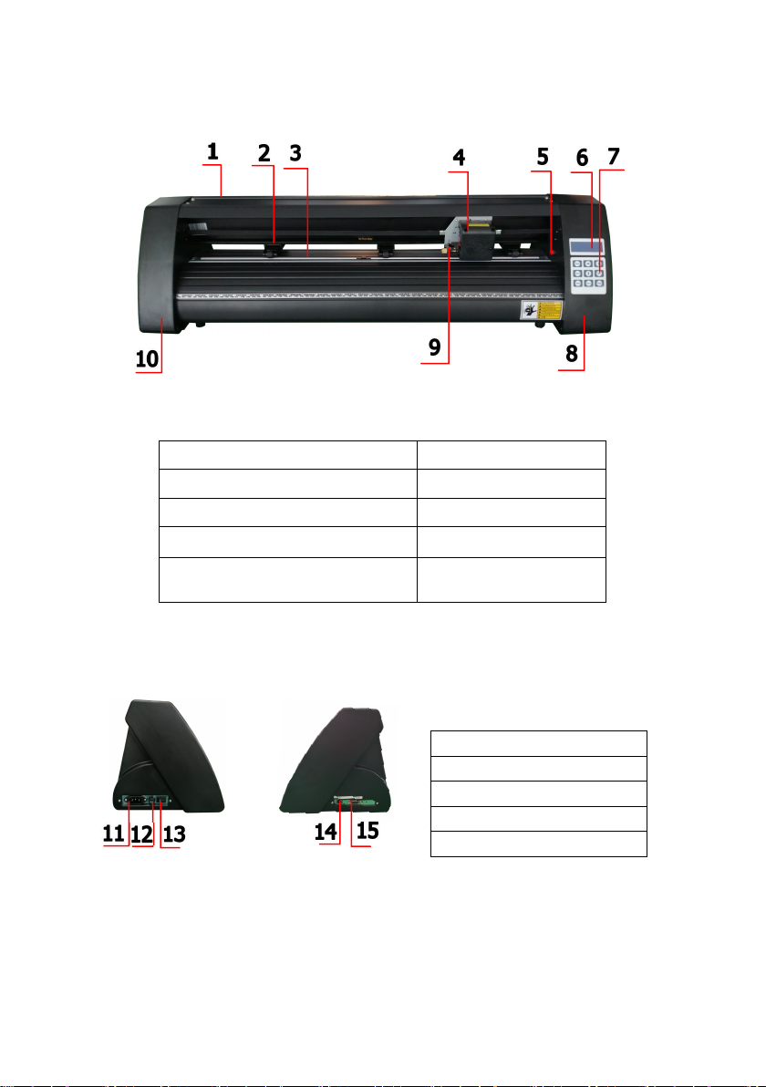
VEVOR KH-375 User manual

1
Contents
Ⅰ.Precautions…………………………………………………............................2
Ⅱ. Introduction for main parts………………............................…....3-6
Ⅲ. Technical parameters………….…..............................................7-8
Ⅳ. Bracket assembly diagram……..…………..............................….9-12
Ⅴ.Blade assembly……...............................................................13-15
Ⅵ.How to use the product…......................................................16-23
Ⅶ.How to connect products to software............................................24
Ⅷ. Software and driver installation…........................................25-30
Ⅸ. Connection of software and machine…...............................31-34
Ⅹ.Troubleshooting..................................................................35-37

2
Ⅰ.Precautions
1. Protective material must be removed before turning on the cutting plotter.
2. Check the label on the back side of the plotter to confirm that the rated
voltage required by the plotter matches the voltage of the power base.
3. Firstly make sure that the power switch is off, then plug the power supply
into grounded power outlet.
4. Please do not touch the power cord with wet hands to avoid electric shock.
5. Please only use the power cord, data cable provided with this product, or
manufacturer-approved replacements.
6. Please do not drop metal objects and liquids into the machine to avoid
malfunction.
7. After shutting down, you must wait another 5 seconds to turn on the cutting
plotter again, otherwise it will cause damage to the cutting plotter.
8. In thunderstorms, turn the power switch to OFF and unplug the power cord.
9. Please do not privately change the manufacturer's components.
10. Manufacturer reserves the right to change product specifications without
prior notice.
11. The manufacturer only bears the legal obligations of the product itself sold
to the users, and does not bear other losses caused by the malfunction of
the products.
12. Without our company’s permit, no part of this manual can be copied or
transmitted in any name.
13. Do NOT drag the carriage by hand.
14. If there is an abnormal sound after powering on the machine, please turn off
the power immediately and contact the after-sales department for feedback.

3
Ⅱ. Introduction for main parts
KH Model
Left side Right side
1.Cover for rail guide
2. Pinch roller kit
3. Roller for feeding paper
4. Carriage
5. Reset switch
6. Screen
7. Buttons
8. The right cover
9. Blade clamp
10. The left cover
11.Power connection
12.Fuse holder
13.Power switch
14.USB port
15.COM port

4
KI Model
Left side Right side
1.Cover for rail guide
2. Pinch roller kit
3. Roller for feeding paper
4. Carriage
5. Screen
6. Buttons
7. The right cover
8. Reset switch
9. Blade clamp
10. The left cover
11.Power connection
12.Fuse holder
13.Power switch
14.USB port
15.COM port
1
2
3
4
5
6
7
10
9
8

5
EH Model
Left side Right side
1.Cover for rail guide
2. Pinch roller kit
3. Roller for feeding paper
4. Carriage
5. Reset switch
6. Screen
7. Buttons
8. The right cover
9. Blade clamp
10. The left cover
11.Power connection
12.Fuse holder
13.Power switch
14.USB port
15.COM port
16.U-disk port

6
SK Model
Left side Right side
1.Cover for rail guide
2. Pinch roller kit
3. Roller for feeding paper
4. Carriage
5. Screen
6. Buttons
7. The right cover
8. Reset switch
9. Blade clamp
10. The left cover
11.Power connection
12.Fuse holder
13.Power switch
14.USB port
15.COM port

7
Ⅲ. Technical parameters
Model
Item
375
720
870
1350
Max. feeding width
375mm
720mm
870mm
1350mm
Max. cutting width
285mm
630mm
780mm
1260mm
Cutting thickness
≤1mm
Speed/Pressure
20-1200mm/s 20-1000g
Buffer
1-4M
LCD display
CN/EN
Real-time
Speed adjusting
Support
Interface
COM+USB / COM+USB+U-DISK
Re-cutting function
Support
Re-cutting accuracy
0.127mm
Resolution Ratio
0.0245mm/step
Language format
DMPL/HPGL
Voltage
AC85-264V

8
Accessory box
Item
Quantity
Unit
1
Cutting plotter
1
Set
2
Power supply cable
1
Pc
3
Blade
1
Box
4
Blade holder
1
Pc
5
Pen holder
1
Pc
6
Ball pen core
1
Pc
7
COM connection cable
1
Pc
8
USB cable
1
Pc
9
Spanner
1
Pc
10
USB driver
1
Pc
11
Bracket screws
1
Bag
To protect the machine, use only the accessories in this
accessory box

9
Ⅳ. Bracket assembly diagram
1-1 Iron bracket assembly diagram
1. M6*40 Hex bolts 8pcs

10
1-2 Al bracket assembly diagram

11
1-3 Sheet metal racket assembly diagram

12
1-4 AI bracket assembly diagram
2-1 lnstall the machine on the bracket

13
Ⅴ. Blade assembly
Blades should be replaced every 6 months. Your blade may need
to be replaced more often if you are cutting thicker material such as
fl ock, glitter, or refl ectives.
1Unscrew the cap from
the Blade Carriage.
2Set Brass Ring on Blade
Carriage to the fully down
position.
3Remove the protective
cover from a newblade.
4Insert the blade into the
top of the Blade Carriage.
5Screw the cap back
onto the Blade Carriage.
6Adjust the carriage cap until the
blade is protruding approximately
1/64 of an inch.
7Adjust the Brass Ring until it fi ts
snug against the Cap. This will help
keep the cap in place during operation.

14
1). Assembly the blade into holder, see as below:
(Appearance view) (Exploded view)
2). Loosen the blade adjustment nut and rotate the shank to adjust the
length of the exposed blade tip. Determine the tip length according to
the thickness of the material.
Correct Blade tip is too long Blade tip is too short
3)Press the pressing rod when you want to change blade. Take out
the blade when it is exposed.
Tips:
Do not touch the blade tip by finger,
otherwise, your finger will be injured and the
tip will be blunt.

15
CARRIAGE SLOT
Holds the blade carriage
in place.
LOCKING KNOB
Allows access to the blade/pen carriage slots
for exchanging/replacing carriages.
1Loosen the locking knob
on the carriage arm.
2Place blade carriage
into the carriage arm.
3Tighten the locking
knob on the carriage arm.

16
Ⅵ.How to use the product
SK Model
KI Model
EH Model
KH Model
The main screen of the cutter allows you to set the main
settings of the cutter including the cutting speed and cutting
force options. It also allows you to cut a test pattern or check
the amount of force that is currently set.

17
Reset BUTTON
Resets by stopping the cutter, and setting the origin
of the carriage arm to its right most position.
Offline/Leave/Option BUTTON
Accesses the Offline/Pause mode.
SETUP BUTTON
Accesses the Setup mode.
TEST/Move BUTTON
Will cut a small test shape so that the current force and
speed settings of the cutter can be tested. You can use this
to determine the proper cutting speed and force settings
needed for dierent materials without wasting large amounts
of material from cutting full designs.
ORIGIN BUTTON
Used to test z-axis functionality (by dropping the blade down
if the carriage is functioning properly) or to set a new origin
point when the machine is in its Offline mode
V+ / V- BUTTONS
Adjusts the cutting speed. A cutting speed of 300 mm/s is a
reasonable default speed that can be used for most cuts.
When working with smaller and more detailed images, a
slower speed may be required. When working with larger
and less detailed images, a higher speed can be used to
shorten the operation time.
F+ / F- BUTTONS
Adjusts the cutting force. A cutting force of 100g is a good
general starting place to work from when trying to determine
the force needed for a specific material. All cut able materials
will dier in the amount of force needed so proper testing should
always be made to determine the amount of force to use. The
amount of force used should be enough to fully penetrate the
material to be cut while not enough to cut through the backing
material.

18
KI Model
SK Model
EH Model
KH Model
Offline mode is used to reposition the cutting material and blade so that a
new starting position can be set for the next design. Offline mode can also
be accessed while the cutter is in operation and will pause the current
cutting process. Although changes can be made to the material and blade
positions if Offline /Pause mode is accessed during cutting, making
changes to either setting is not normally recommended.

19
Reset BUTTON
Offline/Leave/Option BUTTON
SETUP BUTTON
TEST/Move BUTTON
ORIGIN BUTTON
V+ / V- BUTTONS
F+ / F- BUTTONS
Resets by stopping the cutter, and setting the origin of the carriage
arm to its right most position.
Ignores any changes that have been made to the
material or blade positions and exits Offline
ine/Pause mode, returning the cutter to the main
screen. Resumes any cutting that was taking place
when Offline ine/Pause mode was entered.
Has no function in this mode.
Accepts any changes that have been made to the material or
blade positions and exits Offline /Pause mode returning the
cutter to the main screen. Resumes any cutting that was taking
place when Offline /Pause mode was entered from the new
blade/material positions.
Accepts any changes that have been made to the material or blade
positions and exits Offline /Pause mode returning the cutter to
the main screen. Resumes any cutting that was taking place when
Offline /Pause mode was entered from the new blade/material
positions.
Reposition the material by moving the feed rollers. After
movements are made you can confirm the changes by pressing
the TEST or ORIGIN buttons or cancel by pressing the
OFFLINE/PAUSE button.
Reposition the blade by moving the carriage arm. After
movements are made you can confirm the changes by pressing
the TEST or ORIGIN buttons or cancel by pressing the
OFFLINE/PAUSE button.

20
Place the roll on top of the
stand rollers.
For heat press vinyl, please fl ip the
roll.
1
Release the pinch rollers
release levers.
2
Feed the vinyl underneath the
pinch rollers (ifworking from a
single sheet instead of a roll, the
vinyl can also be feed from the
front).
3
Adjust the pinch rollers so there is one roller located on each
side of the vinyl (and, on models with 3 or more rollers, one
roller near the center). Avoid lowering a pinch roller to the
gap between the two feed rollers.
4
This manual suits for next models
15
Table of contents
Other VEVOR Cutter manuals

VEVOR
VEVOR CT-174 User manual

VEVOR
VEVOR J1G-ZB-355B User manual

VEVOR
VEVOR 10190010215 User manual

VEVOR
VEVOR RC-16 User manual

VEVOR
VEVOR 8103E-2/17 User manual

VEVOR
VEVOR SL-400 Installation instructions

VEVOR
VEVOR CT-650 User manual

VEVOR
VEVOR AY-420 User manual

VEVOR
VEVOR YT-160AS User manual

VEVOR
VEVOR k110D User manual