INSTALLATION
This air c mpress r is ideal f r m unting under the h d r even inside
y ur vehicle. The c mpact size f this c mpress r requires minimal
space, and il-less design permits m unting in many different areas f
y ur vehicle. Please read and f ll w these Installati n Instructi ns
carefully t av id injury r damage t the c mpress r r y ur vehicle.
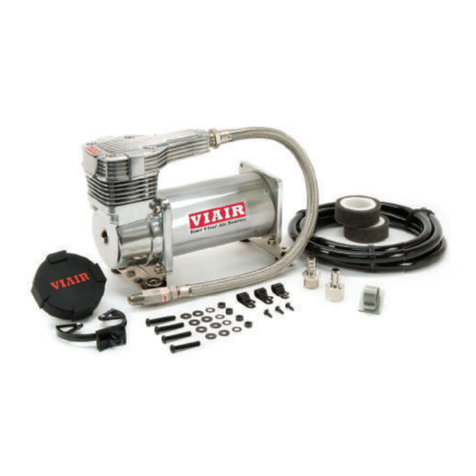
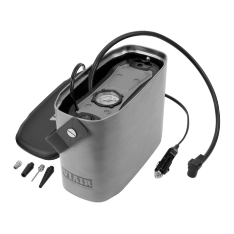
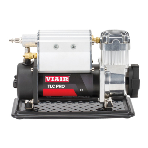
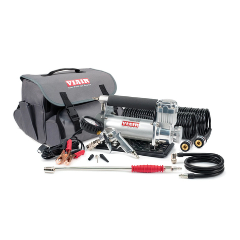
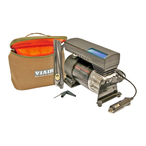
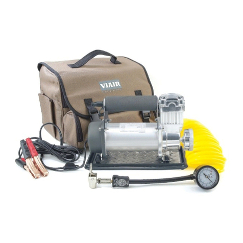
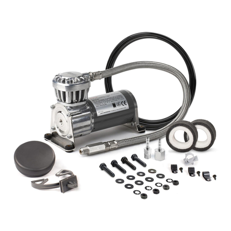
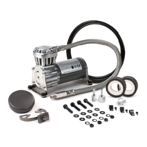
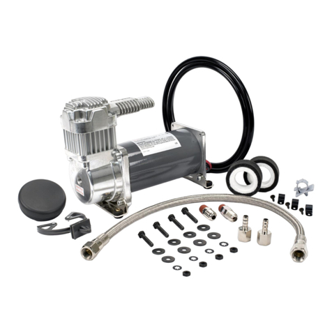
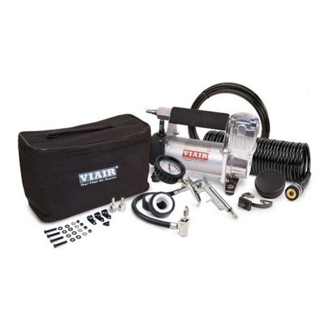
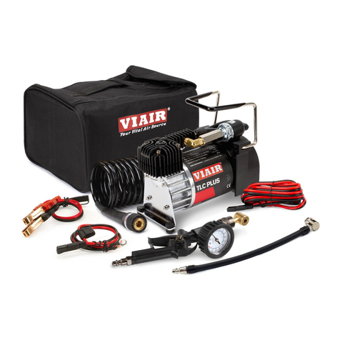
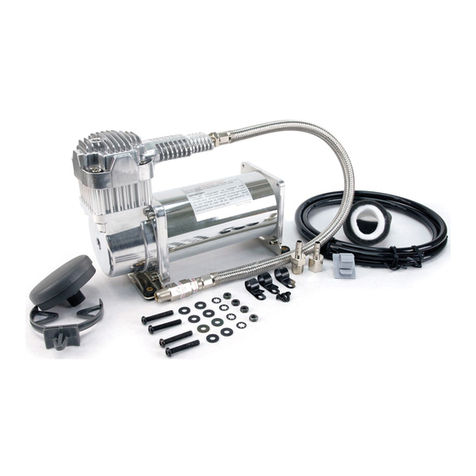
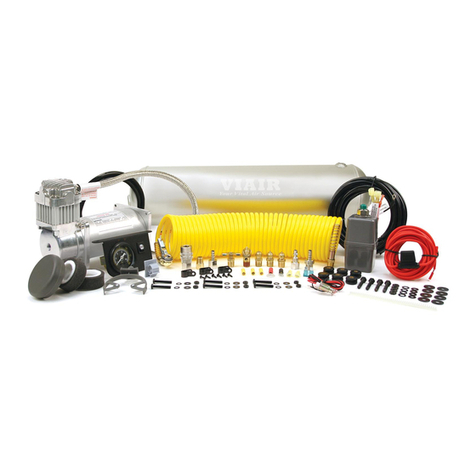
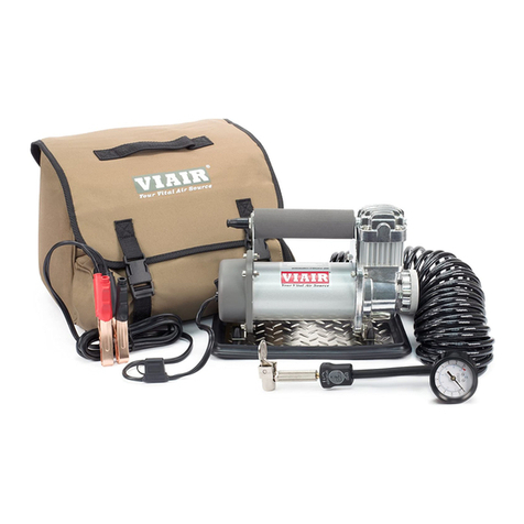
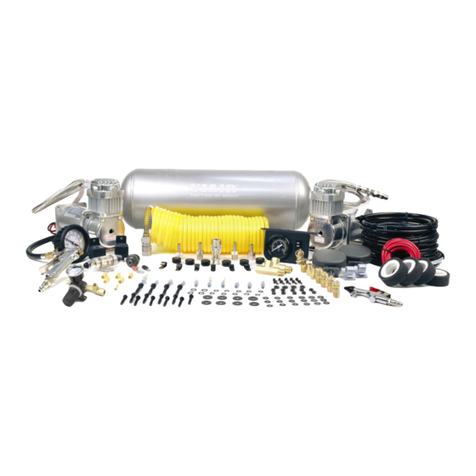
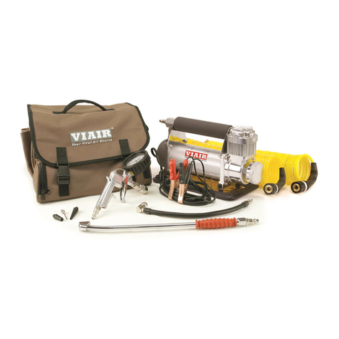
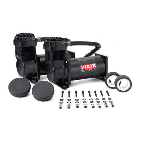
Each f ur air c mpress rs and parts have been
carefully pr duced and packaged. Bef re y u begin
installati n, please familiarize y urself with Installati n
Parts List (Fig. 1) f this manual.
Guidelines f r Selecting M unting L cati n:
The selecti n f pr per m unting l cati n f r y ur air
c mpress r will help ensure a l ng and tr uble free
c mpress r service life. Please pay cl se attenti n t
the f ll wing guidelines:
1. Select a FLAT AND SECURE l cati n where the
c mpress r can be m unted by using the
m unting brackets pr vided.
2. Ch se a l cati n where the 10 ft. p sitive wire
pr vided is l ng en ugh t reach the battery and
where there is an appr priate chassis gr unding
p int t be reached by the 2ft. gr und wire.
3. T maximize air c mpress r perf rmance and
minimize amp draw, l cate c mpress r as CLOSE
TO THE BATTERY as p ssible s that the length f
p sitive lead wire required is at a minimum.
4. Ch se a m unting l cati n that is AS COOL AS
POSSIBLE AND AWAY FROM HEAT SOURCES.
The c ler the ambient temperature (air
temperature surr unding the air c mpress r), the
less chance the c mpress r will verheat.
5. This c mpress r is m isture & splash resistant,
but NOT WATERPROOF. DO NOT MOUNT
COMPRESSOR IN LOCATIONS WHERE THE UNIT
IS LIKELY TO COME IN CONTACT WITH WATER.
6. Select a c mpress r m unting l cati n where air line
can be r uted fr m c mpress r air inlet t rem te
inlet air filter. Make sure Rem te Inlet Air Filter is
l cated in a dry l cati n, away fr m water splashes.
7. Y u will als want t select a c mpress r
m unting l cati n where the leader h se bracket
can be m unted t secure the 1.5 ft. leader h se.
8. If it is necessary t m unt the air c mpress r further
away fr m the battery, such as inside y ur vehicle r
in the bed f y ur pickup, the 10ft. p sitive wire may
n t be l ng en ugh. Use a l nger minimum 8 AWG
p sitive lead wire f r rem te installati n.
9. D n t m unt c mpress r near areas where
flammable liquids are st red.
MOUNTING AND WIRING
1. Disc nnect gr und cable fr m vehicle’s battery.
2. Temp rarily p siti n the air c mpress r in the l cati n where
it will be m unted. R ute the p sitive wire t the p sitive p st
f the battery. Measure and cut p sitive wire t the
appr priate length and use appr priate inline fuse.
3. R ute gr und wire t the negative p st f the battery
r t an appr priate chassis gr unding p int and cut
gr und wire t length as needed.
4. M unt the air c mpress r by using the pair f anti-
vibrati n m unting brackets and f ur sets f
13/64” (5mm) b lts, nuts, washers, and l cking
washers pr vided. Use 13/64” drill bit t drill h les f r
the first set f brackets. M unt this first bracket with
screws, flat washers, l cking washers and nuts
pr vided. (Refer t Fig. 2 f r placement f washers.)
5. Place c mpress r int m unted bracket. Place sec nd set f
bracket under the air c mpress r, make sure that the
c mpress r sits snuggly in between the tw brackets. Mark
ff h les t be drilled using the sec nd set f brackets as
guides. Drill h les, and place c mpress r snugly between
brackets and m unt the sec nd bracket.
6. Refer t Rem te Air Filter Installati n Instructi ns
included in the Rem te Inlet Air Filter Pack f r
installati n f Rem te Inlet Air Filter.
7. This air c mpress r c mes equipped with a 1.5 ft. heavy duty
heat resistant leader h se with _-inch fittings. This leader
h se is designed t pr vide easy access f r air h se
attachment and t pr l ng the life f y ur extensi n h se as
well as minimizing wear t the c mpress r air utlet. D n t
rem ve this leader h se fr m the air c mpress r.
8. Please n te, the leader h se that c mes with y ur
c mpress r may have a built-in inline check valve installed.
D n t rem ve inline check valve fr m leader h se.
9. Select a pr per l cati n t m unt leader h se with h se
bracket pr vided. Av id l cati ns where leader h se
may bec me tangled with wires and ther h ses.
10. T m unt h se bracket, drill h le with 3/16” drill bit
and push self–anch ring h se bracket pin int h le.
R ute leader h se thr ugh h se bracket and secure
h se by pressing bracket clamp int l cked p siti n.
11. T rem ve h se fr m the h se bracket, simply press
d wn n the h se clamp release tab t release
bracket clamp. (Fig. 3)
12. Attach gr und wire t the negative p st f the battery r
chassis gr unding p int. Check t make sure that the air
c mpress r’s ON/OFF switch is in the OFF p siti n.
Attach p sitive wire t p sitive terminal f the battery.
13. Re-check t make sure that all c nnecti ns are made
securely.
