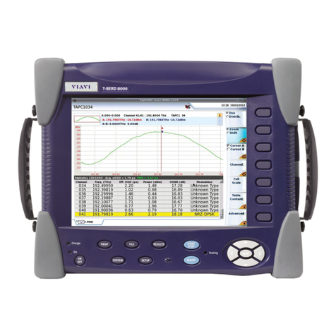
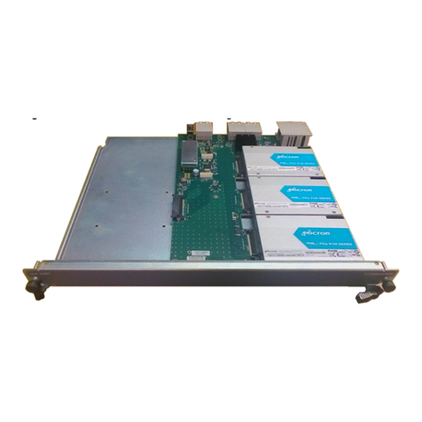
Viavi ODM V2 User manual

ODM Module
Optical Dispersion Measurement
Module
User Manual


User Manual 700MAN901 Rev. 000 v
Notice
Every effort was made to ensure that the information in this document was accurate at
the time of printing. However, information is subject to change without notice, and VIAVI
reserves the right to provide an addendum to this document with information not avail-
able at the time that this document was created.
Copyright
© Copyright 2023 VIAVI, LLC. All rights reserved. No part of this guide may be repro-
duced or transmitted electronically or otherwise without written permission of the
publisher. VIAVI Solutions and the VIAVI logo are trademarks of Viavi Solutions Inc.
(“VIAVI”).
The Bluetooth®word mark and logos are registered trademarks owned by Bluetooth
SIG, Inc. and any use of such marks by VIAVI is under license.
All other trademarks and registered trademarks are the property of their respective
owners.
Copyright release
Reproduction and distribution of this guide is authorized for US Government purposes
only.
Terms and conditions
Specifications, terms, and conditions are subject to change without notice. The provision
of hardware, services, and/or software are subject to VIAVI’s standard terms and condi-
tions, available at www.viavisolutions.com/en/terms-and-conditions.
Open Source Disclaimer - IMPORTANT READ CAREFULLY
The ONA-800 includes third party software licensed under the terms of separate open
source software licenses. By using this software you agree to comply with the terms and
conditions of the applicable open source software licenses. Software originated by VIAVI
is not subject to third party licenses. Terms of the VIAVI Software License different from
applicable third party licenses are offered by VIAVI alone

vi User Manual 700MAN901 Rev. 000
Manual
This guide is a product of VIAVI's Technical Information Development Department. This
manual gives you the main information to install, start and use the ODM module.
WEEE Directive Compliance
VIAVI has established processes in compliance with the Waste Electrical and Electronic
Equipment (WEEE) Directive, 2002/96/EC, and the Battery Directive, 2006/66/EC.
This product, and the batteries used to power the product, should not be disposed of as
unsorted municipal waste and should be collected separately and disposed of according
to your national regulations.
In the European Union, all equipment and batteries purchased from VIAVI after 2005-
08-13 can be returned for disposal at the end of its useful life. VIAVI will ensure that all
waste equipment and batteries returned are reused, recycled, or disposed of in an envi-
ronmentally friendly manner, and in compliance with all applicable national and interna-
tional waste legislation.
It is the responsibility of the equipment owner to return equipment and batteries to VIAVI
for appropriate disposal. If the equipment or battery was imported by a reseller whose
name or logo is marked on the equipment or battery, then the owner should return the
equipment or battery directly to the reseller.
Instructions for returning waste equipment and batteries to VIAVI can be found in the
Environmental section of VIAVI’s web site at www.viavisolutions.com. If you have ques-
tions concerning disposal of your equipment or batteries, contact VIAVI’s WEEE
Program Management team.

User Manual 700MAN902 Rev. 000 vii
Contents
About This Guide
xi
Purpose and scope . . . . . . . . . . . . . . . . . . . . . . . . . . . . . . . . . . . . . . . . . . . . . xii
Assumptions . . . . . . . . . . . . . . . . . . . . . . . . . . . . . . . . . . . . . . . . . . . . . . . . . . . xii
Technical assistance . . . . . . . . . . . . . . . . . . . . . . . . . . . . . . . . . . . . . . . . . . . . xii
Recycling Information . . . . . . . . . . . . . . . . . . . . . . . . . . . . . . . . . . . . . . . . . . xii
Conventions . . . . . . . . . . . . . . . . . . . . . . . . . . . . . . . . . . . . . . . . . . . . . . . . . . . xii
Chapter 1 Getting started
1
Precautions related to optical connections . . . . . . . . . . . . . . . . . . . . . . . 2
Connecting fiber optic cable . . . . . . . . . . . . . . . . . . . . . . . . . . . . . . . . . . . . . 2
Inspecting and cleaning connector end faces. . . . . . . . . . . . . . . . . . . . 2
Connecting Fiber optic cable to test port . . . . . . . . . . . . . . . . . . . . . . . 4
Optical connectors and interchangeable adapters . . . . . . . . . . . . . . . . 4
Adapter types . . . . . . . . . . . . . . . . . . . . . . . . . . . . . . . . . . . . . . . . . . . . . . . . 4
Switching adapter type . . . . . . . . . . . . . . . . . . . . . . . . . . . . . . . . . . . . . . . 5
Cleaning the universal connector. . . . . . . . . . . . . . . . . . . . . . . . . . . . . . . 5
Chapter 2 Polarization Mode Dispersion Measurement
7
Recommended equipment. . . . . . . . . . . . . . . . . . . . . . . . . . . . . . . . . . . . . . . 8
PMD Activation and self calibration. . . . . . . . . . . . . . . . . . . . . . . . . . . . . . 8
Configuring the PMD test . . . . . . . . . . . . . . . . . . . . . . . . . . . . . . . . . . . . . . . 8

Contents
viii User Manual 700MAN902 Rev. 000
Acquisition parameters . . . . . . . . . . . . . . . . . . . . . . . . . . . . . . . . . . . . . . . 9
Analysis parameters . . . . . . . . . . . . . . . . . . . . . . . . . . . . . . . . . . . . . . . . . . 11
Alarms parameters . . . . . . . . . . . . . . . . . . . . . . . . . . . . . . . . . . . . . . . . . . . 13
Link Description parameters. . . . . . . . . . . . . . . . . . . . . . . . . . . . . . . . . . .14
Report parameters . . . . . . . . . . . . . . . . . . . . . . . . . . . . . . . . . . . . . . . . . . .16
Saving configuration in a file. . . . . . . . . . . . . . . . . . . . . . . . . . . . . . . . . .19
Loading a configuration file . . . . . . . . . . . . . . . . . . . . . . . . . . . . . . . . . . 20
Performing a PMD measurement . . . . . . . . . . . . . . . . . . . . . . . . . . . . . . . 20
Remote operator . . . . . . . . . . . . . . . . . . . . . . . . . . . . . . . . . . . . . . . . . . . . 20
Local operator . . . . . . . . . . . . . . . . . . . . . . . . . . . . . . . . . . . . . . . . . . . . . . .21
Display of results . . . . . . . . . . . . . . . . . . . . . . . . . . . . . . . . . . . . . . . . . . . . . . 22
Spectrum/FFT key . . . . . . . . . . . . . . . . . . . . . . . . . . . . . . . . . . . . . . . . . . . 22
Display of PMD results . . . . . . . . . . . . . . . . . . . . . . . . . . . . . . . . . . . . . . 22
Cursors . . . . . . . . . . . . . . . . . . . . . . . . . . . . . . . . . . . . . . . . . . . . . . . . . . 23
Zoom access . . . . . . . . . . . . . . . . . . . . . . . . . . . . . . . . . . . . . . . . . . . . . 23
Statistics results . . . . . . . . . . . . . . . . . . . . . . . . . . . . . . . . . . . . . . . . . . . . . . . 24
Table of results. . . . . . . . . . . . . . . . . . . . . . . . . . . . . . . . . . . . . . . . . . . . . . 24
Graphics display. . . . . . . . . . . . . . . . . . . . . . . . . . . . . . . . . . . . . . . . . . . . . 25
Information messages . . . . . . . . . . . . . . . . . . . . . . . . . . . . . . . . . . . . . . . 26
Saving the trace and generating a report . . . . . . . . . . . . . . . . . . . . . . . .27
Saving results and creating a report from results page . . . . . . . . . .27
Opening the report. . . . . . . . . . . . . . . . . . . . . . . . . . . . . . . . . . . . . . . . . . 30
Recalling PMD files . . . . . . . . . . . . . . . . . . . . . . . . . . . . . . . . . . . . . . . . . . . 31
Chapter 3 Attenuation profile
33
Recommended equipment . . . . . . . . . . . . . . . . . . . . . . . . . . . . . . . . . . . . . 34
AP Activation and self calibration. . . . . . . . . . . . . . . . . . . . . . . . . . . . . . . 34
Configuring the AP test . . . . . . . . . . . . . . . . . . . . . . . . . . . . . . . . . . . . . . . . 34
Reference. . . . . . . . . . . . . . . . . . . . . . . . . . . . . . . . . . . . . . . . . . . . . . . . . . . 35
Acquisition parameters . . . . . . . . . . . . . . . . . . . . . . . . . . . . . . . . . . . . . . 35
Analysis parameters . . . . . . . . . . . . . . . . . . . . . . . . . . . . . . . . . . . . . . . . . 36
Display parameters . . . . . . . . . . . . . . . . . . . . . . . . . . . . . . . . . . . . . . . . . . .37

Contents
User Manual 700MAN902 Rev. 000 ix
Saving configuration in a file . . . . . . . . . . . . . . . . . . . . . . . . . . . . . . . . . 38
Loading a configuration file . . . . . . . . . . . . . . . . . . . . . . . . . . . . . . . . . . 39
AP Reference Measurement . . . . . . . . . . . . . . . . . . . . . . . . . . . . . . . . . . . . 40
Performing the reference. . . . . . . . . . . . . . . . . . . . . . . . . . . . . . . . . . . . . 40
Saving a reference measurement. . . . . . . . . . . . . . . . . . . . . . . . . . . . . . 43
Loading existing reference . . . . . . . . . . . . . . . . . . . . . . . . . . . . . . . . . . . 43
Performing a AP measurement . . . . . . . . . . . . . . . . . . . . . . . . . . . . . . . . . 44
Display of AP results . . . . . . . . . . . . . . . . . . . . . . . . . . . . . . . . . . . . . . . . . . . 45
Trace display . . . . . . . . . . . . . . . . . . . . . . . . . . . . . . . . . . . . . . . . . . . . . . . . 45
Spectrum/Profile. . . . . . . . . . . . . . . . . . . . . . . . . . . . . . . . . . . . . . . . . . 45
Cursor and Zoom functions. . . . . . . . . . . . . . . . . . . . . . . . . . . . . . . . . 46
Results table . . . . . . . . . . . . . . . . . . . . . . . . . . . . . . . . . . . . . . . . . . . . . . . . 47
Saving the trace and generating a report. . . . . . . . . . . . . . . . . . . . . . . . 47
Saving results and creating a report. . . . . . . . . . . . . . . . . . . . . . . . . . . 47
Recalling AP files . . . . . . . . . . . . . . . . . . . . . . . . . . . . . . . . . . . . . . . . . . . . 49
Chapter 4 CD measurements using phase shift method
51
CD activation and self calibration . . . . . . . . . . . . . . . . . . . . . . . . . . . . . . . 52
Configuring the CD test . . . . . . . . . . . . . . . . . . . . . . . . . . . . . . . . . . . . . . . . 52
Reference . . . . . . . . . . . . . . . . . . . . . . . . . . . . . . . . . . . . . . . . . . . . . . . . . . . 53
Acquisition parameters. . . . . . . . . . . . . . . . . . . . . . . . . . . . . . . . . . . . . . . 53
Analysis parameters . . . . . . . . . . . . . . . . . . . . . . . . . . . . . . . . . . . . . . . . . 54
Display parameters . . . . . . . . . . . . . . . . . . . . . . . . . . . . . . . . . . . . . . . . . . 55
Alarms parameters. . . . . . . . . . . . . . . . . . . . . . . . . . . . . . . . . . . . . . . . . . . 57
Saving configuration in a file . . . . . . . . . . . . . . . . . . . . . . . . . . . . . . . . . 58
Loading a configuration file . . . . . . . . . . . . . . . . . . . . . . . . . . . . . . . . . . 59
CD Reference measurement . . . . . . . . . . . . . . . . . . . . . . . . . . . . . . . . . . . . 59
Performing the reference. . . . . . . . . . . . . . . . . . . . . . . . . . . . . . . . . . . . . 59
Saving a reference measurement. . . . . . . . . . . . . . . . . . . . . . . . . . . . . . 62
Loading existing reference . . . . . . . . . . . . . . . . . . . . . . . . . . . . . . . . . . . 62
Performing a CD Measurement . . . . . . . . . . . . . . . . . . . . . . . . . . . . . . . . . 63
Performing a CD measurement through amplifiers . . . . . . . . . . . . . . 64

Contents
x User Manual 700MAN902 Rev. 000
Display of CD results . . . . . . . . . . . . . . . . . . . . . . . . . . . . . . . . . . . . . . . . . . . 65
General display . . . . . . . . . . . . . . . . . . . . . . . . . . . . . . . . . . . . . . . . . . . . . 65
Functions available . . . . . . . . . . . . . . . . . . . . . . . . . . . . . . . . . . . . . . . . . . 66
Delay / Dispersion / Slope . . . . . . . . . . . . . . . . . . . . . . . . . . . . . . . . . 66
Cursor and Zoom functions . . . . . . . . . . . . . . . . . . . . . . . . . . . . . . . . 67
Saving the trace and generating a report . . . . . . . . . . . . . . . . . . . . . . . 67
Saving results and creating a report . . . . . . . . . . . . . . . . . . . . . . . . . . 67
File Signature . . . . . . . . . . . . . . . . . . . . . . . . . . . . . . . . . . . . . . . . . . . . . . . 68
Recalling reference or CD measurement files . . . . . . . . . . . . . . . . . . 68
Chapter 5 Technical specifications and commercial references
69
ODM Modules technical specifications. . . . . . . . . . . . . . . . . . . . . . . . . . 70
ODM Modules references . . . . . . . . . . . . . . . . . . . . . . . . . . . . . . . . . . . . . . .72
Appendix A RoHS Information
73
Declaration of Conformance: China RoHS Material Disclosure . . . . 74
Index
75

User Manual 700MAN902 Rev. 000 xi
About This Guide
The VIAVI ODM module is a compact, single test port, field test solution combining Chro-
matic Dispersion (CD), Polarization Mode Dispersion (PMD) and Attenuation Profile
(AP) measurements in a single module
The topics discussed in this chapter are as follows:
•“Purpose and scope” on page xii
•“Assumptions” on page xii
•“Technical assistance” on page xii
•“Recycling Information” on page xii
•“Conventions” on page xii

About This Guide
Purpose and scope
xii User Manual 700MAN902 Rev. 000
Purpose and scope
The purpose of this guide is to help you successfully use the equipment features and
capabilities. This guide includes task-based instructions that describe how to configure,
use, and troubleshoot the equipment with ODM module.
Assumptions
We are assuming that you have basic computer and mouse/track ball experience and
are familiar with basic telecommunication and fiber optic concepts and terminology.
Technical assistance
If you require technical assistance, call 1-844-GO-VIAVI. For the latest TAC information,
go to http://www.viavisolutions.com/en/services-and-support/support/technical-assis-
tance.
Recycling Information
VIAVI recommends that customers dispose of their instruments and peripherals in an
environmentally sound manner. Potential methods include reuse of parts or whole prod-
ucts and recycling of products components, and/or materials.
Waste Electrical and electronic Equipment (WEEE)
Directive
In the European Union, this label indicates that this product should not be
disposed of with household waste. Il should be deposited at an appropriate
facility to enable recovery and recycling.
Conventions
This guide uses naming conventions and symbols, as described in the following tables.

About This Guide
Conventions
User Manual 700MAN902 Rev. 000 xiii
Table 1 Typographical conventions
Description Example
User interface actions appear in this typeface. On the Status bar, click Start.
Buttons or switches that you press on a unit
appear in this TYPEFACE.
Press the ONswitch
Code and output messages appear in this type-
face.
All results okay
Text you must type exactly as shown appears in
this typeface.
Type: a:\set.exe in the dialog box
Variables appear in this typeface. Type the new hostname.
Book references appear in this typeface. Refer to Newton’s Telecom Dictio-
nary
A vertical bar | means “or”: only one option can
appear in a single command.
platform [a|b|e]
Square brackets [ ] indicate an optional argu-
ment.
login [platform name]
Slanted brackets < > group required arguments. <password>
Table 2 Keyboard and menu conventions
Description Example
A plus sign + indicates simultaneous keystrokes. Press Ctrl+s
A comma indicates consecutive key strokes. Press Alt+f,s
A slanted bracket indicates choosing a submenu
from menu.
On the menu bar, click
Start > Program Files.

About This Guide
Conventions
xiv User Manual 700MAN902 Rev. 000
Table 3 Symbol conventions
Table 4 Safety definitions
This symbol represents a general hazard.
This symbol represents a risk of electrical shock.
NOTE
This symbol represents a Note indicating related information or tip.
This symbol, located on the equipment or its packaging indicates that
the equipment must not be disposed of in a land-fill site or as municipal
waste, and should be disposed of according to your national regula-
tions.
WARNING
Indicates a potentially hazardous situation which, if not avoided, could result
in death or serious injury.
CAUTION
Indicates a potentially hazardous situation which, if not avoided, may result
in minor or moderate injury.

1
User Manual 700MAN902 Rev. 000 1
Chapter 1 Getting started
This chapter describes how to start using the ODM Module installed into the ONA-800.
The topics discussed in this chapter are as follows:
•“Precautions related to optical connections” on page 2
•“Connecting fiber optic cable” on page 2
•“Optical connectors and interchangeable adapters” on page 4

Chapter 1 Getting started
Precautions related to optical connections
2 User Manual 700MAN902 Rev. 000
Precautions related to optical connections
•The normal operating life of an optical connector is usually of the order of a few
hundred matings.
•The proper operation of the instrument and its accuracy are dependent on the
cleanliness of the optical connectors as well as the care taken in its manipulation.
•The optical connectors must therefore be clean and dust-free. If the optical
connection is not being used, protect the connections of the module using the
protective caps.
Connecting fiber optic cable
Inspecting and cleaning connector end faces
•Optical connector contamination is the #1 source of performance degradation
and test equipment repair
•A single particle mated into the core of a fiber can cause significant back reflec-
tion, insertion loss and equipment damage. Visual inspection is the only way to
determine if the fiber connectors are truly clean before mating them.
Follow this simple "INSPECT BEFORE YOU CONNECT" process to ensure fiber end
faces are clean prior to mating connectors.
Always inspect and clean the connector end face of the optical fiber
cable and the test port before mating both together.
VIAVI is not responsible for damage and reduced performance caused
by bad fiber handling and cleaning.

Chapter 1 Getting started
Connecting fiber optic cable
User Manual 700MAN902 Rev. 000 3
Caution
Never connect a PC connector into an APC test port or vice versa. This will result in
damaging the connector end faces.
Figure 1 "Inspect Before You Connect" process
Figure 2 PC/APC bad connection
WARNING
VIAVI declines responsibilities of connector damages if a poor quality con-
nector is used or APC to PC connections made. Test port connector repair
will be charged

Chapter 1 Getting started
Optical connectors and interchangeable adapters
4 User Manual 700MAN902 Rev. 000
Connecting Fiber optic cable to test port
After ensuring proper cleaning of both end connectors, follow the below steps in order
to correctly and safely connect the optical fiber into the test port:
1Carefully align the connector and test port to prevent the fiber end from touching
the outside of the port and scratching the end face.
2Push the connector to firmly place it inside ensuring physical end face contact.
Optical connectors and interchangeable adapters
Fiber Optic modules may come equipped with a universal connector and adapter
selected at time of order.
Adapter types
VIAVI offers 4 different adapters, all compatible with this connector.
Adapter types supplied are: FC, SC, DIN and ST.
NOTE
If your connector features a keying mechanism, ensure that it is correctly fit-
ted into the test port's insert.
NOTE
If your connector features a screw-on sleeve, tighten the connector to firmly
maintain the fiber in place. Do not over tighten as this will damage the fiber
and the test port.
WARNING
Never force the connector ferrule or insert it with an angle into the test port
adapter. Mechanical stress may permanently damage the ceramic sleeve of
the adapter or the end face of the connector. A new adapter purchase only
will get the unit back to operation.

Chapter 1 Getting started
Optical connectors and interchangeable adapters
User Manual 700MAN902 Rev. 000 5
Switching adapter type
In order to switch from an adapter to another, proceed as shown.
Cleaning the universal connector
Remove the adapter in order to access the ferrule and clean it using a cotton swab.
Figure 3 5 different types of adapters may be mounted on the universal connector
FC Adapter (EUFCAD)
DIN Adapter (EUDINAD)
ST Adapter (EUSTAD)
SC Adapter (EUSCAD)
Figure 4 Removing and refitting an adapter
Pull out in the direction of the
arrow in order to release the
adapter from the lug holes
To place an adapter, position
the handle as shown in order
to engage with the the lugs,
push hard and pull the
handle down

Chapter 1 Getting started
Optical connectors and interchangeable adapters
6 User Manual 700MAN902 Rev. 000
Table of contents
Other Viavi Control Unit manuals

Viavi
Viavi OSA-4100 User manual

Viavi
Viavi MTS/T-BERD TB6000A V2 Technical manual

Viavi
Viavi SCU-1800 User manual

Viavi
Viavi mA-3011 User manual

Viavi
Viavi mA-3A01 User manual

Viavi
Viavi COSA-4055 User manual

Viavi
Viavi T-BERD MTS 5800 User manual

Viavi
Viavi mA-3011 User manual

Viavi
Viavi T-BERD/MTS- 2000V2 User manual

Viavi
Viavi MSAM User manual