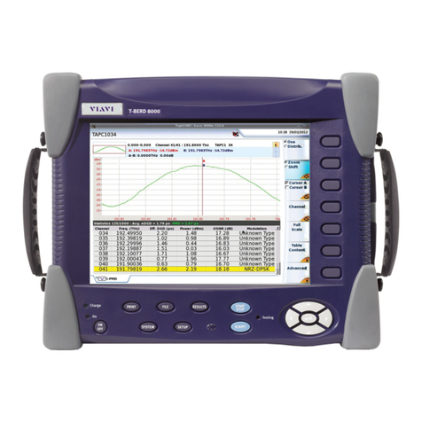
Viavi T-BERD/MTS- 2000V2 User manual

T-BERD/MTS-
2000V2, 4000V2
5800V2
OCC-4056C
User Manual

Please direct all enquiries to your local VIAVI sales
company. The addresses can be found at:
www.viavisolutions.com/en-us/contact-sales-expert
The description ofadditional features ofthe device can befound
at: https://www.viavisolutions.com/en-us/product-category/test-
measurement/network-test-certification
© Copyright 2019 VIAVI Solutions Inc. All rights reserved.
VIAVI and the VIAVI logo are trademarks of VIAVI Solutions
Inc.
All other trademarks and registered trademarks are the
properties of their respective owners.
VIAVI Solutions Deutschland GmbH
Arbachtalstraße 5, 72800 Eningen u. A.
Order no.: BN 2331/98.21
Edition: 2019.04
Previous Edition: --
Note:Changes maybemade to specifications,descriptions and
delivery information.
Printed in Germany

Contents
Introducing the OCC-4056C module ................................. 4
SFP slots ........................................................................ 5
Safety information............................................................... 5
Conventions....................................................................5
Proper usage.................................................................. 6
General laser safety ....................................................... 6
Specific laser safety........................................................7
Optical surfaces..............................................................8
Ventilation....................................................................... 8
Battery operation ............................................................ 8
Start the OCC application................................................... 9
Configuration....................................................................... 9
TestAuto WDM mode.....................................................9
Manual configuration .................................................... 10
Acquisition parameters..................................................11
Analysis parameters.....................................................12
Parameters of display and analysis of the results........14
Link Description............................................................18
File Configuration .........................................................19
Acquisition.........................................................................20
T-BERD/MTS-2000V2, 4000V2, 5800V2 • OCC-4056C • User Manual 2019.04 1
Contents

Trace display functions.................................................20
Result display....................................................................21
Overview.......................................................................21
Using the cursor............................................................23
The Zoom function........................................................23
The Shift function..........................................................24
The measurement function...........................................24
Multiple traces (Overlay)...............................................27
Table display......................................................................29
Overview.......................................................................29
Table contents...............................................................30
Table statistics...............................................................31
Channel sort .................................................................31
Table notes....................................................................32
Result colors.................................................................33
Trace & Table display........................................................34
Drift measurement ............................................................ 34
Reports...............................................................................37
Fast Report...................................................................37
File system report.........................................................38
File management...............................................................39
Storing OSA measurements.........................................39
Recalling OSA files .......................................................39
Recycling information ...................................................... 40
VIAVI Environmental Management Program ...............40
RoHS ............................................................................41
2 T-BERD/MTS-2000V2, 4000V2, 5800V2 • OCC-4056C • User Manual 2019.04

T-BERD/MTS-2000V2, 4000V2, 5800V2 • OCC-4056C • User Manual 2019.04
3
Optical Spectrum
Measurement
This chapter describes the different stages in carrying out a spectrum
analysis of an optical CWDM signal.
The topics discussed in this chapter are as follows:
–“Introducing the OCC-4056C module” on page 4
–“Safety information” on page 5
–“Configuration” on page 9
–“Acquisition” on page 20
–“Result display” on page 21
–“Table display” on page 29
–“Trace & Table display” on page 34
–“Drift measurement” on page 34
–“File management” on page 39
–“Recycling information” on page 40
NOTE
This manual is an addition to the 5800 Base Unit user manual. For all
questions not covered in this manual –particularly concerning safety
–please refer to the Base Unit user manual.

4
T-BERD/MTS-2000V2, 4000V2, 5800V2 • OCC-4056C • User Manual 2019.04
Chapter 1 Optical Spectrum Measurement
Introducing the OCC-4056C module
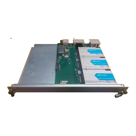
Fig. 1 OCC-4056C module
The OCC-4056C is VIAVI’s new generation of DWDM analyzer
modules. It scans the full C-band wavelength range between 1528 and
1568 nm for commissioning, upgrade, and trouble shooting of DWDM
networks. The OCC-4056C offers the functionality and speed of an
optical spectrum analyzer in a handheld form at a fraction of the price
of an OSA. The measurement result is displayed in a graphical (trace)
and numerical (table) format providing detailed information of the power
level and the wavelength of DWDM channels.
BN 2331/12
NOTE
The OCC-4056C is compatible with
T-BERD/MTS Version 2 only!

T-BERD/MTS-2000V2, 4000V2, 5800V2 • OCC-4056C • User Manual 2019.04
5
Chapter 1 Optical Spectrum Measurement
Safety information
SFP slots The OCC-4056C offers 2 integrated SFP slots for mounting up to2SFP
transceivermodules or tunable lasers(tobe orderedseparately).These
SFP+ modules can be used as a DWDM stimulus to check DWDM
networks together with the DWDM analyzer.
In order to activate the these SFP+ Slots, the tunable SFP SW-option
2331/94.01 needs to be installed. An activated transceiver module
connected to the SFP+ slot emits optical radiation at the output “TX”. The
input “RX” of the transceiver module has no function. The optical laser
radiation is indicated by LEDs assigned to the SFP slots. The SFP
modules are hot pluggable and can be changed during operation of the
OCC-4056C.
Safety information
Conventions Thisguideusesnamingconventionsandsymbols,asdescribedinthe
following tables.
Symbol conventions
This symbol represents a general hazard.
This symbol represents a risk of electrical shock.
This symbol represents dangerous laser radiation.

6
T-BERD/MTS-2000V2, 4000V2, 5800V2 • OCC-4056C • User Manual 2019.04
Chapter 1 Optical Spectrum Measurement
Safety information
Safety definitions
Properusage Thisinstrumentisintendedformeasurementsonopticalfiberdevices
and systems.
Please make sure the device is not operated outside the permitted
ambient conditions.
Observe the specified measurement range.
Always make sure that the device is in proper working order before
switching it on.
General
laser safety
WARNING
Dangerous laser radiation
Always be aware of the hazard level of the device to be
connected.
Connect all optical fibers before switching on the radiation source.
Switch off the laser source before disconnecting the optical fibers.
Never look directly into the output of a laser source or into an
optical fiber connected to it.
Always cover unusedports.
Heed the normal precautions for working with laser radiation and
consider local regulations.
WARNING
Indicates a potentially hazardous situation which, if not avoided, could
result in death or serious injury.
CAUTION
Indicates a potentially hazardous situation which, if not avoided, may
result in minor or moderate injury.

T-BERD/MTS-2000V2, 4000V2, 5800V2 • OCC-4056C • User Manual 2019.04
7
Chapter 1 Optical Spectrum Measurement
Safety information
WARNING
Specific
laser safety
CAUTION
To find out the appropriate laser classification, associated wavelengths
and optical power levels, see:
–the label on the SFP module
–the “Specifications” chapter in the operating manual of the SFP
In accordance with the laser classification, read and follow the
instructions given in the laser safety warnings below.
Laser classification of the SFP transceiver in the SFP slot
SFP laser classification
Use only class 1 laser products in the SFP slots.
However, theuser is freeto use any other SFP transceiver compatible
with the SFP Multi Source Agreement (MSA).
In this case you must observe the laser classification of the
inserted SFP transceiver and its safety instructions!
Invisible laser radiation
Laser radiation can cause irreparable damage to eyes and skin.
Follow the laser safety regulations that apply in your area.
Take note of the laser classification of the individual test module.
Take note of the laser classification or hazard level of the device
under test.
Make sure that you protect yourself and others from exposure to
laser radiation.
Never look into optical outputs of devices or into the plug end
surfaces (free ends) of optical fibers.
Always cover disconnected optical plugs or disconnected optical
cable connectors with protective caps.
Always switch off the instrument and disconnect it from any fiber
optic cables before inspecting or cleaning the optical cable
connectors.
Make sure that the fiber optic cables are disconnected from all
sources of radiation before they are cleaned or inspected and
ensure that they are not reconnected until cleaning or inspection
has been completed.

8
T-BERD/MTS-2000V2, 4000V2, 5800V2 • OCC-4056C • User Manual 2019.04
Chapter 1 Optical Spectrum Measurement
Safety information
CAUTION
WARNING
Safety instructions for class 1 laser products
Safety instructions for class 1M laser products
Optical
surfaces
Dust and fingerprints can damage optical surfaces, particularly when
such surfaces are pressed together. To protect the instrument and
cables, every cable should be cleaned before it is connected to the
instrument. The optical connectors on the instrument should also be
cleaned regularly.
–Before cleaning the optical surfaces please pay attention to the
notes on safe handling of fiber optical cables and optical
connectors.
–Toclean the optical connectors, remove the test adapters, dab the
end surfaces of the plug pins with cleaning tape and blow out the
test adapter using compressed air.
–Always fit protective caps to optical connectors that are not in use.
Ventilation Pleasereferto theBaseUnitusermanualforfurther information.
Battery
operation
Please refer to the Base Unit user manual for further information.
Invisible laser radiation
Class 1 laser products are defined as safe in normal operation under
reasonably foreseeable conditions.
Although the laser radiation from a class 1 laser product will not
harm eyes or skin, follow the general laser safety instructions (see
General laser safety instructions) to ensure maximum safety
when working with laser sources.
Invisible laser radiation
Viewing the laser output of a class 1M laser product with certain
optical instruments (for example eye loupes, magnifiers,
microscopes) within a distance of 100 mm may pose an eye hazard.
Do not expose eyes to the beam within a distance of 100 mm.
Do not view the laser output with optical instruments.
Follow the general laser safety instructions.

T-BERD/MTS-2000V2, 4000V2, 5800V2 • OCC-4056C • User Manual 2019.04
9
Chapter 1 Optical Spectrum Measurement
Start the OCC application
The fiber to be tested is connected to the optical connector.
1. Select the Fiber Optics button.
2. Select on the Home button.
3. Tostart the OCC application, select the OCC button.
Configuration
After connecting the fiber to be tested to the optical connector, you must
select the OCC module (see the Base Unit manual).
To configure the Base Unit in preparation for a OCC test on a fiber,
press the SETUP button. Two configuration procedures are available:
–“Test Auto WDM mode”
In this case the parameters are selected automatically.
–“Manual configuration”
In this case you may define your own configuration.
Test Auto WDM
mode
1. Press the Test Auto WDM softkey.
Following configuration will automatically beset.
Parameter
Setting
Acquisition settings
Sweep
Single
Measurements settings
Channel detection
Permanent
Signal threshold
Auto
Splitter compensation
No
Results screen settings
Grid
default = last value used
Alarms
No
Table notes
No
Unit
nm

10
T-BERD/MTS-2000V2, 4000V2, 5800V2 • OCC-4056C • User Manual 2019.04
Chapter 1 Optical Spectrum Measurement
Configuration
In case of any parameter setting the Test Auto WDM softkey appears.
Fig. 2 Test Auto WDM softkey (1)
Manual
configuration
Instead of selecting the Test Auto WDM mode the configuration
parameters can be set manually.
Theparametertobemodifiedmustbeselectedbymeansofthedirection
keys . The possible options then appear on the screen: make your
choice using the direction keys and . Alternatively, change the
parameters via the touchscreen.
The various parameters proposed are defined below.
Fig. 3 Configuration for optical spectrum measurements.
(The softkeys available depend on the grid settings.)

Chapter 1 Optical Spectrum Measurement
Configuration
T-BERD/MTS-2000V2, 4000V2, 5800V2 • OCC-4056C • User Manual 2019.04
11
Acquisition
parameters
Sweep
Continuous There will be a measurement with refreshment of
the trace and real time display of results.
Single There will be one single measurement and the
display of its results.
Statistics In this mode, the number of samples concerned by
statistics must be entered (next parameter).
Drift For measuring power and wavelength over time.
The number of sweeps and the latency between
the sweeps need to be set.
Number of sweeps
–In Statistics mode: between 2 and 1000
–In Drift mode: between 2 and 10000
Wait Period
The Wait Period parameter allows to enter a wait period prior to the
measurement start (in Statistics and Drift mode only).
s
NOTE
For Drift measurements a Grid needs to be defined and the Channel
Detection parameter is set to Grid.
Up to ...
Increments of ...
1 minute
5 seconds
10 minutes
1 minute
60 minutes
5 minutes
24 hours
1 hour

Chapter 1 Optical Spectrum Measurement
Configuration
12
T-BERD/MTS-2000V2, 4000V2, 5800V2 • OCC-4056C • User Manual 2019.04
Analysis
parameters
Fig. 4 Analysis parameters
Channel
Detection
1
Grid The grid serves as a detection reference: it must
therefore be ITU CWDM or Manual. The choice of
grid takes priority over the choice
Channel detection. For example, it is not possible to
choose Channel detection = Grid, if the option
selected for the grid is «None» or «Conventional».
Permanent Automatic detection of the channel on each
acquisition. In this mode the channels are always
detected without making a referencemeasurement.
1. Attention: All modification of these parameters has immediate repercussions on the trace and entails the loss of
the measurement statistics.
NOTE
Those parameters are only linked to the current active fiber.

Chapter 1 Optical Spectrum Measurement
Configuration
T-BERD/MTS-2000V2, 4000V2, 5800V2 • OCC-4056C • User Manual 2019.04
13
Signalthreshold1 Thresholdfordetectionofchannels(see"Channeldetectionthreshold"
on page 26).
Auto –The threshold is determined automatically.
–Toset to Auto: set threshold to -55 dBm.
Manual –Editable from -54.9 to +10 dBm.
–Tomodify values: use direction keys or Edit
Number.
Splitter
compensation
When the measurement is accessed by a splitter, it is possible to
compensate for the loss introduced by this element and to display the
value measured before or after it.
Go to the Splitter compensation line to display a sub-menu proposing
the following options:
Value1 Yes: activation of compensation and choice of its value
using the keys and : or the numeric keypad : from
1 to 30 dB (by increments of 1) or 1 to 99%(by
increments of0.1%).
Unit Choice of compensation in dB or as a percentage of
the value measured.
For example, with a 10 dB splitter, the results will be
augmented by 10 dB. The trace will be offset upwards
by 10 dB. A channel measured at -30 dBm will be
displayed -20 dBm.
NOTE
At the end of an acquisition in permanent mode, it is possible to
create a grid on the basis of the channels detected. To do this, press
the softkey Adopt Grid in the SETUP menu.
NOTE
Modification of the parameters Channel selection and Signal
threshold will only modify the results if the WDM module present is
the one that was used for the acquisition.

Chapter 1 Optical Spectrum Measurement
Configuration
14
T-BERD/MTS-2000V2, 4000V2, 5800V2 • OCC-4056C • User Manual 2019.04
Parameters of
display and
analysis of the
results
Fig. 5 Display parameters
Grid 1. Go to the Grid line to access the Grid sub-menu.
2. Select the Type line to see the different choices and modify them if
required.
Five possible types of grid are proposed with different corresponding
values, some of which are fixed or non-applicable, others editable.
The type Conventional and the option None do not give access to the
parameters of the Grid sub-menu; the others give access to certain
options, as shown in the table of the figure.
NOTE
Those parameters are valid for all traces present on the screen.

Chapter 1 Optical Spectrum Measurement
Configuration
T-BERD/MTS-2000V2, 4000V2, 5800V2 • OCC-4056C • User Manual 2019.04
15
None
Conventional
ITU CWDM
Manual
Grid name
–
–
Editable
Editable
ITU standard
–
–
G.692
N/A
First ITU channel
(with display in
THz)
–
–
Editable, from 196.10 to
191.20THz, by increments of 50
THz
N/A
Channel spacing
–
–
50GHz
N/A
Number of
channels
–
–
Editable, from 1 to 99 by
increments of 1
Editable from
1 to 256
Define channels
–
–
Sub-menu accessible to display the
wavelengths of each channel, name the band,
and name each channel.
Alarms WhenChannelSelectionispositionedonGrid,it ispossibletoactivate
an alarm system. This system is based on a system of thresholds. Any
measurement results that exceed these thresholds are displayed in red
in the table, and the icon appears at the top right of the screen. If all
the results are within the thresholds (no result is in red), the icon
becomes .
To activate the alarm system, go to the Alarms line and select
Active.
NOTE
The maximum real number of channels for ITU grids depends on the
value selected for the first channel and the spacing between the
channels.
NOTE
It is possible to display the grid with the View Grid softkey. A table
appears showing the channel number, the name of the channel, the
reference wavelength and the alarm thresholds for delta frequency,
minimum power and maximum power.

Chapter 1 Optical Spectrum Measurement
Configuration
16
T-BERD/MTS-2000V2, 4000V2, 5800V2 • OCC-4056C • User Manual 2019.04
Fig. 6 Alarm parameters
Thresholds canthen beset (usingthe direction keysor numerickeypad),
to global level or to the level of each channel:
Global alarms
Number of channels Yes/No
Delta channel power1
Composite power2
“No” or threshold modifiable from
0.1 to 60 dB (for “No” set threshold to Min)
“No” or threshold modifiable from -59.9 dBm
to +20 dBm (for “No” set power to Min)
1. Max. acceptable variation between max. power and min. power on allchannels
2. Maximum composite power
Channel alarms
Max channel offset1
Min channel power2
Max channel power3
Yes/No
Yes/No
Yes/No
Channel Number From «001» to the max. number of
channels.
Channel Value Display of the wavelength of the channel
number selected
Delta Offset4
P Min5
P Max6
From 0 to 10 nm
From -55 dBm to P Max
From P Min to +10 dBm
1. Wavelength drift. Selection of the alarm on the basis of the value of DeltaOffset
2. The values are then defined in PMin
3. The values are then defined in PMax
4. Delta of frequency
5. Minimum power
6. Maximum power

Chapter 1 Optical Spectrum Measurement
Configuration
T-BERD/MTS-2000V2, 4000V2, 5800V2 • OCC-4056C • User Manual 2019.04
17
NotesTable Herethedisplaycanbeconfiguredanditcanbespecifiedwhetherornot
it is possible to enter a note for each channel (see "Table notes" on
page 32):
Manual Allows to manually enter a note for each channel in
the results table.
No Notes function isdisabled.
Unit Here the units of the x axis can be selected:
nm Wavelength innm
THz Frequency in THz
Fig. 7 Unit parameters
Table Content Here the table content can be selected.
Fig. 8 Table Content parameters

Chapter 1 Optical Spectrum Measurement
Configuration
18
T-BERD/MTS-2000V2, 4000V2, 5800V2 • OCC-4056C • User Manual 2019.04
Link
Description
Define the parameters in the Link Description menu and add a
comment.
Fig. 9 Link Description parameters
This manual suits for next models
3
Table of contents
Other Viavi Control Unit manuals

Viavi
Viavi ODM V2 User manual

Viavi
Viavi mA-3A01 User manual

Viavi
Viavi MTS/T-BERD TB6000A V1 Technical manual

Viavi
Viavi MTS/T-BERD TB8000e V2 Technical manual

Viavi
Viavi mA-3011 User manual

Viavi
Viavi 8100 V2 Series User manual

Viavi
Viavi COSA-4055 User manual

Viavi
Viavi SPA06MA-O R005 User manual

Viavi
Viavi OSA-4100 User manual

Viavi
Viavi T-BERD MTS 5800 User manual