6 — © 2018 Viavi Solutions (23 Feb 2018)
How to install the SFPs
This product uses hot-swappable SFPs, but you should
disconnect any cables before changing the SFP modules.
Caution: Wear a grounding strap when handling SFPs
to avoid damaging them or other components. Avoid
exposure to laser radiation from optical components by
keeping the dust plugs installed until you are ready to
install the cables.
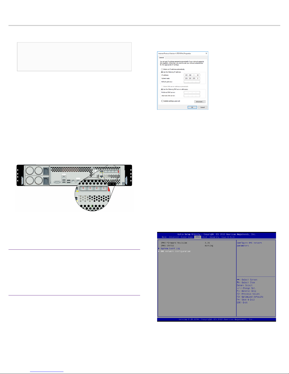
There are numbers etched into the back plate of each Gen3
capture card along the top (Figure 4). These etched numbers
represent the port number assignments from top to bottom.
For example, port 1 is at the top and port 4 at the bottom. This
helps you determine the port number that any SFP is plugged
into. If you need to connect the probe to a monitoring interface
(TAP or SPAN/mirror) different from that shipped with the unit,
simply obtain the necessary SFP for your application and insert
the desired interface.
♦The Gen3 capture card allows for mixing any 1 Gb and
10 Gb transceivers (SFP and SFP+ respectively).
♦Your transceivers can be inserted into any open port
and in any order.
♦You can hot-swap the connected transceivers at
any time, but it is recommended you then re-launch
Observer Analyzer so that the new speeds can be
identified.
How to set the IP address
Set the IP address of the hardware appliance while you still
have physical access to it, such as immediately after it is racked
and cabled. Setting the IP address ensures the hardware
appliance has a visible and permanent network presence.
Prerequisite(s):
♦A running Observer Platform hardware appliance.
♦A KVM switch or keyboard, monitor, and mouse are
connected. The user input devices or KVM switch are
only temporarily needed to set the IP address, so you
can disconnect them after the IP address is set.
♦The IP, subnet, and gateway or router addresses are
available and known to you.
1. Log in to the Windows operating system using the
Administrator account and its default password admin.
You can change the Administrator account password after
logging in. See the Windows documentation if necessary.
2. In Windows, choose Start > Control Panel > Network and
Sharing Center > Change adapter settings.
3. Right-click OnBoard LAN 2 and choose Properties.
OnBoard LAN 2 is the 10/100/1000 port on the right when
viewing the back of the system. OnBoard LAN 1 is the
Ethernet port on the left and is disabled by default.
4. Select Internet Protocol Version 4 (TCP/IPv4), and click
Properties.
5. Set the IP address, subnet mask, router or gateway, and
DNS server for your environment and click OK.
6. Click OK again to close the Properties dialog for that
network connection.
Starting now, all of your interaction with the hardware
appliance can now be done remotely by connecting to the
appliance using other Observer Platform products or Windows
Remote Desktop depending on what you want to accomplish.
Configuring the LOM or IPMI port
Your appliance comes with an on-board LOM or IPMI port that
provides you a dedicated management channel for device
maintenance. It allows you to monitor, start, stop, and manage
your appliance remotely regardless of whether the appliance is
powered on.
If you want to use Lights Out Management features, you
must first configure the IP address for the IPMI port from the
BIOS. Then, you should change the administrator password to
something different than the default.
1. Connect an Ethernet cable from your router or switch to the
IPMI or LOM port.
2. When starting your appliance, press Delete during POST to
enter the BIOS setup.
3. In the BIOS, choose IPMI > BMC network configuration.
4. Set Update IPMI LAN configuration to Yes.
5. Set Configuration Address source to Static.
6. Configure the Station IP address, Subnet mask, and
Router address.
These values must be valid and usable on your network!