Victaulic VE106 Groove-N-Go Manual

TM-VE106/107OPERATING AND MAINTENANCE INSTRUCTIONS MANUAL
VE106 and VE107 Groove-N-Go
PIPE/TUBING ROLL GROOVING TOOLS
WARNING
WARNING
Failure to follow instructions and warnings could result in serious
personal injury, property damage, and/or product damage.
• Before operating or servicing any roll grooving tools, read all
instructions in this manual and all warning labels on the tool.
• Wear safety glasses, hardhat, foot protection, and hearing
protection while working around this tool.
• Save this operating and maintenance manual in a place
accessible to all operators of the tool.
If you need additional copies of any literature, or if you have questions concerning the safe
and proper operation of this tool, contact Victaulic, P.O. Box 31, Easton, PA 18044-0031,
Phone: 1-800-PICK VIC, E-Mail: pickvic@victaulic.com.
Original Instructions
TM-VE106/107
REV_D


TABLE OF CONTENTS
Hazard Identification ................. 4
Operator Safety Instructions ............ 4
Introduction ....................... 6
Receiving the Tool ....................6
Container Contents ...................6
Power Requirements ................. 7
Power Drive Requirements..............7
Extension Cord Requirements ...........7
Tool Nomenclature................... 8
Tool Dimensions and Specifications ...... 9
Tool Setup ........................10
Pre-Operation Checks and Adjustments... 13
Grooving Rolls ......................13
Pipe/Tubing Preparation ..............13
Pipe Lengths Suitable for Grooving .......14
Short Pipe/Tubing Lengths.............14
Long Pipe/Tubing Lengths .............15
Groove Diameter Stop Adjustment........16
Grooving Operation ..................19
Roll Changing ..................... 23
Lower Roll/Main Shaft Removal .........23
Upper Roll Removal..................25
Upper Roll Installation . . . . . . . . . . . . . . . . 26
Lower Roll/Main Shaft Installation .......26
Maintenance ...................... 28
Parts Ordering Information ............ 30
Accessories....................... 30
Troubleshooting.................... 32
Tool Rating and Roll Selection ......... 34
Standard and “ES” Rolls for
Steel Pipe. .........................34
Standard Rolls for Schedules
5S and 10S Stainless Steel Pipe. ........34
Rolls for CTS US Standard –
ASTM Drawn Copper Tubing ...........35
Rolls for Australian Standard –
AS 1432 Copper Tubing...............35
Explanation of Critical Roll
Groove Dimensions ............... 36
Roll Groove Specifications ............ 38
Steel Pipe and All Materials Grooved
with Standard and RX Rolls ............38
Standard-Wall Pipe or Plastic-Coated
Pipe Joined with Style HP-70ES
EndSeal Couplings...................39
CTS US Standard – ASTM B-88
Hard-Drawn Copper Tubing ............40
Australian Standard – AS 1432
Copper Tubing ......................41
EC Declaration of Conformity .......... 42
TM-VE106/107_3
REV_D
TM-VE106/107 / Operating and Maintenance Instructions Manual

HAZARD IDENTIFICATION
Definitions for identifying the various hazard
levels are provided below.
This safety alert symbol indicates
important safety messages. When
you see this symbol, be alert to the
possibility of personal injury.
Carefully read and fully understand the message
that follows.
DANGER
• The use of the word “DANGER” identifies
an immediate hazard with a likelihood
of death or serious personal injury if
instructions, including recommended
precautions, are not followed.
WARNING
• The use of the word “WARNING”
identifies the presence of hazards
or unsafe practices that could result
in death or serious personal injury if
instructions, including recommended
precautions, are not followed.
CAUTION
• The use of the word “CAUTION”
identifies possible hazards or unsafe
practices that could result in personal
injury and product or property damage
if instructions, including recommended
precautions, are not followed.
NOTICE
• The use of the word “NOTICE” identifies
special instructions that are important
but not related to hazards.
OPERATOR SAFETY
INSTRUCTIONS
The VE106/107 is designed for the sole purpose
of roll grooving pipe/tubing. These instructions
must be read and understood by each operator
PRIOR to working with the grooving tools.
These instructions describe safe operation of
the tool, including set up and maintenance.
Each operator must become familiar with the
tool’s operations, applications, and limitations.
Particular care should be given to reading and
understanding the dangers, warnings, and
cautions described throughout these operating
instructions.
Use of these tools requires dexterity and
mechanical skills, as well as sound safety
habits. Although these tools are designed and
manufactured for safe, dependable operation,
it is difficult to anticipate all combinations of
circumstances that could result in an accident.
The following instructions are recommended
for safe operation of these tools. The operator
is cautioned to always practice “safety first”
during each phase of use, including set up and
maintenance. It is the responsibility of the lessee
or user of these tools to ensure that all operators
read this manual and fully understand the
operation of these tools.
Store this manual in a clean, dry area where it
is always readily available. Additional copies of
this manual are available upon request through
Victaulic.
DANGER
1. Avoid using the tool in potentially
dangerous environments. Do not expose
the tool to rain, and do not use the tool in
damp or wet locations. Do not use the tool
on sloped or uneven surfaces. Keep the
work area well lit. Allow sufficient space to
operate the tool properly.
3. Ground the drive motor to protect the
operator from electric shock. Ensure
that the drive motor is connected to an
internally grounded electrical source.
TM-VE106/107_4 REV_D
TM-VE106/107 / Operating and Maintenance Instructions Manual

3. Disconnect electrical power before
servicing the tool. Only authorized
personnel should perform maintenance
on the tool. Always disconnect the power
before servicing or adjusting the tool.
4. Prevent accidental startups. Place the
power switch in the “OFF” position before
connecting the tool to an electrical source.
WARNING
1. Prevent back injury. DO NOT attempt to
lift tool components without the use of
mechanical lifting equipment.
2. Wear proper apparel. Do not wear loose
clothing, jewelry, or anything that can
become entangled in moving parts.
3. Wear protective items when working with
tools. Always wear safety glasses, hardhat,
foot protection, and hearing protection.
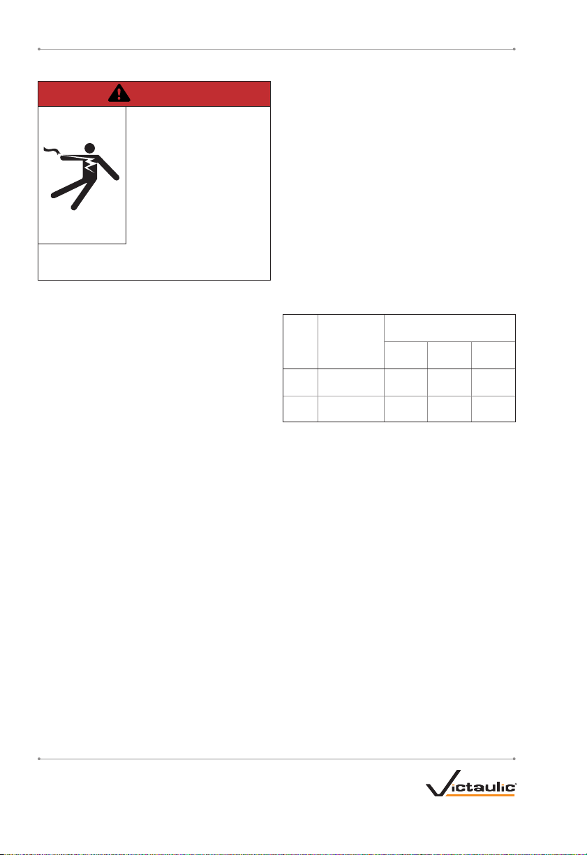
4. Keep hands and tools away from grooving
rolls during the grooving operation.
Grooving rolls can crush or cut fingers and
hands.
5. Do not reach inside pipe ends during tool
operation. Pipe edges can be sharp and
can snag gloves, hands, and shirt sleeves.
6. Operate the tool only with a safety foot
switch. The tool must be operated with
the safety foot switch that is located for
easy operator access. Never reach across
moving parts. If the tool does not contain a
safety foot switch, do not use the tool, and
contact Victaulic.
7. Do not over-reach. Maintain proper footing
and balance at all times. Ensure that the
safety foot switch is easily accessible to the
operator.
CAUTION
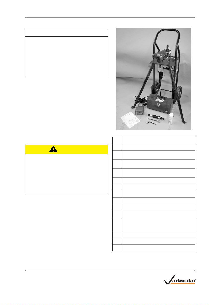
1. This tool is designed ONLY for roll
grooving pipe/tubing sizes, materials, and
wall thicknesses listed in the “Tool Rating
and Roll Selection” section.
2. Inspect the equipment. Before using
the tool, check all moveable parts for any
obstructions. Ensure that all tool components
are installed and adjusted properly.
3. Stay alert. Do not operate the tool if you
are drowsy from medication or fatigue.
4. Keep visitors, trainees, and observers
away from the immediate work area. All
visitors should be kept a safe distance from
the equipment at all times.
5. Keep work areas clean. Keep the work area
around the tool clear of any obstructions
that could limit the movement of the
operator. Clean up any oil or other spills.
6. Secure the work, tool, and accessories.
Ensure that the power drive is secured to
the floor or is otherwise capable of resisting
the full output torque of the power drive
and the weight of the pipe being grooved.
7. Support the work. Support long pipe
lengths with a pipe stand that is secured to
the floor or the ground.
8. Do not force the tool. Do not force the tool
or accessories to perform any functions
beyond the capabilities described in these
instructions. Do not overload the tool.
9. Maintain tool with care. Keep the tool
clean at all times to ensure proper and
safe performance. Follow the instructions
for lubricating tool components.
10. Use only Victaulic replacement parts
and accessories. Use of any other parts
may result in a voided warranty, improper
operation, and hazardous situations. Refer
to the “Parts Ordering Information” and
“Accessories” sections.
11. Do not remove any labels from the tool.
Replace any damaged or worn labels.
TM-VE106/107_5
REV_D
TM-VE106/107 / Operating and Maintenance Instructions Manual

INTRODUCTION
NOTICE
• Drawings and/or pictures in this manual
may be exaggerated for clarity.
• The tool, along with this operating
and maintenance instructions manual,
contains trademarks, copyrights, and/or
patented features that are the exclusive
property of Victaulic.
The Victaulic VE106/VE107 is a manual-feed
tool for roll grooving pipe/tubing to receive
Victaulic grooved pipe/tubing products. The
standard VE106/VE107 tool is supplied with
grooving rolls for 1¼–6 inch/42.4–168.3 mm
carbon steel pipe. Rolls are marked with the
size and part number, and are color-coded to
identify the pipe material. For roll grooving to
other Victaulic specifications and materials, refer
to the “Tool Rating and Roll Selection” section.
Grooving rolls for other specifications, sizes, and
materials must be purchased separately.
CAUTION
• This tool must be used ONLY for roll
grooving pipe/tubing designated in the
“Tool Rating and Roll Selection” section
of this manual.
Failure to follow this instruction could
overload the tool, resulting in reduced tool
life and/or damage to the tool.
RECEIVING THE TOOL
VE106/VE107 Groove-N-Go tools are packed
individually in sturdy containers that are
designed for repeated shipping. Save the original
container for return shipment of rental tools.
Upon receipt of the tool, ensure that all
necessary parts are included. If any parts are
missing, contact Victaulic.
CONTAINER CONTENTS
Qty. Description
1Tool Head Assembly with Cart
3Adjustable Legs (secured in leg storage
tubes of cart)
1Lower Roll/Main Shaft for 4 –6-inch/
114.3 – 168.3-mm Carbon Steel Pipe*
1Lower Roll/Main Shaft for 1¼– 3-inch/
42.4– 88.9-mm Carbon Steel Pipe
1Safety-Foot-Switch Storage Box
1Safety Foot Switch (located inside storage box)
2Operating and Maintenance Manual
1Repair Parts List
1Feed Ratchet
-Spare Shear Pins
-
Depth Gauges for 1¼ – 6-inch/42.4 – 168.3-mm
Schedule 5, Schedule 10, and Schedule 40 Carbon
Steel Pipe
1⁄-inch Hex Key Allen Wrench
1Go/No-Go Pipe Tape
1Can of Dry Graphite Spray
* Installed in the head assembly
NOTE: Optional items, such as roll sets for grooving stainless steel
pipe and copper tubing, may be shipped separately.
TM-VE106/107_6 REV_D
TM-VE106/107 / Operating and Maintenance Instructions Manual

POWER REQUIREMENTS
DANGER
• To reduce the risk of
electric shock, check
the electrical source for
proper grounding.
• Before performing any
maintenance on the
tool, disconnect the
power cord from the
electrical source.
Failure to follow these instructions could
result in death or serious personal injury.
POWER DRIVE REQUIREMENTS
Power must be supplied to the drive motor
through a safety foot switch to ensure safe
operation. Ensure that the power drive is
grounded properly in accordance with Article
250 of the National Electrical Code. Always
refer to the operating manual for the power
drive for additional information.
If an extension cord is required, refer to the
“Extension Cord Requirements” section that
follows for cord sizes.
EXTENSION CORD REQUIREMENTS
When pre-wired outlets are not available and
an extension cord must be used, it is important
to use the proper cord size (i.e. Conductor Size
American Wire Gauge). Cord size selection is
based upon tool rating (amps) and cord length
(feet). Use of a cord size (gauge) thinner than
required will cause significant voltage drop
at the power drive while the tool is operating.
Voltage drops may cause damage to the power
drive and can result in improper tool operation.
NOTE: It is acceptable to use a cord size that is
thicker than required.
The required cord sizes for cord lengths up to
and including 100 ft/31 m are listed in the table
below. Use of extension cords longer than 100
ft/31 m must be avoided.
Model
Power Drive
Rating
volts/amps
Cord Lengths
feet/meters
25
8
50
15
100
31
VE106 110 12 gauge 12 gauge 10 gauge
12
VE107 220 14 gauge 12 gauge 10 gauge
6
TM-VE106/107_7
REV_D
TM-VE106/107 / Operating and Maintenance Instructions Manual

TOOL NOMENCLATURE
NOTICE
• Drawings and/or pictures in this manual
may be exaggerated for clarity.
• The tool, along with this operating
and maintenance instructions manual,
contains trademarks, copyrights, and/or
patented features that are the exclusive
property of Victaulic.
Leg
Storage
Tubes
(3)
Feed
Ratchet
Cart
Adjustable
Legs (3)
Safety Foot Switch
Safety-Foot-Switch
Storage Box
Drive Motor
Lower Roll/
Main Shaft
Upper
Shaft
Overload
Device
Groove
Diameter
Stop
Body Nut
Feed Screw
Drive Socket
Lower
Roll/Main
Shaft
Storage
Groove
Depth
Gauges
1
2
Failure to follow instructions and warnings could result in
serious personal injury, property damage, and/or product
damage.
• Before operating or servicing any pipe preparation tools,
read all instructions in the Operating and Maintenance
Instructions Manual and all labels on the tool.
• Wear safety glasses, hardhat, foot protection, and hearing
protection when working around tools.
0567 Rev. D R031272LAB
If you need additional copies of any literature, or if you have questions concerning the safe and proper
operation of any pipe preparation tools, contact Victaulic, P.O. Box 31, Easton, PA 18044-0031, Phone
1 2
Pipe and groove features, noted below, must be
measured to verify they are within currentVictaulic
specications. Victaulic submittal publications can
be downloaded at www.victaulic.com.
OD= Average Pipe Outside
Diameter
T = Pipe Wall Thickness
A = Distance from Pipe
End to Groove
A B
D
C
F
T
OD
Measure Prior to
Grooving Measure After
Grooving
B = Groove Width
C = Average Diameter
at Base of Groove
D = Groove Depth
F = Pipe-End Flare
7264 Rev. A R207264LBL
Not Shown
TM-VE106/107_8 REV_D
TM-VE106/107 / Operating and Maintenance Instructions Manual

TOOL DIMENSIONS AND SPECIFICATIONS
Tool weight is 140 pounds/64 kilograms.
Tool sound pressure is 95 dB(A), while tool sound power is 97 dB(A). All measurements taken with
a Rems Amigo 2 power drive.
NOTE: Noise measurements are dependent on the power drive, and will vary based on
configuration. Always check the power drive manufacturer’s documentation for details.
Plan View Front View
Side View
22.00 in/
559 mm
39.50 in/
1003 mm
32.25 in/
819 mm
35.00 in/
889 mm
45.00 in/
1143 mm *
40.50 in/
1029 mm
49.00 in/
1245 mm
48.75 in/
1238 mm
* This dimension reects
maximum ram extension.
TM-VE106/107_9
REV_D
TM-VE106/107 / Operating and Maintenance Instructions Manual

TOOL SETUP
WARNING
• DO NOT connect the tool to the electrical
source until instructed otherwise.
Accidental startup of the tool could result in
serious personal injury.
The standard VE106/VE107 Groove-N-Go
tool is intended for field or shop setup. Before
grooving, the adjustable legs must be mounted
onto the tool.
1. Remove components from the packaging, and
ensure that all necessary items are included.
Refer to the “Receiving the Tool” section.
2. Select a location for the tool by taking into
consideration the following factors (refer to the
drawing below for overall dimensions):
a. The required power supply (verify the
voltage of the drive motor as 110 volt or
220 volt)
b. Adequate space to handle pipe/tubing
lengths
c. A firm and level surface for the tool and
pipe stand
d. Adequate clearance around the tool for
adjustment and maintenance
WARNING
• DO NOT lift the tool into the vertical
(upright) position until the two front legs
are installed.
• The tool will be top heavy until the third
leg is installed on the tool. Use caution to
prevent the tool from tipping over.
Failure to follow these instructions could
result in serious personal injury.
3. Ensure that the tool is secure and is in the
horizontal position (lying down) with the handle
of the cart resting against the ground or floor, as
shown above.
4. Remove the legs from the leg storage tubes.
Install the two front legs by inserting them into
the sockets located on the underside of the tool
head table. Ensure that each leg seats properly
in the sockets. Rotate the legs so that each
foot points away from the tool. Using a ½-inch
wrench, tighten each ⁄ – 18 hex bolt to secure
the legs to the tool.
TM-VE106/107_10 REV_D
TM-VE106/107 / Operating and Maintenance Instructions Manual

5. Ensure that the front legs are securely
fastened in the sockets. Lift/tilt the tool into the
vertical (upright) position, as shown above.
6. With the tool in the vertical (upright) position,
install the third leg into the socket adjacent
to the drive motor. Rotate the leg so that the
foot points away from the tool. Using a ½-inch
wrench, tighten the ⁄ – 18 hex bolt to secure
the leg to the tool.
7a. Level the tool from front to back. NOTE:
The top of the tool head table is a good location
to measure “level”, as shown above. If the tool is
not level, proceed with 7a.
7b. Loosen the hex bolts to adjust the legs
in or out, as required, to make the tool level.
Re-tighten all hex bolts after leveling the tool. Do
not extend any of the legs past the hex bolt. If
this cannot be accomplished, move the tool to a
more level surface, and repeat this step until the
tool is level.
DANGER
• To reduce the risk of
electric shock, check
the electrical source for
proper grounding.
• Before performing any
maintenance on the
tool, disconnect the
power cord from the
electrical source.
Failure to follow these instructions could
result in death or serious personal injury.
TM-VE106/107_11
REV_D
TM-VE106/107 / Operating and Maintenance Instructions Manual

8a. Ensure that the drive-motor trigger switch
is depressed in the proper location. The trigger
lock tab must push down on the drive-motor
trigger switch.
8b. Tighten the two trigger-lock switch thumb
screws to maintain this position.
WARNING
• DO NOT operate the drive motor without
a safety foot switch. If the tool does not
contain a safety foot switch, contact
Victaulic.
Operating the tool without a safety foot
switch could result in serious personal
injury.
9a. Remove the safety foot switch from the
storage box.
9b. Plug the cord for the safety foot switch
into a grounded electrical outlet. Refer to the
“Power Requirements” section. If an extension
cord is used, refer to the “Extension Cord
Requirements” section for requirements.
10. Rotate the drive motor switch to the “L”
position to produce counterclockwise rotation
of the lower roll/main shaft and pipe/tubing, as
shown above.
TM-VE106/107_12 REV_D
TM-VE106/107 / Operating and Maintenance Instructions Manual

11. Depress the safety foot switch, check the
rotation of the lower roll/main shaft, and ensure
that the tool is stable. If rotation is clockwise,
rotate the drive-motor switch to the opposite
position. If the tool wobbles, ensure that the legs
are adjusted correctly and that the tool is level
on the floor. If the wobble persists, re-adjust the
legs.
PRE-OPERATION CHECKS AND
ADJUSTMENTS
Every Victaulic roll grooving tool is checked,
adjusted, and tested at the factory prior to
shipment. However, before attempting to operate
the tool, the following checks and adjustments
should be made to ensure proper tool operation.
WARNING
• Before making any tool adjustments,
always disconnect the power cord from
the electrical source.
Accidental startup of the tool could result in
serious personal injury.
GROOVING ROLLS
Ensure that the proper roll set is installed on the
tool for the pipe/tubing size and material that will
be grooved. Roll sets are marked with the pipe/
tubing size and part number, and they are color
coded for the pipe/tubing material. Refer to the
“Tool Rating and Roll Selection” section. If the
proper rolls are not installed on the tool, refer to
the “Roll Changing” section.
PIPE/TUBING PREPARATION
For proper tool operation and production of
grooves that are within Victaulic specifications,
the following guidelines must be followed.
1. Victaulic recommends square-cut pipe/tubing
for use with grooved-end pipe/tubing products.
Square-cut pipe/tubing MUST be used with
FlushSeal®and EndSeal®gaskets. Beveled-end
pipe/tubing may be used for other applications,
provided that the wall thickness is standard
wall (ANSI B36.10) or less and that the bevel
meets ANSI B16.25 (37½º) or ASTM A-53 (30º).
NOTE: Roll grooving beveled-end pipe/tubing
may result in unacceptable flare.
2. Raised internal and external weld beads and
seams must be ground flush with the pipe/
tubing surface 2 inches/50 mm back from the
pipe/tubing ends.
3. All coarse scale, dirt, and other foreign
material must be removed from the interior and
exterior surfaces of the pipe/tubing ends.
CAUTION
• For maximum grooving roll life, remove
foreign material and loose rust from the
interior and exterior surfaces of the pipe/
tubing ends. Rust is an abrasive material
that will wear the surface of grooving
rolls.
Foreign material may interfere with or
damage grooving rolls, resulting in distorted
grooves and grooves that are out of Victaulic
specifications.
TM-VE106/107_13
REV_D
TM-VE106/107 / Operating and Maintenance Instructions Manual

PIPE LENGTHS SUITABLE FOR
GROOVING
The VE106/VE107 Groove-N-Go tool is capable
of grooving short pipe/tubing lengths without the
use of a pipe stand. Refer to the “Short Pipe/
Tubing Lengths” section on this page.
Table 1 shows the minimum and maximum
pipe/tubing lengths that can be grooved without
the use of a pipe stand. Refer to the “Grooving
Operation” section for instructions on how to
groove short pipe/
tubing lengths. For pipe/
tubing longer than what is shown in Table 1,
refer to the “Long Pipe/Tubing Lengths” section.
Pipe/tubing lengths longer than those listed in
Table 1 (and up to 20 feet/6 meters) must be
supported with a pipe stand.
Pipe/tubing lengths from 20 feet/6 meters
up to double-random lengths (approximately
40 feet/12 meters) must be supported with two
pipe stands.
SHORT PIPE/TUBING LENGTHS
WARNING
• Grooving rolls can crush
or cut fingers and hands.
Never groove pipe/tubing
that is shorter than the
recommended lengths listed
in this manual.
NOTICE
• Grooved pipe/tubing nipples, shorter than
those listed in Table 1, are available from
Victaulic.
TABLE 1 - PIPE LENGTHS SUITABLE
FOR GROOVING
Steel and Stainless Steel
Pipe Size
Length
inches/mm
Nominal Pipe
Size inches
or mm
Actual Outside
Diameter
inches/mm Minimum Maximum
1¼ 1.660 836
42.4 205 915
1½ 1.900 836
48.3 205 915
22.375 836
60.3 205 915
2½ 2.875 836
73.0 205 915
33.500 836
88.9 205 915
3½ 4.000 836
101.6 205 915
44.500 836
114. 3 205 915
4½ 5.000 832
127.0 205 815
55.563 832
141.3 205 815
152.4 mm 6.000 10 30
152.4 255 765
66.625 10 28
168.3 255 715
If pipe/tubing is required that is shorter than
the minimum length listed in Table 1, shorten
the next-to-last piece so that the last piece is
as long (or longer) than the minimum length
specified. Refer to the example below.
EXAMPLE: A 20-foot, 4-inch (6.19-m) length
of 6-inch diameter steel pipe is required to
finish a section, and only 20-foot (6.09-m)
lengths are available. Instead of roll grooving
a 20-foot (6.09-m) length of steel pipe and a
4-inch (101.6-mm) length of steel pipe, follow
these steps:
1. Refer to Table 1 and note that for 6-inch
diameter steel pipe, the minimum length that
should be roll grooved is 10 inches (254 mm).
2. Roll groove a 19-foot, 6-inch (5.94-m) length
of steel pipe and a 10-inch (254-mm) length
of steel pipe. Refer to the “Long Pipe/Tubing
Lengths” section.
TM-VE106/107_14 REV_D
TM-VE106/107 / Operating and Maintenance Instructions Manual

LONG PIPE/TUBING LENGTHS
When roll grooving pipe/tubing that exceeds the
maximum length shown in Table 1, a roller-type
pipe stand must be used. The roller-type pipe
stand must be capable of handling the weight of
the pipe/tubing, while allowing the pipe/tubing to
rotate freely.
a. Ensure that the tool is level. Refer to the “Tool
Setup” section for leveling requirements. Set the
pipe stand height to produce a ½to 1° pitch on
the pipe away from the tool (see Figure 1). This
will help promote tracking and reduce pipe end
flare.
b. When flare is excessive, right-to-left tracking
must be kept to a minimum. It may be
necessary to use less than ½º for the tracking
angle (see Figure 2).
c. Installation of couplings on pipe/tubing that
exceeds the maximum allowable flare may
prevent pad-to-pad closure of the housings
and/or may cause damage to the coupling
gasket. Refer to the applicable “Roll Groove
Specifications” table for details.
d. If the tool is properly set up in a level position,
but the back end of the pipe/tubing is higher
than the end being grooved, the pipe/tubing
may not track. As a result, excessive flare may
occur on the pipe/tubing end. Refer to Figures
1 and 2 and the “Tool Setup” section for pipe/
tubing positioning and tool setup requirements.
NOTICE
• Figure 1 shows a typical pipe stand.
• Victaulic offers several pipe stands, such
as the VAPS112 and VAPS224. The
VAPS112 is suitable for ¾ to 12-inch/
26.9 to 323.9-mm sizes. The VAPS224 is
suitable for 2 to 24-inch/60.3 to 610-mm
sizes. Refer to the “Accessories” section.
• For additional information about pipe
stands, refer to the instructions included
with the pipe stand.
e. Position the pipe stand at a distance slightly
beyond half the pipe/tubing length from the tool.
Refer to Figure 1 below.
Tool
Centerline
(Level)
½° to 1°
2 to 4 inches/
50 to 100 mm
Pipe
Centerline
20-foot/6-meter
Length of Pipe
Pipe Angle
Exaggerated for
Clarity
10 ft + 1 ft - 0/
3m + 0.3m - 0
FIGURE 1 – SUPPORT OF PIPE
f. Position the pipe stand approximately 0 to ½º
to the left for the tracking angle. Refer to Figure
2 below.
Tool
Centerline 0° to ½° Max.
0-inches to 2-inches Max./
0-mm to 50-mm Max.
Pipe
Centerline
20-foot/6-meter
Length of Pipe
Pipe Angle
Exaggerated for
Clarity
FIGURE 2 – TRACKING ANGLE
TM-VE106/107_15
REV_D
TM-VE106/107 / Operating and Maintenance Instructions Manual

GROOVE DIAMETER STOP
ADJUSTMENT
The groove diameter stop must be adjusted
for each pipe/tubing size or change in wall
thickness. The groove diameter, which is
identified as the “C” dimension, is listed under
the “Roll Groove Specifications” section. In
addition, a label is affixed to the tool, which lists
the “C” dimensions.
NOTICE
• To perform the following adjustments,
use several short, scrap sections of
pipe/tubing that are the proper material,
diameter, and thickness to be grooved.
Ensure that the scrap sections meet the
length requirements listed in Table 1.
To achieve the proper diameter:
1. Determine the diameter and thickness of the
pipe/tubing to be grooved.
2. Using the feed ratchet (provided), retract (turn
counterclockwise) the feed screw/upper roll until
the pipe/tubing can be slipped completely over
the lower roll.
2a. Back off the groove-diameter stop by
loosening the clamping screw with the supplied
⁄-inch hex key. Turn the groove-diameter stop
counterclockwise several turns.
3. Insert a length of pipe/tubing that is the
correct size and thickness onto the lower roll.
TM-VE106/107_16 REV_D
TM-VE106/107 / Operating and Maintenance Instructions Manual

4. Ensure that the pipe/tubing end contacts the
lower-roll backstop flange completely.
5. Continue supporting the pipe manually.
Using the feed ratchet (provided), advance (turn
clockwise) the feed screw to place the upper roll
into light contact with the pipe/tubing.
6. Locate the groove depth gauges on the tool.
Remove the wing nut from the gauge retainer,
and select the proper groove depth gauge for
the pipe size being grooved.
7. Using the groove depth gauge as a “feeler
gauge” between the groove-diameter stop and
the body nut, adjust the groove-diameter stop
until it contacts the groove depth gauge, as
shown above.
7a. Using the ⁄-inch hex key, tighten the screw
on the groove-diameter stop to maintain the
adjustment made in the previous step.
TM-VE106/107_17
REV_D
TM-VE106/107 / Operating and Maintenance Instructions Manual

8. Replace the groove depth gauge onto the
gauge retainer. Re-install and tighten the wing
nut.
WARNING
Grooving rolls can crush or
cut fingers and hands.
• Before making any tool
adjustments, always
disconnect the power
cord from the electrical
source.
• Loading and unloading pipe/tubing will
place your hands close to the rollers.
Keep hands away from the grooving rolls
during operation.
• Never reach inside the pipe/tubing end
or across the tool or pipe/tubing during
operation.
• Always groove pipe/tubing in a
COUNTERCLOCKWISE direction only.
• Never groove pipe/tubing that is shorter
than the recommended lengths listed in
this manual.
• Never wear loose clothing, jewelry, or
anything that can become entangled in
moving parts.
9. Prepare a trial groove. Refer to the “Grooving
Operation” section.
10. After a trial groove is prepared and the pipe/
tubing is removed from the tool, carefully check
the groove diameter (“C” dimension). Refer
to the “Roll Groove Specifications” section.
The pipe tape, supplied with the tool, is the
best method for checking the “C” dimension.
In addition, a vernier caliper or narrow-
land micrometer can be used to check this
dimension at two locations (90º apart) around
the groove. The average reading must be within
the required groove diameter specification.
CAUTION
• The “C” dimension (groove diameter)
must conform to Victaulic specifications
to ensure proper joint performance.
Failure to follow this instruction could cause
joint failure, resulting in personal injury and/
or property damage.
11. If the groove diameter (“C” dimension) is not
within Victaulic specifications, the diameter stop
must be adjusted.
11a. To DECREASE the groove diameter
(increase groove depth), turn the diameter stop
counterclockwise (when viewed from above the
tool).
11b. To INCREASE the groove diameter
(decrease groove depth), turn the diameter stop
clockwise (when viewed from above the tool).
NOTE: A quarter-turn either way will change the
groove diameter adjustment by approximately
0.013 inch/0.3 mm or 0.051 inch/1.3 mm per full
turn.
12. Prepare another trial groove, and check the
groove diameter (“C” dimension), as described
in step 10. Repeat these steps, as necessary,
until the groove diameter is within specification.
TM-VE106/107_18 REV_D
TM-VE106/107 / Operating and Maintenance Instructions Manual

GROOVING OPERATION
DANGER
• To reduce the risk of
electric shock, check
the electrical source for
proper grounding.
• Before operating
the tool, review the
“Operator Safety
Instructions” section of
this manual.
Failure to follow these instructions could
result in death or serious personal injury.
CAUTION
• This tool must be used ONLY for roll
grooving pipe/tubing designated in the
“Tool Rating and Roll Selection” section
of this manual.
Failure to follow this instruction could
overload the tool, resulting in reduced tool
life and/or damage to the tool.
1. Before grooving, ensure that all instructions in
the previous sections of this manual have been
followed.
2. Plug the safety foot switch into an internally-
grounded electrical source. Ensure that the
safety foot switch and drive motor are grounded.
3. Set the switch on the drive motor to produce
counterclockwise rotation of the lower roll/main
shaft and pipe/tubing when viewed from the
front of the tool. Placing the switch in the “L”
position will produce counterclockwise rotation
of the lower roll/main shaft and pipe/tubing.
WARNING
• The drive motor must be operated with a
safety foot switch. If the drive motor does
not contain a safety foot switch, contact
Victaulic.
Operating the tool without a safety foot
switch could result in serious personal
injury.
4. Ensure that the tool is operational by
depressing the safety-foot-switch pedal. The
lower roll/main shaft must turn counterclockwise
when viewed from the front of the tool. Remove
foot from the safety foot switch.
TM-VE106/107_19
REV_D
TM-VE106/107 / Operating and Maintenance Instructions Manual

5. Using the feed ratchet (provided), rotate the
feed screw counterclockwise to move the upper
roll to the fully up position.
WARNING
Grooving rolls can crush or
cut fingers and hands.
• Before making any tool
adjustments, always
disconnect the power
cord from the electrical
source.
• Loading and unloading pipe/tubing will
place your hands close to the rollers.
Keep hands away from the grooving rolls
during operation.
• Never reach inside the pipe/tubing end
or across the tool or pipe/tubing during
operation.
• Always groove pipe/tubing in a
counterclockwise direction only.
• Never groove pipe/tubing that is shorter
than the recommended lengths listed in
this manual.
• Never wear loose clothing, jewelry, or
anything that can become entangled in
moving parts.
6. Insert a length of pipe/tubing that is the
correct size and thickness onto the lower roll.
7. Ensure that the pipe/tubing end contacts the
lower-roll backstop flange completely.
TM-VE106/107_20 REV_D
TM-VE106/107 / Operating and Maintenance Instructions Manual
Other manuals for VE106 Groove-N-Go
1
This manual suits for next models
1
Table of contents
Other Victaulic Power Tools manuals