VideoLogic Proteus-V User manual

1
PROTEUS-ESSENTIAL
User Manual
Version V2.15
Oct 29, 2021

2
TABLE OF CONTENTS
GENERAL OVERVIEW...................................................................................................................................................................................................................4
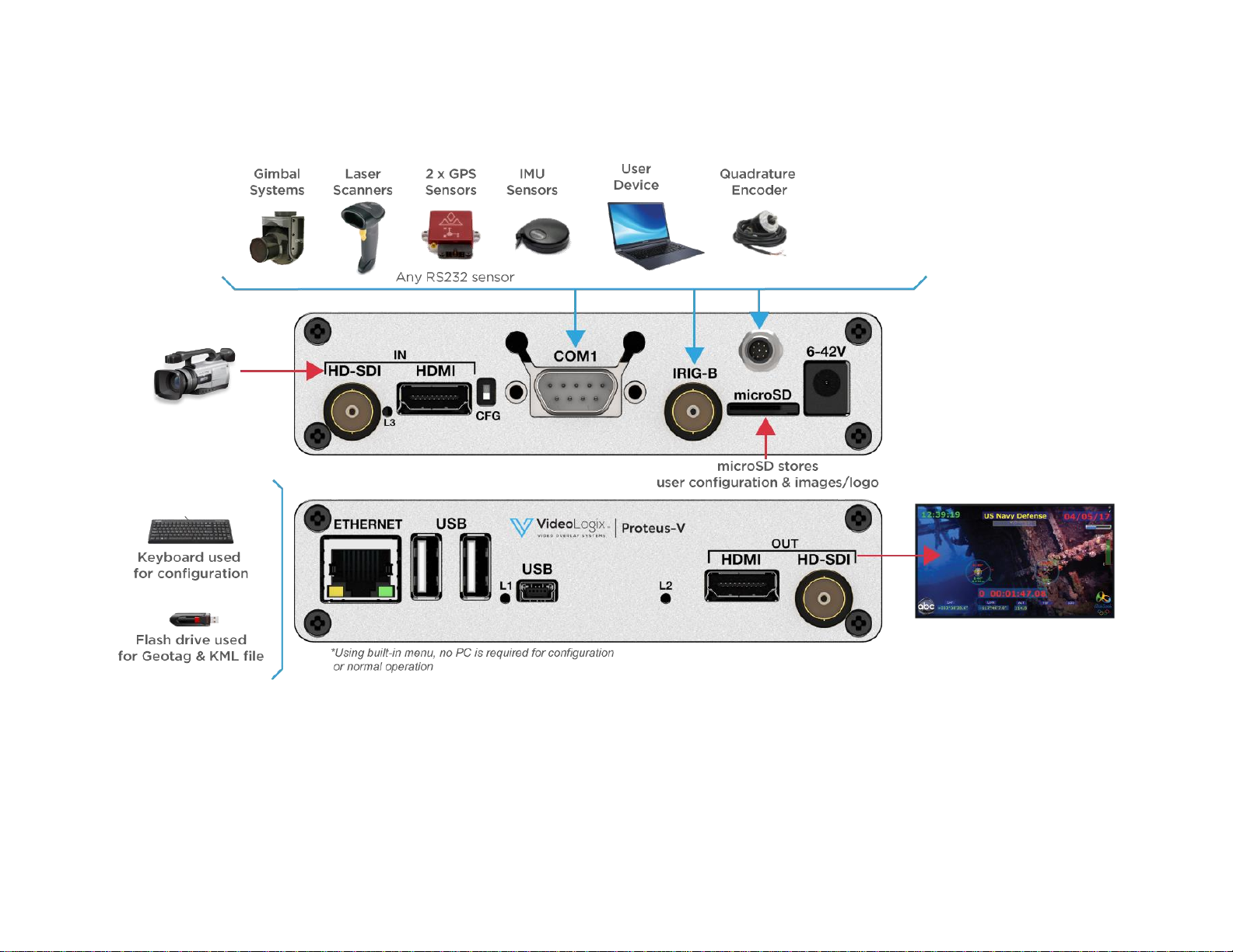
TYPICAL INTERCONNECT DIAGRAM......................................................................................................................................................................................5
GLOSSARY TERMS.........................................................................................................................................................................................................................6
COMMUNICATION .........................................................................................................................................................................................................................6
COM PORTS ......................................................................................................................................................................................................................................6
COM PORTS:BAUD RATES.................................................................................................................................................................................................................6
COM PORTS:DEVICE TYPES ..............................................................................................................................................................................................................6
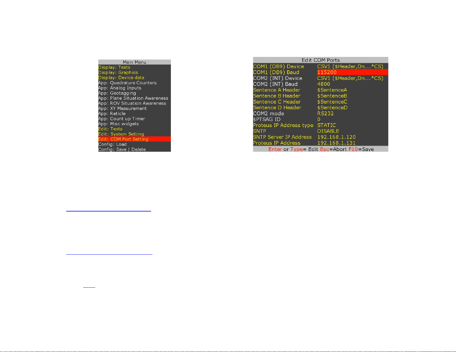
COM PORTS:CONFIGURATION ..........................................................................................................................................................................................................7
COM1...............................................................................................................................................................................................................................................7
COM2...............................................................................................................................................................................................................................................7
COM3: USB DEVICE PORT................................................................................................................................................................................................................7
USB HOST PORTS...............................................................................................................................................................................................................................7
CSV FORMATS ..................................................................................................................................................................................................................................8
ETHERNET PORT ................................................................................................................................................................................................................................9
VIDEO INPUT & OUTPUT............................................................................................................................................................................................................11
VIDEO FRAME RATES.......................................................................................................................................................................................................................12
VIDEO DELAY..................................................................................................................................................................................................................................12
IRIG INPUT......................................................................................................................................................................................................................................12
COMPOSITE INPUT (PIP) ............................................................................................................................................................................................................13
LOAD CONFIGURATION.............................................................................................................................................................................................................14
STORE CONFIGURATION...........................................................................................................................................................................................................14
TEXT, LOGO AND DATA INSERTER........................................................................................................................................................................................15
QUICK TUTORIAL ............................................................................................................................................................................................................................15
DISPLAY TIME,DATE .......................................................................................................................................................................................................................15
DISPLAY TEXT VIA KEYBOARD ........................................................................................................................................................................................................16
DISPLAY IMAGES VIA KEYBOARD....................................................................................................................................................................................................18
DISPLAY GPS DATA..........................................................................................................................................................................................................................19
DISPLAY NMEA 0183 DATA..............................................................................................................................................................................................................21
DISPLAY TEXT VIA RS232...............................................................................................................................................................................................................22
DISPLAY VALUES FROM CSV SENTENCE...........................................................................................................................................................................................22
DISPLAY NMEA 2000 DATA..............................................................................................................................................................................................................26
DISPLAY TILT SENSOR .....................................................................................................................................................................................................................27
REAL TIME ANNOTATION.................................................................................................................................................................................................................28
APPEND MILLISECOND COUNTER TO IRIG,GPS,RTC TIME.................................................................................................................................................................29

3
APPS..................................................................................................................................................................................................................................................30
QUADRATURE OR SIMPLE COUNTERS ...............................................................................................................................................................................................30
ANALOG DATA................................................................................................................................................................................................................................34
XY MEASUREMENT.........................................................................................................................................................................................................................38
RETICLE ..........................................................................................................................................................................................................................................40
PLANE SITUATION AWARENESS ......................................................................................................................................................................................................42
ROV SITUATION AWARENESS..........................................................................................................................................................................................................45
SLIDERS ...........................................................................................................................................................................................................................................48
COMPASS .........................................................................................................................................................................................................................................50
COUNT UP TIMER..............................................................................................................................................................................................................................51
PROTEUS COMMANDS................................................................................................................................................................................................................52
TRANSMIT A COMMAND SCRIPT......................................................................................................................................................................................................52
PROTEUS REGISTERS .................................................................................................................................................................................................................53
SPECIFICATIONS..........................................................................................................................................................................................................................54
MAXIMUM INPUT VOLTAGE.............................................................................................................................................................................................................54
INPUT CONNECTOR ..........................................................................................................................................................................................................................54
ENVIRONMENTAL............................................................................................................................................................................................................................54
WEIGHT &DIMENSION ....................................................................................................................................................................................................................54
FRONT PANEL LED ...........................................................................................................................................................................................................................54
PCB SPECIFICATION ........................................................................................................................................................................................................................55
ENCLOSURE DIMENSION ..................................................................................................................................................................................................................57
APPENDIX A –KEYBOARD COMMANDS ...............................................................................................................................................................................58
KEYBOARD COMMANDS ..................................................................................................................................................................................................................58
KEYBOARD SHORTCUTS ..................................................................................................................................................................................................................58
APPENDIX B –UPDATING FIRMWARE...................................................................................................................................................................................59
APPENDIX C –INSTALL RENESAS FLASH PROGRAMMER .............................................................................................................................................61
APPENDIX D –DISPLAY YOUR IMAGE...................................................................................................................................................................................62
PNG................................................................................................................................................................................................................................................62
JPG .................................................................................................................................................................................................................................................62
STEPS REQUIRED TO ADD AN IMAGE.................................................................................................................................................................................................62
APPENDIX E –CREATE CUSTOM FONTS...............................................................................................................................................................................63
APPENDIX F –TERMINAL BLOCKS.........................................................................................................................................................................................64
APPENDIX H –FORMAT MICROSD..........................................................................................................................................................................................65

4
GENERAL OVERVIEW
Video Overlay is a method by which computer-generated images are superimposed on video. Properly transformed images appear as if
they are an integral part of the scene without impeding the video of the actual environment.
The primary purpose of PROTEUS is to provide the ability to insert text, logos and GPS data.
Numerous apps have been developed to enhance this product. Customers have found them to be useful like the apps available for iPhone.
The existent of these apps should not discourage any customer from considering this product for basic text, logo and GPS data insertion.
PROTEUS supports both HD-SDI, HDMI input & output. It does not need to be connected to a computer for normal operation.
PROTEUS is available in 3 editions and the table below provides a comparison. This User Manual is for PROTEUS ESSENTIAL.
FEATURES
PROTEUS
LITE
ESSENTIAL
PLUS
Insert Texts, Images, Time/Date, GPS data, POS Laser Scanner Code
√
√
√
Insert values from CSV sentences via RS232 & Ethernet
√
√
Insert values from NMEA0183 sensors via RS232
√
√
Insert values from NMEA2000 sensors via CAN
√
√
Numerous APPs + Widgets + Device drivers
√
√
2 x Quadrature inputs
√
√
4 x Analog inputs
√
√
Insert IRIG-B timecode
√
√
Tilt sensor
√
√
30+ Drawing commands via RS232 & Ethernet
√
√
Superimpose composite (NTSC/PAL) video input over HD video input (PIP)
√
√
Geotagging + KML File
√

5
TYPICAL INTERCONNECT DIAGRAM
Diagram below illustrates a few the possible applications.

6
GLOSSARY TERMS
Term
Definition
SCS
Software Communication Specification
CSV
Comma Separated Values
TB
Terminal Block
UM
User Manual
COMMUNICATION
COM PORTS
PROTEUS provides 3 x serial ports for communication with the external devices:
COM PORT
Location
Pin assignments
COM1
RS232:
Rear Panel DB9
2=RX, 3=TX, 5=GND
COM2
RS232:
Internal J54 & J16
J54:
1=RX, 2=GND, 3=TX
COM3
Mini-USB:
Front panel
Standard USB Device
COM PORTS:BAUD RATES
•COM1 & COM2 are fixed for N, 8, 1. However, baud rates can be set to 4800, 9600, 19200, 38400, 57600,115200,230400,460800.
•COM3 is USB Device CDC-ACM class. It allows a USB host (PC) to communicate with the device (Proteus) as a serial device.
There is no baud rate associated with this interface and transfer speed of 1.7 Mbit/s to 4.1Mbit/s can be achieved.
COM PORTS:DEVICE TYPES
COM1-2 ports can be interfaced to various sensors. Table below shows a few examples and their corresponding Device Type setting.
Attach Sensor/Device
Corresponding Device Type setting
Any device transmitting CSV sentences i.e. GPS, IMU, laptop, etc.
CSV1, CSV2, CSV3, CSV4, SSV3, SSV4 (See CSV formats for more detail)
All NMEA-0183 compatible devices i.e. GPS Modem, Sounder, etc.
CSV1, CSV2, CSV3, CSV4, SSV3, SSV4
Serial Terminal program such as PuTTY, Tera Terminal, etc.
CSV1, CSV2, CSV3, CSV4, SSV3, SSV4
Vector NAV IMU
VectorNav
General Dynamic CINEFLEX
CINEFLEX

7
COM PORTS:CONFIGURATION
Press F9 to display the Main Menu. Follow Figure 1-Figure 2 to configure COM ports for desire baud rate & device.
Figure 1
Figure 2
COM1
COM1 (DB9) is configured as DTE (PC) i.e., RX=Pin2, TX=Pin3. Thus, sensors such as GPS can be directly connected to the DB9 without the need for NULL
modem cable. However, when using COM1, a NULL modem cable is required to interface PROTEUS to a PC.
This port can be used to receive remote commands defined in SCS (Software Communication Specification) or connect any RS232 sensor/device that
transmits CSV1, CSV2, CSV3, CSV4, SSV3, SSV4 type data formats.
COM2
COM2 is located internal. Signals TX & RX are provided at J16 connector (Compatible with Garmin GPS 18x LVC) as well as Terminal Block J54.
This port can also be used to receive remote commands defined in SCS (Software Communication Specification) or connect any RS232 sensor/device that
transmits CSV1, CSV2, CSV3, CSV4, SSV3, SSV4 type data formats.
COM3: USB DEVICE PORT
When connected to a PC, it will enumerate as a COM port. This port can be used to receive remote commands defined in SCS (Software Communication
Specification) or CSV1 type formats. This port is also used to upgrade the internal firmware.
USB HOST PORTS
PROTEUS has 2 USB host ports. Typical devices connected to these ports are USB keyboard and USB Flash drive for storing KML data.

8
CSV FORMATS
A CSV is an ASCII sentence composed of a unique header, followed by up to 12 comma separated values and a checksum.
$Header,VAL1,VAL2,VAL3,VAL4,VAL5,VAL6,VAL7,VAL8,VAL9,VAL10,VAL11,VAL12*CS
$
Signifies start of the sentence.
Header
Sentence header. Follow Figure 1-2 to define your unique sentence header.
VALn
Each sentence contains multiple values (VALn) delimited by commas.
*
The asterisk serves as checksum delimiter.
CS
The checksum field contains two ASCII characters which indicate the hexadecimal value of the checksum.
PROTEUS supports 4 different CSV (Comma Separate Values) and 2 different SSV (Space Separate Values) sentences:
Type
Sentence includes
Sentence Structure
Example
Location of parsed VALn
CSV1
$Header, Values…, Checksum
$HEADER,VAL1,VAL2,VAL3,...VALn*CS
$STEVE,45,315,200,100*XX
In sentence A,B,C,D
CSV2
$Header, Values…
$HEADER,VAL2,VAL3,...
$BRIAN,45,315,200,100
In sentence A,B,C,D
CSV3
SSV3
$Values,..
$Values ...
$VAL1,VAL2,VAL3,...
$VAL1 VAL2 VAL3 ...
$45,315,200,100
$45 315 200 100
In sentence A
In sentence A
CSV4
SSV4
Values,…
Values …
VAL1,VAL2,VAL3,..
VAL1 VAL2 VAL3 ..
45,315,200,100
45 315 200 100
In sentence A
In sentence A
Upon reception of a CSV sentence and confirmation of the sentence header (only CSV1), PROTEUS parses the sentence. Parsed values (VAL1 ... VAL12)
are sequentially stored in Registers # 40 through 87. Any widgets linked to these registers will automatically get updated. CSV sentences vary in
length, but each VALn is limited to 40 characters or less.
For more detail on how to use CSV sentences, see Display text via RS232
Display values from csv sentence
The checksum field is the last field in a sentence and follows the checksum delimiter character “*”. The checksum is the 8-bit exclusive OR of all characters
in the sentence, including “,” delimiters, between but not including the “$” and the “*” delimiters. The hexadecimal values of the most significant and least
significant 4 bits of the result is converted to two ASCII characters (0-9, A-F (upper case)) for transmission. The most significant character is transmitted
first. Example: $GPGLL,5057.970,N,00146.110,E,142451,A*27<CR><LF>
In C checksum computation would be written as:
char sentence [] = “GPGLL,5057.970,N,00146.110,E,142451,A”;
int i;
char checksum = 0;
for ( i = 0; i < strlen(sentence); i++)
checksum ^= sentence[i];
Although not recommended, for CSV1 type sentences, checksum computation can be bypassed by replacing CS with XX.

9
ETHERNET PORT
This port can be used to receive remote commands defined in SCS (Software Communication Specification) or any other CSV1 type data formats.
•10M/100M auto sensing network interface
•Networking: Static or DHCP IPv4 addressing
•Subnet Mask: Configurable. Default 255.255.255.0
•Default Gateway: 0.0.0.0
•UDP protocol. Port 9999
To configure Ethernet port, press F9 and select “Edit: COM Port Setting”. Follow Figure 3 - Figure 5 to enable Ethernet port and select IP address.
Following any changes to the Ethernet setting, power must be recycled for the change to take effect.
Figure 3
Figure 4
Figure 5
If DHCP is selected, PROTEUS’s IP address can be viewed by pressing Alt-h (several times) as shown in Figure 6.
Figure 6

10
Free utility Packet Sender can be used to send commands to Proteus. Follow Figure 7 to configure Packet Sender only once.
Figure 7
Follow Figure 8 - Figure 9 to send commands to Proteus. For example, use any text editor i.e., Notepad++ and open file “0-TestCommands.txt” located
in the Script folder. Copy all commands as shown in Figure 8 and paste it into the ASCII Edit box shown in Figure 9 and press Send. The result should
appear on your video screen as shown in Figure 10.
Each command must end with \n. If multiple commands are sent in one packet, end each command with \n as shown below:
“$VL43,46,777*XX\n$VL43,51,Target777*XX\n$VL04,75,7C0000FF*XX\n”
There is no benefit updating parameters any faster than video frame rate i.e., screen refresh rate. For example, when using 1080p @30Hz which
is the fastest frame rate Proteus can handle, keep parameter update rate to 30Hz or less. Typical parameter refresh rate is 10Hz.
Avoid transmitting UDP packets back-to-back. If multiple commands need to be transmitted back-to-back, concatenate them into one payload
as shown above and transmit using one UDP packet.
Figure 8
Figure 9
Figure 10

11
VIDEO INPUT & OUTPUT
PROTEUS provides the following video input & output:
•SDI (HD & SD)
•HDMI (HD & SD)
PROTEUS does not support HDMI video with HDCP. It can only process one video input at a given time. If more than one input is connected at the same
time, PROTEUS selects a video input based on the following priorities:
1. HD-SDI
2. HDMI
PROTEUS does not scale video and the output resolution follows the input. PROTEUS provides simultaneous video outputs.

12
VIDEO FRAME RATES
PROTEUS is compatible with the following video formats:
1080i @
50 / 60 Hz
1080p @
23.98 / 24 / 25/ 29.97/ 30 Hz
1080PsF @
23.98 / 24 Hz
720p @
50 / 59.94 / 60 Hz
NTSC 480i @
60 Hz
PAL 576i @
50 Hz
VIDEO DELAY
All OSD functions are superimposed into the video "on-the-fly." As a result, there is no degradation in video quality and the delay from the video input
to the video output is < 290 nsec.
IRIG INPUT
This interface can be used to input an external unmodulated IRIG-B signal. PROTEUS can decode IRIG-B time & date code. This interface can also be
used to input a composite video NTSC (M, J, 4.43) or PAL (B,D,G,H,I,M,N,CN) for purpose of superimposing it on a HD video as PIP.

13
COMPOSITE INPUT (PIP)
IRIG input can also be used to input a composite video NTSC (M, J, 4.43) or PAL (B,D,G,H,I,M,N,CN) for purpose of superimposing it on a HD video.
To enable PIP follow the pictures below. Composite video (as shown below as colorbar) can be superimposed anywhere on the 1920 x 1080.

14
LOAD CONFIGURATION
PROTEUS supports up to 16 configuration files. When loading a configuration file i.e., ROV.bin, Proteus copies the file into Config.bin. All subsequent
changes will be stored into Config.bin and not the original ROV.bin .
In order to avoid losing your modified configuration by accidental overwrite, highlight ROV.bin and press F10 to save Config.bin into ROV.bin
STORE CONFIGURATION
PROTEUS stores 16 different configurations. Follow figures below to save your configuration.
To back up your current configuration (config.bin), type in a new file name in an empty field or highlight an existing file name (overwrite) and press F10.
To delete an existing configuration file i.e., rov.bin, highlight the file name and press Ctrl + Alt + F10.

15
TEXT, LOGO AND DATA INSERTER
QUICK TUTORIAL
DISPLAY TIME,DATE
1. Press F9 to display main menu
2. Follow Figure 11 - Figure 13 to insert the desired parameter
3. On Figure 13, use ↕arrow keys to select “RTC Time”
4. Press ↲to select “On”
5. RTC time will appear on the screen and flashing.
6. Use shortcuts keys to change the field attributes as described below:
“Font select, field Width, text Justification, text Color, text Background and Ctrl or Alt + ↕↔ text position”
7. Repeat steps 3 through 6 to display “RTC Date”
8. Press F10 to save and exit.
Figure 11
Figure 12
Figure 13

16
DISPLAY TEXT VIA KEYBOARD
Press F9 to display Main Menu. Follow Figure 14 - Figure 15 to type-in or edit pre-exiting texts.
Figure 14
Figure 15
Follow Figure 16 - Figure 17 to display text on video.
Figure 16
Figure 17
While in Figure 17, use ↕arrow keys to select desire text. Press ↲to select “On”. Use shortcuts keys to format the text as described below:
Font select, field Width, text Justification, text Color, text Background and Ctrl or Alt + ↕↔ text position

17

18
DISPLAY IMAGES VIA KEYBOARD
Please review Appendix D –display your image on how to prepare images for use with PROTEUS.
Press F9 to display Main Menu. Follow Figure 18 - Figure 19 to display images.
Figure 18
Figure 19
While in Figure 19,use ↕to select a desire image. Press ↲to select “On”. Use Ctrl or Alt +↕↔ to position the image on screen.

19
DISPLAY GPS DATA
•Two independent GPS modems can be connected to COM1 & COM2 at the same time.
•COM ports are fixed for N, 8, 1. Follow Figure 1 - Figure 2 to configure for desire baud rate
•$GPRMC, $GPGGA, $PTSAG, $GPWPL, $GPGSA, $GPGSV, $GPGGL….
A sample GPS file is provided with your PROTEUS. To load it, press F9, go to “Config: Load” and select “GPS-COM1”or “GPS-COM2”.
11
2
1
3
4
4
1
GPS data
Obtained directly from GPS modem
2
Circular Compass
Controlled via GPS heading
3
Rolling Compass
Controlled via GPS heading
4
Misc. Parameters
Title, Logo. Fully configurable by the user

20
To customize the sample file to meet your needs, follow Figure 20 - Figure 22.
Figure 20
Figure 21
Figure 22
While in Figure 22, use ↕to select desire GPS parameter. Press ↲to select “On”. Use shortcuts keys to format the text as described below:
Font select, field Width, text Justification, text Color, text Background and Ctrl or Alt + ↕↔ text position
Table of contents
Other VideoLogic Video Card manuals
Popular Video Card manuals by other brands

KFA2
KFA2 GeForce Series user manual

Asus
Asus Splendid HD Quick installation guide

Diamond Multimedia
Diamond Multimedia Viper X700 Specification sheet

Matrox
Matrox Millennium G400 user guide

Diamond Multimedia
Diamond Multimedia ATI Radeon 3450PE512 Specification sheet

Gigabyte
Gigabyte GV-N62-512L user manual