Vielight NeuroPro User manual

NeuroPro
USER GUIDE


15
Safety Precautions
Capacity: 10000 mAh
Battery type: Li-polymer
Input: Micro USB & Type C, DC 5V / 2A
Output: USB A: DC 5V / 2A (x2)
Dimensions: 145 x 68 x 14 mm
Weight: 221 g
Power indicator: Yes
Compliance: CE, ROHS, FCC, MSDS
Do not open or puncture the power bank.
Keep the power bank away from water or any other form of moisture.
Avoid exposing the power bank to direct sunlight or high heat.
Do not cover the power bank while it is charging.
Do not power other devices with the power bank while the device is charging.
If the power bank changes shape or becomes excessively hot, stop using it IMMEDIATELY. Do
not use it anymore.
Keep the power bank away from children and animals.

CONTENTS
Components and connecting them together 1, 2
Getting started and positioning 3
Positioning and using Neuro Pro 3, 4
Operating the Neuro Pro 5
Summary of GUI capabilities 6
GUI software structure 7
Glossary of terms for GUI 8
Care and cleaning 9
Power setting vs output power 10
Safety advice: Near-infrared light source 10
Troubleshooting tips 11
Symbols and compliance 12
Technical support 12
EMC information 13
Using the Vielight power bank 14
Limited three-year warranty 16
Disclaimer 16

1
KEY COMPONENTS
NeuroPro
USER GUIDE
Headset
Module A
Nasal applicator
Power adapter 5V 5A with AC input cable
Power adapter 5V 2A for charging smartphone
Smartphone charging cable
USB-A to DC power cable adapter
(connects to optional power bank)
Controller
GUI* via smartphone
Application
Devices
Controlling
Devices
Ancillary Devices
1
2
1
3
3
6
7
8
9
4
5
* GUI - Graphical User Interface
See page 3
CONNECTING
THE DEVICES &
GETTING START-
ED

2
NeuroPro
2
6
45
7
8
9
Bluetooth
link
We recommend users who feel mentally healthy to limit
their use of the device to the default time of 20 minutes,
once every other day.
Because individual sensitivity to photobiomodulation can
themselves and adjust the frequency of use accordingly.
Based on research on light dose response, too little dose

3
POSITIONING THE HEADSET MODULES IN DEFAULT POSITIONS
Position the front
module at midpoint
between eye level
and the apex.
Apex Apex Position the two
side rear
modules at the
midpoint
between the ear
and the apex.
Position the
middle rear
module about 3
to 4 inches (75 to
100 mm) from the
apex.
Eye level Mid-ear
level
R
R
Push or pull
the extender
to suit head
size.
Adjust the Headset for Better Fit
or lengthened by sliding the left and right extender as
shown in the picture.
ADJUSTING THE SIDE PADS AND LIGHT DIODES
Adjustable
angle
Steel bands
Adjust the Steel Band Angle for Better Diode
Contact
Adjust the angle of the steel band to maximize diode
contact with the scalp.
The device can be used the following ways:
by powering the controller via the power adapter .
by powering the device via a power bank (optional). See pages 17 &18.
with or without the smartphone interface. See pages 5, 6, 7 and the GUI
Screenshots guide.
Before starting: 7
8
5
6
CONNECTING THE DEVICES & GETTING STARTED

4
USING THE NASAL APPLICATOR
Press to widen
clip opening
Rib
Sleeve
Lens
If the applicator does not stay on
the nose, use the blue silicone
sleeve. The sleeve has a smooth
side and a ribbed side. Use the
ribbed side for a stronger grip.
POSITIONING THE MODULE A
the extender
C
D
Position the LED module [C] aligned
with the middle of the ear.
Adjust the supports [A] and [B] by
sliding them along the steel band for
The length of the band can be
shortened or lengthened by pushing or
pulling the metal band in or out of the
A
B
NeuroPro
6
5
7
8

5
OPERATING THE NEURO PRO
5
The Neuro Pro is supplied with a GUI smartphone.
The Neuro Pro hardware and the GUI can function independently of each other.
The Neuro Pro controller is pre-programmed with the “Alpha (10 Hz)” setting, and will run
the applicators accordingly when the START button is pressed. The data for Alpha can be
viewed and edited from the GUI.
The GUI for Neuro Pro is pre-installed in the smartphone and is paired with your device.
The serial numbers of the controller and smartphone are identical. Record this number for
your reference.
To use the GUI, switch on the smartphone and look for the Vielight icon.
Activate the app and start using the options available to you.
On the START page, two options are presented.
1. Continue by connecting to the Neuro Pro controller.
2. Continue without connecting to the Neuro Pro controller.
Refer to page 6 for the features available for the 2 options.
Refer to document, Neuro Pro GUI - Screenshots for more details.
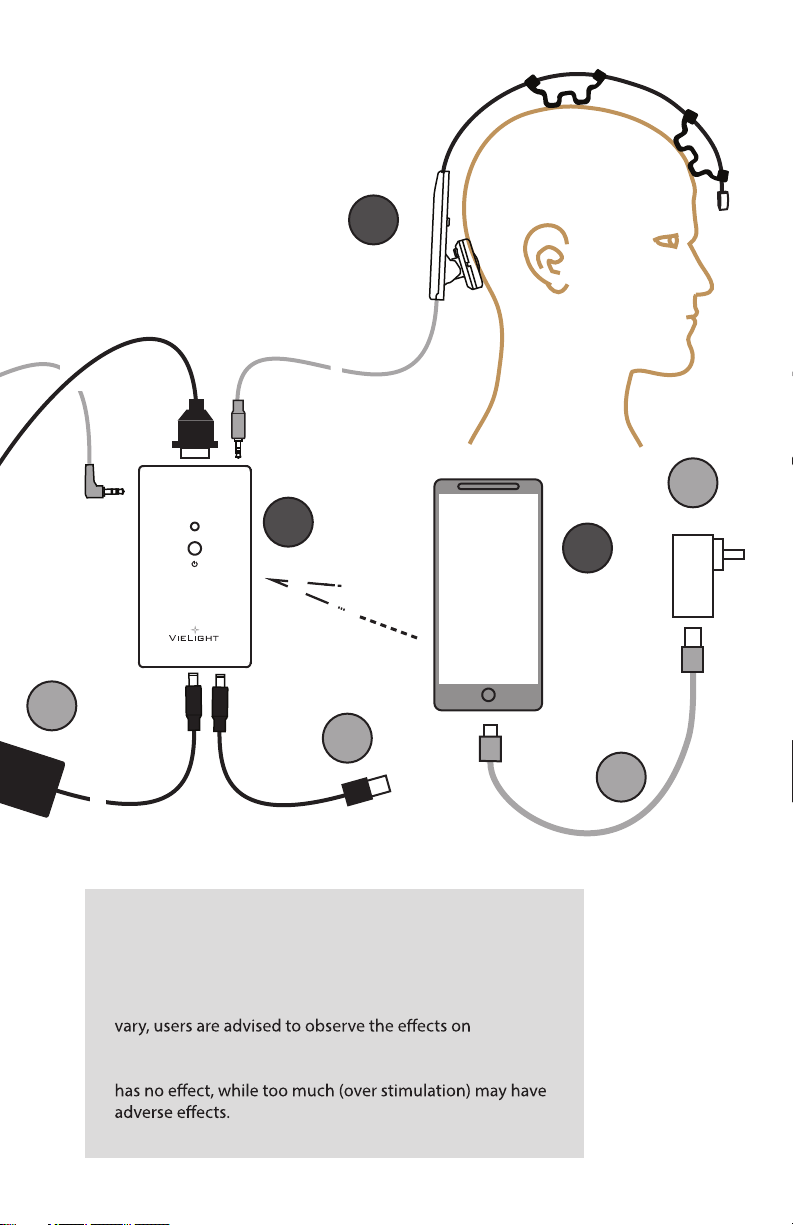
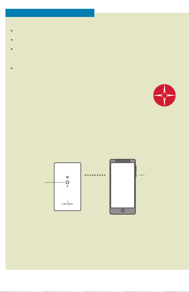
NeuroPro
Bluetooth
link
Controller
Start
button
ON
button
GUI Smartphone

SUMMARY OF GUI CAPABILITIES
6
When the GUI is linked with the Neuro Pro hardware, it has the following supporting
capabilities:
1. Making a run with last used data from the library.
2. Making a run by using the default pre-set data in the hardware.
3. Making a run from data stored in the library.
4. Showing real time run data, including time status, output parameters, phase status, and
group run status.
5. Stopping or pausing a run.
6. Locking the frequency or the power output value when a run is in sweep mode.
7. Select a data set as the default run data in the hardware.
8. Allowing a run to be made with the start button on the Neuro Pro controller. The real time
data will be automatically displayed when the GUI is in the start or library page.
9. Creating a link with the controller when it is running will not interfere with the run.
10. Extracting the run data stored in the Neuro Pro hardware for viewing.
11. Performing a self-test to check if the Neuro Pro hardware is operating within design limits.
12. Creating, editing, and viewing run data settings and records.
13. Storing run settings in the library. The maximum number of settings is 50.
14. Creating group runs.
15. Up to 8 single runs may be combined to make a group run.
16. Allowing group runs to be stored in the library.
17. Linking to multiple Neuro Pro devices.
When the GUI is not linked with the Neuro Pro hardware, it has thefollowing support
capabilities:
19. Items 12 to 16 are applicable.
20. Performing simulated runs.
Key Capabilities
The key capabilities of the Neuro Pro are displayed on the smartphone screen when it is set
up for a run. They are Frequency, Power, Time, and Phase Synchrony.

GUI SOFTWARE STRUCTURE
Start page
Continue without
link to controller
Continue with
link to controller
Edit / view
setting
View real time run
screen
Run data from
controller’s
memory
Library
New
setting
Run
Device will run
(simulated when not
linked to controller)
User manual
Hardware self test
Single* Group **
Enter
values
Select from library of
single runs to form
group runs
* Set-up for one data block
** Set-up to combine data blocks
into a group to run in succession
Bluetooth link
Run from the
last run data set
in the library
7

GLOSSARY OF TERMS FOR GUI
GUI (Graphical User Interface): A graphics-based operating system interface that uses icons
and menus to manage interaction with the system.
Power: The output power can be adjusted for the individual modules from 1 to 100 %. This
can be translated to mW/cm2by using the table on page 9.
Power sweep: This feature allows the user to vary the power over the course of a run. The
user can set the start and end power, with stated increments over time.
Power lock: During the course of a run with power sweep, the user can stop the power
increment and hence locking the power value until the end of the run.
between 1 and 10,000 Hz.
Frequency sweep: This is a feature that allows the user to set the start and end frequency,
with selected incremental frequency intervals over the run time.
Frequency lock: During the course of a run with frequency sweep, the user can stop the
sweep, which will lock the frequency value until the end of the run.
Phase: There are 2 frequency phases (A & B) that can be set for each output module. Phase
A is anti-phased to phase B in the default setting.
module. The 50% setting will cause the module switch ON and OFF at 50% of each cycle.
The ON setting will cause the module to be switched on continuously over the course of
the run period.
Time: The run start and stop time can be set for each output module. A delay to the start
can also be set. The delay and active time will be the total activity time for the module,
sweep is active, the total activity time is determined by the start and end values.
Module: There are 8 hardware output modules, and they are pre-listed in each setting
Module control:“Module control” is a tab where the user can access setting for phase and
Group setting: Single runs can be grouped to run concurrently, making it a group setting.
simulated run, and the run parameters are displayed in real time over the course of the run.
8

1. To clean the Nasal Applicator, wipe gently with 70% alcohol or antiseptic wipes, clean gently
with soap and water, or sanitize with a UV lamp.
2. Use a soft, dry cloth to clean the other surfaces. Do not use abrasive cleaners.
3. Do not submerge any of the components on the headset in liquid or cover with other material
during use.
4. Store in a dry and dust-free location at temperatures between 10oC to 40oC, away from direct
sunlight.
5. We do not recommend sharing devices and nasal applicators for hygiene safety reasons.
CARE AND CLEANING
Headset modules: 810 nm LED, max output 100 +/- 10% mW/cm2x 6 units
Nasal applicator: 810 nm LED, max output 25 +/- 10% mW/cm2
Module A: 810 nm LED, max output 75 +/- 10% mW/cm2
Output Module Parameters in GUI:
Power output: 0%, 15% to 100%
Output frequency: 1 Hz to 10,000 Hz
Run time: 0 to 99 minutes
Delay start time: 0 to 99 minutes
Phase: A & B (A is anti-phased/asynchronous to B)
Duty cycle: 0%, 50%, 100%
Frequency sweep: Frequency step size: 1 Hz to 10,000 Hz
Frequency step duration: 1 to 999 seconds
Power sweep: Power step size: 15% to 100%
Power step duration: 1 to 999 sec
Peripherals:
Power adapter: AC Input: 100-240 V, 1 A, 50/60 Hz
DC Output: 5 V, 5 A
Bluetooth: Built-in
Vielight Universal Power Bank Interface: Enables the use of most commercially available
power banks to run the Neuro Pro hardware.
GUI hardware: Smart phone
SPECIFICATIONS
9

Most people do not experience physical discomfort while using
the Neuro Pro, although some feeling of warmth is common.
When powered on, invisible
near-infrared light and a faint
red light are emitted at the tip
of the nasal applicator and
diodes of the headset modules.
SAFETY ADVICE: NEAR-INFRARED LIGHT SOURCE
Nasal
applicator
Headset module
When using the Vielight Neuro Pro, users should not experience any adverse
physical sensation. If you experience discomfort, contact Vielight ‘s Neuro Pro team
at +1 855-777-3830 (North America) or email: pro.support@vielight.com
NOTE
Caution: Do not
stare at the lights.
POWER SETTING PERCENTAGE Vs OUTPUT POWER
010
10
20
20
30
30 40
40
50
50
60
60
70
70
80
80
90
90
100
% POWER SE T TING
100
110
CAUTION!
10
Headset modules
Module A
Nasal applicator

Issue Action
TROUBLESHOOTING TIPS
General
When used with the GUI
Some LED modules
do not light up.
The run data could have been set up that way. Look at the data on
the appropriate set-up interface of the Neuro Pro app to see if this is
the case (refer to the Neuro Pro app user guide).
The module(s) may not be plugged in properly.
There is a hardware fault. Contact customer service for help.
The device
automatically shuts
down in less than 2
minutes.
Some power banks are not compatible with the Neuro Pro. The
Vielight V2 power bank has been tested for compatibility.
The phone takes
too long to charge.
Make sure that you are using the correct charging cable.
Issue Action
The app appears to
have hung or
frozen.
Controller cannot
link to the
Bluetooth.
The screen does not
move back to the
previous page.
Use the back key “<” at the bottom right-hand-side of the display.
If a red or green rotating circle appears, the app is attempting to
transfer data to or from the controller. If this continues for over a
minute, then the system has probably hung/frozen.
At the bottom left of the app screen, select the 3 vertical lines,
and then select “Close All” to exit the app. Wait 10 seconds and
restart the app.
Make sure that the devices are within 3-4 feet from each other.
Make sure that the controller is powered up.
Check if the app and the controller have been paired correctly.
11

REF Neuro Pro
Interference may occur in the vicinity of known radio frequency (RF)
transmitting devices and equipment marked with this symbol.
Do not drop or physically alter the device or provided components.
Read this guide thoroughly before use.
Caution:This device operates using
repeated exposure to near infrared
radiation (NIR).
NIR emitted from this device may cause
eye irritation.
Do not stare directly at the IR sources.
Caution: Optical radiation aperture
RCM compliant
Vielight Inc.
346A Jarvis Street
Toronto ON M4Y 2G8
Canada
The near-infrared (NIR) light emitted from this product may cause eye
irritation. Do not stare at operating diodes for an extended amount of time.
WARNING!
CISPR 32:2012/
EN 55032:2012
CISPR 24:2012/
EN 55024:2010
FCC ID: 2AEJQHC06
ISED IC: 21940HC06
Bluetooth
Module
Please go to https://pro.vielight.com/support for more information about receiving
technical support.
Technical support is available:
a. via online chat at https://pro.vielight.com/support
c. by telephone: +1 855-777-3830
To access our technical support and information sharing forums, please send an email to
ight.com.
TECHNICAL SUPPORT
12
CAN-ICES-3(B)/NMB-3(B)
Product tested against EN 62471

EMC INFORMATION Vielight Neuro Pro including AC adapter
Important information regarding Electro Magnetic Compatibility (EMC)
With the increased number of electronic devices such as PC’s and mobile telephones, medical
devices in use may be susceptible to electromagnetic interference from other devices.
In order to regulate the requirements of EMC with the aim to prevent unsafe product situations,
the IEC60601-1-2 standard has been implemented.
The Neuro Pro and AC adapter conform to IEC60601-1-2-2007 standard for both immunity and
emissions.
Nevertheless, special precautions need to be observed:
emission or decreased functionality of the device.
The device should not be used adjacent to or stacked with other equipment.
Refer to further guidance below regarding the EMC environment in which the Neuro Pro should
be used.
The Neuro Pro, including AC adapter, needs special precautions regarding EMC and needs to be
used according to the EMC information provided in this document.
Guidance and manufacturer’s declaration - electromagnetic emissions
The Neuro Pro including the AC adapter, uses RF energy only for its internal function. Therefore, its
RF emissions are very low and are not likely to cause any interference in nearby electronic
equipment.
The Neuro Pro including the AC adapter, is suitable for use in all establishments, including
domestic establishments and those directly connected to the public low-voltage power supply
network that supplies buildings used for domestic purposes.
Recommended separation distance between portable and mobile RF communications
equipment and the Vielight Neuro Pro including AC adapter
The Neuro Pro including the AC adapter, is intended for use in an electromagnetic environment in
which radiated RF disturbances are controlled. The user of this device can help prevent electro-
magnetic interference by maintaining a minimum distance between portable and mobile RF
communications equipment (transmitters) and the Neuro Pro including AC adapter as recom-
mended below, according to the maximum output of the communications equipment.
Output Power of
Transmitter in Watt
Separation distance according to frequency
of transmitter in meters
150 kHz to 80 MHz
0.01
0.1
1
10
100
0.12
0.38
1.2
3.8
12
0.12
0.38
1.2
3.8
12
0.23
0.73
2.3
7.3
23
80 MHz to 800 MHz 800 MHz to 2.5 GHz
Note: These guidelines
may not apply in all
situations. Electromag-
netic propagation is
structures, objects, and
people.
13

NeuroPro
USING THE VIELIGHT POWER BANK
WITH THE NEURO PRO
Connecting a
Vielight device to
the power bank
Digital power
level indicator
USB-A
power plug
Power
switch
From Vielight
device
Micro-USB
charging port
USB-C
charging port
USB-A output
port 2
USB-A output
port 1
V2
V2
1
2
Plug Vielight
power
adapter to
electrical
socket
Charging the
Vielight power
bank USB-A to USB-C
charging cable
Neuro Pro
controller
USB to DC jack
cable adapter
Power bank
The digital display
indicates that the power
bank is switched on, and
the charge status.
Press this button to switch
on the power bank.

15
Safety Precautions
Capacity: 10000 mAh
Battery type: Li-polymer
Input: Micro USB & Type C, DC 5V / 2A
Output: USB A: DC 5V / 2A (x2)
Dimensions: 145 x 68 x 14 mm
Weight: 221 g
Power indicator: Yes
Compliance: CE, ROHS, FCC, MSDS
Do not open or puncture the power bank.
Keep the power bank away from water or any other form of moisture.
Avoid exposing the power bank to direct sunlight or high heat.
Do not cover the power bank while it is charging.
Do not power other devices with the power bank while the device is charging.
If the power bank changes shape or becomes excessively hot, stop using it IMMEDIATELY. Do
not use it anymore.
Keep the power bank away from children and animals.
Table of contents
Other Vielight Medical Equipment manuals
Popular Medical Equipment manuals by other brands

ResMed
ResMed VPAP ST Welcome guide

Basic American
Basic American ZENITH Series Instructions for use

Interacoustics
Interacoustics Eclipse Instructions for use

Envirotainer
Envirotainer RAP e2 Operation manual

J. MITRA & CO. PVT. LTD.
J. MITRA & CO. PVT. LTD. DENGUE NS1 Ag QUANTI CARD

Rossmax
Rossmax SD100 user manual

ROLENCE ENTERPRISE
ROLENCE ENTERPRISE XR-01 user manual

Braun
Braun Aesculap Acculan 4 Instructions for use/Technical description

Dentsply Maillefer
Dentsply Maillefer ProPex user manual

EDAN
EDAN SE-1515 user manual

FORESIGHT
FORESIGHT TIMS MVP Setup and configuration guide

Eko Devices
Eko Devices CORE quick start guide