manuals.online logo
Brands
  1. Home
  2. •
  3. Brands
  4. •
  5. Viking
  6. •
  7. Oven
  8. •
  9. Viking DCSO244SS User manual

Viking DCSO244SS User manual

Viking Range Corporation
111 Front Street
Greenwoo , Mississippi 38930 USA
(662) 455-1200
For pro uct information,
call 1-888-VIKING1 (845-4641)
or visit the Viking Web site at
vikingrange.com
F20428A
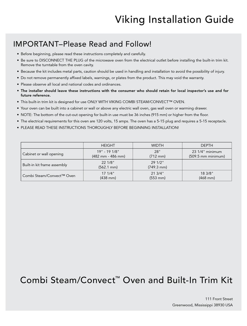
Viking Installation Guide
Built-In Electric
Combi Steam/Con ection O en
(CC082407J)
J690.160
Table of Contents
Warnings & Important Information
___________________________________________
2
Dimensions & Specifications (Professional Series)__________________________ 3
Dimensions & Specifications (Designer Series)_____________________________ 4
Cutout Dimensions (Professional & Designer Series) _______________________ 5
General Information ___________________________________________________ 6
Recommen ations for Moving _______________________________________ 6
Installation ___________________________________________________________ 7
Site Preparation ____________________________________________________ 7
Installation Proce ure _____________________________________________ 7-9
Trim Kit Specifications _________________________________________________ 9
Performance Checklist ________________________________________________ 10
Final Preparation _____________________________________________________ 11
Service & Parts____________________________________________________ 11
Electrical Requirements ____________________________________________ 12
Maximum Amp Usage _____________________________________________ 12
2
IMPORTANT–Please Read and Follow!
• Before beginning, rea these instructions
thoroughly an carefully.
• This unit inclu es metal parts, therefore,
caution shoul be use in the han ling
an installation of this pro uct to avoi
the possibility of injury.
• Do not remove permanently affixe labels,
warnings or plates from the pro uct as this
may voi the warranty.
• Observe all local an national co es,
requirements an or inances.
• Installation must conform with local co es
or in the absence of co es, the National
Electrical Co e, ANSI/NFPA 70 – latest
e ition.
• IN MASSACHUSETTS: This appliance must
be installe by a Massachusetts license
plumber or electrician.
• IN CANADA: Installation must be in
accor ance with the current CSA C22.1
Cana ian Electrical Co es Part 1 an /or
local co es.
• Installers shoul leave this gui e with the
consumer who shoul retain it for the local
inspector’s use an for future reference.
• Consumer shoul retain this gui e for the
local Electrical inspector’s use.
WARNING
DO NOT use the han le or appliance oor
to lift the appliance. Remove oor before
installation to ensure that it is not use to
lift the unit.
WARNING
The misuse of the appliance oor(s) (e.g.
stepping, sitting, or leaning on them) can
result in hazar s or injuries an amage to
the pro uct.
WARNING
ELECTRICAL GROUNDING INSTRUCTIONS
This appliance must be electrically in
accor ance with local co es, or groun e
in the absence of local co es, the National
Electrical ANSI/NFPA 70, latest e ition.
WARNING
The use of cabinets for storage above the
appliance may result in potential fire or
burn hazar .
WARNING
To re uce the risk of tipping the appliance,
the appliance must be secure by properly
installing anti-tip evices packe with the
appliance.
WARNING
The appliance shoul not be use for
space heating. This information is base on
safety consi erations.
WARNING
Frame groun e by a 3-con uctor cable
assembly. DO NOT use an extension cor
with this appliance. Such use may result in
fire, electrical shock, or other personal
injury.
WARNING
This appliance is heavy – use extreme care
when han ling!
Dimensions & Specifications (Designer Series)
43
Dimensions & Specifications (Professional Series)
23-3/8”
(59.4 cm)
14-15/16”
(37.9cm)
20-7/8”
(53.1 cm)
14-3/4”
(37.5 cm)
21-15/16”
(55.7 cm)
25-3/4”
(65.5 cm)
2-1/2”
(6.4 cm)1-3/8”
(3.4 cm)
23-3/8”
(59.4cm)
14-15/16”
(37.9cm)
20-7/8”
(53.1 cm)
14-3/4”
(37.5cm)
21-5/8”
(54.9 cm)
25-1/16”
(63.7 cm)
1-3/8”
(3.4 cm)
2-1/8”
(5.4 cm)
Professional Built-In Electric Combi Steam Convection Oven
Description |VCSO244
Overall wi th 23-3/8” (59.4 cm)
Overall wi th (with lateral hol ers) 23-3/4” (60.3 cm)
Overall height 14-15/16” (37.9 cm)
Overall epth (to the e ge of oor) 21-15/16” (55.7 cm)
Overall epth (to front of han les) 24” (62.1 cm)
Overall epth (from electrical) 25-3/4” (65.4 cm)
Cutout wi th 21-5/8” (65.5 cm)
Cutout height 15” (38.1 cm)
Cutout epth 22-1/16” (56.0 cm)
Electrical requirements 4 ft. (121.9 cm) flexible stainless steel con uit
4 – wire groun , 240 VAC, 16 amp electrical connection
Unit is equippe with No. 14 groun in unit
Maximum amp usage 16.0 amps – 240 VAC
13.9 amps – 208 VAC
Appliance interior wi th 12-1/8” (31.3 cm)
Appliance interior height 10-1/4” (26.0 cm)
Appliance interior epth 15-1/2” (39.3 cm)
Open cavity volume 1.1 cu. ft. (31 L)
Approximate shipping weight 73 lbs. (34 kg)
Designer Built-In Electric Combi Steam Convection Oven
Description |DCSO244
Overall wi th 23-3/8” (59.4 cm)
Overall wi th (with lateral hol ers) 23-3/4” (60.3 cm)
Overall height 14-15/16” (37.9 cm)
Overall epth (to the e ge of oor) 21-5/8” (54.9 cm)
Overall epth (to front of han les) 23-1/2” (60.3 cm)
Overall epth (from electrical) 25-1/16” (63.7 cm)
Cutout wi th 21-5/8” (54.9 cm)
Cutout height 15” (38.1 cm)
Cutout epth 22-1/16” (56.0 cm)
Electrical requirements 4 ft. (121.9 cm) flexible stainless steel con uit
4 – wire groun , 240 VAC, 16 amp electrical connection
Unit is equippe with No. 14 groun in unit
Maximum amp usage 16.0 amps – 240 VAC
13.9 amps – 208 VAC
Appliance interior wi th 12-1/8” (31.3 cm)
Appliance interior height 10-1/4” (26.0 cm)
Appliance interior epth 15-1/2” (39.3 cm)
Open cavity volume 1.1 cu. ft. (31 L)
Approximate shipping weight 72 lbs. (33 kg)
General Information
• All openings in the wall behin the oven
or in the floor un er the oven shoul be
seale .
• Keep oven area clear an free from
combustible materials, gasoline an other
flammable vapors.
• Turn off power an isconnect the
electrical supply prior to servicing or
cleaning.
• When removing the oven for service, turn
off power, isconnect AC power supply
an carefully remove the appliance by
pulling forwar .
• Electrical requirements are liste in the
pro uct specifications un er the electrical
requirements section.
• DO NOT remove protective packaging
until you are rea y to perform the
installation.
• DO NOT remove the protective wrapping
from the pro uct control panel until the
pro uct is installe .
Recommen ations for
Moving
• The appliance is heavy – use extreme care
when han ling!
6
Cutout Dimensions (Professional & Designer Series)
5
21-5/8”
(55.0cm)
to
21-13/16”
(55.4cm)
Wiring access
15”
(38.1 cm)
22-1/16”
(56.1 cm)min.
2-3/16”
(5.6 cm)
TrimOverlap
2”
(5.1 cm)
TrimOverlap
• Only proper equipment shoul be use to
move pro ucts.
• ALWAYS take steps to protect flooring at
the installation location when moving
pro ucts.
*Refer to the Use & Care Manual for
properly removing the oor.
C A U T I O N
This appliance is heavy – use extreme
care when han ling!
WARNING
DO NOT use the han le or appliance
oor to lift the appliance. Remove oor
before installation to ensure that it is not
use to lift the unit. Do ot lift or carry
the door by the ha dle.
Electrical Requirements
3/4-wire groun , 208-240V/60Hz
No. 14 groun wire in unit; 4 ft. cor
Installation
7 8
Place the oven in front of the cabinet opening.
1
2
3
4
Black
Strain
relief
Red
Green
5
6
Connect green wire from oven to the supply cable
groun wire insi e the junction box. Connect black an
re wires from oven to matching color wires from supply
cable in junction box.
Installation Proce ure
Site Preparation
NOTE: It is recommended that a thorough
site inspection be conducted PRIOR to
unpacking and moving this appliance.
*Refer to the Use & Care Manual for
properly removing the oor.
• Confirm available access to a equate
power – see electrical requirements.
• It is recommen e that 3/4" or larger
material be utilize to create a support
platform for this appliance.
•BE SURE that support for this appliance is
perpen icular to the front facing of the
wall or cabinet before you perform the
installation.
• All openings in the wall behin the oven
or in the floor un er the oven shoul be
seale .
• Keep oven area clear an free from
combustible materials, gasoline an other
flammable vapors.
Professional Trim KitProfessional Trim KitProfessional Trim Kit
7A
7B
Designer Trim KitDesigner Trim KitDesigner Trim Kit
Open the oven oor an attach the oven to the front of
the cabinet with 4 screws.
Open the oven oor. Pass the trim kit over the oor
towar s the front of the cabinet.
Insert oven into the cabinet opening. Push the oven in an against the cabinet until the lateral
hol ers of the oven touch the front of the cabinet. Avoi
pinching the con uit between the oven an the wall. Be sure
the oven is place at the center of the opening.
Fee the flexible cable con uit from the oven through
the opening in the cabinet.
Remove the junction box cover.
WARNING
DO NOT use the han le or appliance
oor to lift the appliance. Remove oor
before installation to ensure that it is not
use to lift the unit. Do ot lift or carry
the door by the ha dle.
WARNING
DO NOT use an extension cor with this
appliance. Such use may result in fire,
electrical shock or other personal injury.
9
Performance Checklist
10
The installer shoul carry out the following
performance checks:
hCheck & set clock
hCheck Steaming
hCheck Reheat Plus™ Function
hCheck ProBake Cooking
hCheck TruConvec™ Cooking
hCheck SteamHeat™ Cooking
hCheck TruSteam™ Cooking
Any a justments necessary that are a result
of the installer not following instructions will
be the responsibility of the installer, ealer
or the en user of the pro uct.
I staller’s i formatio :
Installer’s name:_____________________________
Installer’s company:_________________________
Date: ________________________________________
8A
Professional Trim KitProfessional Trim KitProfessional Trim Kit
Close oven oor an position the trim kit to be square
with the oven. Attach the trim kit frame with 4 screws to
the front of the cabinet.
Designer Trim KitDesigner Trim KitDesigner Trim Kit
8B
Position the trim kit to be square with the oven. Attach
the trim kit frame an the oven with 4 screws to the
front of the cabinet.
Trim Kit Specifications (Professional & Designer Series)
Model Overall Width Overall Height
VSTK274 26 1/2” (67.3 cm)
19 3/16” (48.7 cm)
VSTK304 29 1/2” (74.9 cm)
VSTK364 35 1/2” (90.2 cm)
DSTK274 26 1/2” (67.3 cm) 18 7/8” (48.0 cm)
DSTK304 29 1/2” (74.9 cm)
12
Electrical Requirements
4-wire groun , 208-240 VAC, 60 Hz
Unit equippe with No. 14 groun wire in unit
Maximum Amp Usage
16.0 amps – 240 VAC
13.9 amps – 208 VAC
11
Gree
Black
Black
Gree
Red
Red
240V 2~/16 A
208V 2~/13.9 A
Ju ctio box
1. The interior of the oven shoul be washe
thoroughly with hot, soapy water to
remove film resi ues an installation
ebris before being use for foo
preparation, then rinse an wipe ry.
Solutions stronger than soapy water are
rarely nee e .
2. Some stainless steel parts may have a
plastic protective wrap, which must be
remove . All stainless steel bo y parts
shoul be washe with hot soapy water
an with liqui cleaner esigne for this
material. If buil -up occurs, o not use
steel wool, abrasive cloths, cleaners or
pow ers! If it is necessary to scrape
stainless steel to remove encruste
materials, soak with hot, wet cloths to
loosen the material, then use a woo or
nylon scraper. Do not use a metal knife,
spatula, or any other metal tool to scrape
stainless steel!! Scratches are almost
impossible to remove.
Service & Parts
Only authorize replacement parts may be
use in performing service on the appliance.
Do not repair or replace any part of the
appliance unless specifically recommen e
in the manual. All other servicing shoul be
referre to a qualifie technician.
Contact Viking Range Corporation, (888)
845-4641, for the nearest service parts
istributor in your area.
Recor the following information in icate
below. You will nee it if service is ever
require . The serial number an mo el number
for your appliance are locate on the
i entification plate mounte on the insi e of
the water tank opening.
Mo el number
______________________________________________
Serial number
______________________________________________
Date of purchase
______________________________________________
Date installe
______________________________________________
Dealer's name
______________________________________________
A ress
______________________________________________
These installation instructions shoul remain
with the unit for future reference.
Final Preparation
1413

This manual suits for next models

3

Other Viking Oven manuals

Viking VESO5272BK User manual

Viking

Viking VESO5272BK User manual

Viking MVDOE630 User manual

Viking

Viking MVDOE630 User manual

Viking Professional VGSO100 User manual

Viking

Viking Professional VGSO100 User manual

Viking Combi Steam/Convect VSOC530SS User manual

Viking

Viking Combi Steam/Convect VSOC530SS User manual

Viking 3 Series User manual

Viking

Viking 3 Series User manual

Viking F20686 User manual

Viking

Viking F20686 User manual

Viking F20669B EN (011910) User manual

Viking

Viking F20669B EN (011910) User manual

Viking Professional VESO166BR User manual

Viking

Viking Professional VESO166BR User manual

Viking Professional Series User manual

Viking

Viking Professional Series User manual

Viking RDDOE306SS User manual

Viking

Viking RDDOE306SS User manual

Viking VEDO127 User manual

Viking

Viking VEDO127 User manual

Viking VESO5302BU User manual

Viking

Viking VESO5302BU User manual

Viking Professional Custom VESO1302BR User manual

Viking

Viking Professional Custom VESO1302BR User manual

Viking VSOE527 User manual

Viking

Viking VSOE527 User manual

Viking VCSO210 User manual

Viking

Viking VCSO210 User manual

Viking Professional VGSO166 User manual

Viking

Viking Professional VGSO166 User manual

Viking Professional VGSO100 User guide

Viking

Viking Professional VGSO100 User guide

Viking DrawerMicro VMOD241SS User manual

Viking

Viking DrawerMicro VMOD241SS User manual

Viking DrawerMicro VMOD5240 User manual

Viking

Viking DrawerMicro VMOD5240 User manual

Viking Professional VEDO266 User manual

Viking

Viking Professional VEDO266 User manual

Viking Designer DEDO127TSS User manual

Viking

Viking Designer DEDO127TSS User manual

Viking M0706VR User manual

Viking

Viking M0706VR User manual

Viking RVSOE User manual

Viking

Viking RVSOE User manual

Viking 27" Wide User manual

Viking

Viking 27" Wide User manual

Popular Oven manuals by other brands

Bosch HBR36B6.0 Instructions for use

Bosch

Bosch HBR36B6.0 Instructions for use

FIRST AUSTRIA FA-5046 instruction manual

FIRST AUSTRIA

FIRST AUSTRIA FA-5046 instruction manual

AEG BEK435060M user manual

AEG

AEG BEK435060M user manual

Siemens HB36LB 61 Series instruction manual

Siemens

Siemens HB36LB 61 Series instruction manual

Bravetti TO158BL owner's manual

Bravetti

Bravetti TO158BL owner's manual

NEFF C18FT34 0B Series instruction manual

NEFF

NEFF C18FT34 0B Series instruction manual

SEVERIN TISCH-BACKOFEN MIT HEIßLUFTFUNKTION TO... datasheet

SEVERIN

SEVERIN TISCH-BACKOFEN MIT HEIßLUFTFUNKTION TO... datasheet

Artusi AO654XP Operation manual

Artusi

Artusi AO654XP Operation manual

Thermador DM302ES installation instructions

Thermador

Thermador DM302ES installation instructions

IKEA IBS550P Use & care guide

IKEA

IKEA IBS550P Use & care guide

Whirlpool W4 OMSK58RU1SBA quick guide

Whirlpool

Whirlpool W4 OMSK58RU1SBA quick guide

Atag OI61 E Series Instructions for use

Atag

Atag OI61 E Series Instructions for use

Toastmaster 337 Use and care guide

Toastmaster

Toastmaster 337 Use and care guide

Zanussi ZOP38903 user manual

Zanussi

Zanussi ZOP38903 user manual

Bakers Pride FC-516 Installation and operating instructions

Bakers Pride

Bakers Pride FC-516 Installation and operating instructions

Landmann 825 Assembly instruction

Landmann

Landmann 825 Assembly instruction

Bosch HBN53R550B installation instructions

Bosch

Bosch HBN53R550B installation instructions

Lincat Silverlink 600 Installation, operating and servicing instructions

Lincat

Lincat Silverlink 600 Installation, operating and servicing instructions

manuals.online logo
manuals.online logoBrands
  • About & Mission
  • Contact us
  • Privacy Policy
  • Terms and Conditions

Copyright 2025 Manuals.Online. All Rights Reserved.