manuals.online logo
Brands
  1. Home
  2. •
  3. Brands
  4. •
  5. Viking
  6. •
  7. Wine Cooler
  8. •
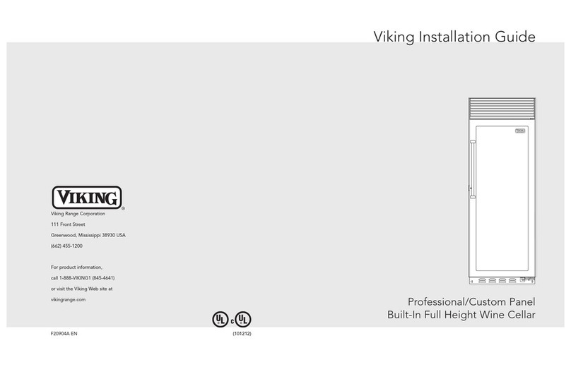
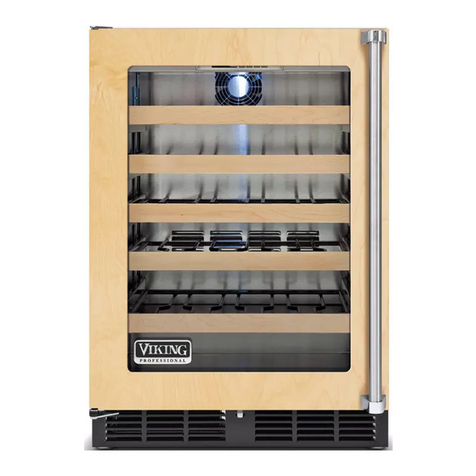
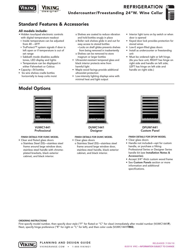
  9. Viking Designer DFUW142 User manual

Viking Designer DFUW142 User manual

Other manuals for Designer DFUW142

3

This manual suits for next models

4

Other Viking Wine Cooler manuals

Viking DFWB300R User manual

Viking

Viking DFWB300R User manual

Viking VWUI5151G User manual

Viking

Viking VWUI5151G User manual

Viking 24" Technical manual

Viking

Viking 24" Technical manual

Viking VCWB301RSS User manual

Viking

Viking VCWB301RSS User manual

Viking PW200001 Service manual

Viking

Viking PW200001 Service manual

Viking FDWB301R User manual

Viking

Viking FDWB301R User manual

Viking DDWB301CRSS User manual

Viking

Viking DDWB301CRSS User manual

Viking DDWB301CRSS User manual

Viking

Viking DDWB301CRSS User manual

Viking VCWB301 User manual

Viking

Viking VCWB301 User manual

Viking Designer DFUW2441CR Manual

Viking

Viking Designer DFUW2441CR Manual

Viking 15" (38.1 cm) Technical manual

Viking

Viking 15" (38.1 cm) Technical manual

Viking VCWB301R User manual

Viking

Viking VCWB301R User manual

Viking Designer DFUW1441CR Manual

Viking

Viking Designer DFUW1441CR Manual

Viking DFUW144 User manual

Viking

Viking DFUW144 User manual

Viking Designer DFUW1441CR Technical manual

Viking

Viking Designer DFUW1441CR Technical manual

Viking VDUI5241 User manual

Viking

Viking VDUI5241 User manual

Viking VCWB301 User manual

Viking

Viking VCWB301 User manual

Viking FWCI1150GR Manual

Viking

Viking FWCI1150GR Manual

Viking Designer DDWB300 User manual

Viking

Viking Designer DDWB300 User manual

Viking Designer DDWB300 User manual

Viking

Viking Designer DDWB300 User manual

Viking VWUI5150 User manual

Viking

Viking VWUI5150 User manual

Viking VCWB300RSS Reference guide

Viking

Viking VCWB300RSS Reference guide

Viking Designer DFUW142 User manual

Viking

Viking Designer DFUW142 User manual

Viking VCWB301R User manual

Viking

Viking VCWB301R User manual

Popular Wine Cooler manuals by other brands

Caple WI152 technical information

Caple

Caple WI152 technical information

Sub-Zero WS-30 Specification sheet

Sub-Zero

Sub-Zero WS-30 Specification sheet

Rotel U903CH1 Instructions for use

Rotel

Rotel U903CH1 Instructions for use

Esatto EWC46 quick start guide

Esatto

Esatto EWC46 quick start guide

Sub-Zero Classic Series installation guide

Sub-Zero

Sub-Zero Classic Series installation guide

U-Line Echelon Wine Captain 2075WC Features & benefits

U-Line

U-Line Echelon Wine Captain 2075WC Features & benefits

Haier WS50GA user manual

Haier

Haier WS50GA user manual

Caple WC6511 instruction manual

Caple

Caple WC6511 instruction manual

Cavist 62 instruction manual

Cavist

Cavist 62 instruction manual

Kenmore 461.99130 owner's manual

Kenmore

Kenmore 461.99130 owner's manual

Caple Wi6128 instruction manual

Caple

Caple Wi6128 instruction manual

Danby DWC113BLSDB owner's manual

Danby

Danby DWC113BLSDB owner's manual

Avanti WC1001 instruction manual

Avanti

Avanti WC1001 instruction manual

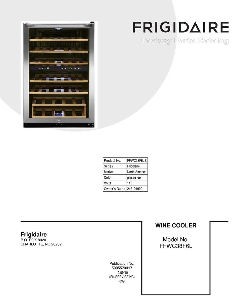
Frigidaire FFWC38F6LS Factory parts catalog

Frigidaire

Frigidaire FFWC38F6LS Factory parts catalog

Titan TT-W2454SZ User guide & service manual

Titan

Titan TT-W2454SZ User guide & service manual

Klarstein Botella 166 Uno manual

Klarstein

Klarstein Botella 166 Uno manual

Costway FP10130WL manual

Costway

Costway FP10130WL manual

Lemair LWC59 instruction manual

Lemair

Lemair LWC59 instruction manual

manuals.online logo
manuals.online logoBrands
  • About & Mission
  • Contact us
  • Privacy Policy
  • Terms and Conditions

Copyright 2025 Manuals.Online. All Rights Reserved.

USE/INSTALLATION
INSTRUCTIONS
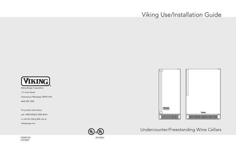
24” W. UNDERCOUNTER/FREESTANDING WINE CELLAR
Retain for Future Reference
IMPORTANT - PLEASE READ AND FOLLOW
•• Before beginning, please read these instructions completely and carefully.
• Do not remove permanently affixed labels, warnings, or plates from the product. This may void the warranty.
• Please observe all local and national codes and ordinances.
• Please ensure that this product is properly grounded.
• The installer should leave these instructions with the consumer who should retain for local inspector’s use and for
future reference.
WARNING::
TToo rreedduuccee tthhee rriisskk ooff ffiirree,, eelleeccttrriiccaall sshhoocckk,, oorr iinnjjuurryy wwhheenn uussiinngg yyoouurr wwiinnee cceellllaarr,, ffoollllooww bbaassiicc pprreeccaauuttiioonnss iinncclluuddiinngg tthhee
ffoolllloowwiinngg::•FOR YOUR SAFETY•
DO NOT STORE OR USE GASOL NE OR OTHER FLAMMABLE VAPORS AND L QU DS N THE V C N TY OF TH S OR
ANY OTHER APPL ANCE. THE FUMES CAN CREATE A F RE HAZARD OR EXPLOS ON.
tt iiss yyoouurr rreessppoonnssiibbiilliittyy ttoo bbee ssuurree yyoouurr wwiinnee cceellllaarr iiss::
•located so the front is not blocked to restrict incoming or discharge air flow.
•properly leveled.
•located in a well ventilated area.
•connected to the proper kind of outlet, with the correct electric supply and grounding. A 115 volt, 60 Hz, 15 amp
fused electrical supply is required. NNOOTTEE::Time delay fuse or circuit breaker is recommended.
•not used by anyone unable to operate it properly.
•used only for its intended purpose.
•properly maintained.
•SAVE THESE INSTRUCTIONS•
41009332
Rev. C
DANGER
SUFFOCATION HAZARD
Remove doors from our old
refrigeration unit.
Failure to do so can result in
child entrapment, which can
cause death or brain damage.
IMPORTANT: Child entrapment and suffocation are not problems of the
past. Junked or abandoned refrigeration products are still dangerous,
even if the will sit for “just a few da s.” If ou are getting rid of our
refrigeration product, please follow the instructions below to help prevent
accidents.
BEFORE YOU THROW AWAY YOUR OLD REFRIGERATION UNIT:
•Take off the doors.
•Leave the shelves in place so that children may not easily climb inside.
PROPER DISPOSAL OF YOUR OLD REFRIGERATION UNIT
2
GENERAL INFORMATION
UUnnppaacckk
1. Remove banding from bottom of carton. Lift carton up and off of the wine cellar
2. Remove all tape and packaging material from the outside and inside of the cabinet.
3. Keep all carton packaging until your wine cellar has been thoroughly inspected and found to be in good condition.
AARREEAA RREEQQUURREEMMEENNTTSS
1. Place unit so the front side will be completely unobstructed to provide proper air flow. The unit may be closed in
on the top and three sides, but the front MMUUSSTT BBEEunobstructed for air circulation and proper operation.
nstallation should be such that the cabinet can be moved for servicing if necessary.
2. Unit should be in a well ventilated area with temperature above 550F (130C) and below 1100F (430C). Best results
are obtained at temperatures between 650F (180C) and 800F (270C) for built-in models and 650F (180C) and 900F
(320C) for freestanding models.
3. Provisions for electricity should be determined before placing unit in proper place.
A
B
C
UUNNDDEERRCCOOUUNNTTEERR CCAABBNNEETT CCUUTTOOUUTT
AA24” (61.0 cm)*
BBMin. 34 1/2” (87.6 cm)
Max. 35 1/8” (89.2 cm)
CC24” (61.0 cm)
*24” width for cabinet only. 24 1/4” (61.6 cm)
need for cabinet and door width clearance if
door is recessed between cabinets.
3
SPECIFICATIONS/DIMENSIONS
PROFESSIONAL SERIES
BBaassiicc EElleeccttrriicc DDaattaa
•115 VAC/60 Hz
•Maximum amps - 3.3
•Approximate Shipping Weight - 140 lbs. (63.2 kg)
Min. 34 1/4”
(87.0 cm) Max
35” (88.9 cm)
with leveling
legs fully
extended
30 3/4”
(78.1 cm)
23 7/8” (60.6 cm)
47 1/4” (120.0 cm)
22” (55.9 cm)
24 3/8” (61.9 cm)
26 7/8” (68.3 cm)
4
SPECIFICATIONS/DIMENSIONS
DESIGNER SERIES
BBaassiicc EElleeccttrriicc DDaattaa
•115 VAC/60 Hz
•Maximum amps - 3.3
•Approximate shipping weight - 140 lbs (63.2 kg)
Front View
30 3/4”
(78.1 cm)
Mín.
34 1/4”
(87.0 cm)
Max.
35”
(88.9 cm)
with leveling
legs fully
extended
23 7/8” (60.6 cm)
Side View
DUWC
22” (55.9 cm)
24 3/8” (61.9 cm)
25 3/8” ( 64.5 cm)
47 1/4” (120.0 cm)
Side View
DFUW
22” (55.9 cm)
24 3/16” (61.4 cm)
47 1/4” (120.0 cm)
(to front of locally supplied
custom panel
5
CUSTOM WOOD FRAME INSTALLATION INSTRUCTIONS
((DDFFUUWW MMooddeell))
Note: Weight of wood panel must not exceed 20 lbs.
WWoooodd SSccrreewwss
1. A #10 pan head wood screw should be used to properly secure the wood frame. A total of 10 screws will be needed
for a 3 1/2” (8.9 cm) kickplate or 8 screws for a 4” (10.2 cm) kickplate.
2. Only use pan head screws.
3. DO NOT select a screw that is longer than the wood thickness at
the screw locations.
4. Use recommended pilot holes for the frame material. (See chart)
WWoorrkkiinngg MMaatteerriiaallWWoooodd SSccrreeww SSiizzee ##1100
Hardwood 3/32 (0.24 cm)
Softwood 5/64 (0.20 cm)
AAsssseemmbblliinngg DDoooorr HHiinnggee BBrraacckkeettss
(Disregard if hinge brackets are already attached)
1. Attach the top and bottom door hinge brackets to the door with the #10-32 machine screws and a 1/8” allen head
driver as shown in Figure 1 below.
2. Press in the shoulder bushings to the top and bottom door hinge brackets. Make certain that the shoulder is to the
outside of the door as shown in Figure 1 below.
3. Test fit the door to the unit to make certain door will hang correctly. The door is hung correctly when the top of the
door is parallel to the top of the unit. (See Figure 2) Adjustments can be made by loosening the door hinge
machine screws and moving the door hinge brackets on the door.
4. Tighten all four (4) machine screws after adjustments have been made.
5. Remove the door from the unit by removing the units top hinge set screw and angling the door off of the bottom
hinge pin.
Figure 1
Shoulder Bushing
Door Hinge Bracket
#10-32 Machine
Screw
Door Hinge
Screw Holes
Door Front
Surface
TTyyppiiccaall TToopp aanndd BBoottttoomm
DDoooorr HHiinnggee BBrraacckkeett
AAsssseemmbbllyy
Figure 2
This surface parallel to the unit.
(Right hinge door shown
6
Selecting and Preparing the Wood Frame - DFUW Model
FFOORR AA 33--11//22”” TTOOEE KKCCKK
((CCOOVVEERRSS TTHHEE EENNTTRREE DDOOOORR EEXXTTRRUUSSOONN))
((LLEEFFTT HHNNGGEE))
7 13/16” (19.8 cm)
7
FFOORR AA 33--11//22”” TTOOEE KKCCKK
((CCOOVVEERRSS TTHHEE EENNTTRREE DDOOOORR EEXXTTRRUUSSOONN))
((RRGGHHTT HHNNGGEE))
7 13/16” (19.8 cm)
8
Attaching the Wood Frame to the Door - DFUW Model
1. f the door is attached to the unit, remove by unscrewing the top allen head set screw at the top hinge. Remove
the door by angling the door off of the bottom hinge pin.
2. nstall the supplied lock body into the wood panel. Secure the lock body by using the supplied 15mm lock
retaining nut. Screw the retaining nut onto the lock body’s threaded section. Make sure the lock’s key slot is
vertical, then tighten the nut with a 15mm deep well socket.
3. Peel back the door gasket to expose the screw holes and lock location hole.
4. Set the wood frame flush to the front of the door in the desired location. Clamp the wood frame to the door if
necessary. Check to make sure the back of the lock in the wood frame lines up with the hole in the door.
5. nsert the wood screws through the back of the door into the pilot holes in the wood frame and tighten.
6. Assemble the door lock’s phillips head screw, lock extension, and lock cam. Mount them to the back of the lock
body. The cam should be oriented vertically. Tighten the phillips head screw to secure the lock assembly.
7. Reinstall the door gasket by pressing into the door channel. Make certain the corners are inserted fully. nsert the
key into the lock and make sure lock operates properly.
8. nstall the door to the unit. Use the supplied plastic washer as shown in the figure below.
9. Realigning the door may be necessary. Any final door adjustments can be made using a 1/8” allen head driver to
adjust the door’s hinges. (See figure below)
10. Attach the door light striker plate as shown using the 5/16” hex or phillips head screws provided. Make certain the
light is able to turn on and off when the door is opened and closed.
11. Attach the door to the unit by reversing step number 1 above.
12. nsert the key into the lock and verify that the lock cam works properly with the catch bracket on the cabinet front.
CAUT ON
Door can become
disengaged if washers
are not installed.
CAUT ON
Door can become
disengaged if
washers are not
installed.
Cabinet
Hinge
Wood
Frame
Door Hinge
Shoulder bushing
3/4” OD x 7/16”
D Washer
3/4” OD x 1/4” D
Washer
(3) Nylon hardware
components at
bottom hinge
CAUT ON
Door may not swing properly
if all nylon components are
not installed as shown
Bottom Hinge Cover
Wood Frame
HHiinnggee HHaarrddwwaarree nnssttaallllaattiioonn DDeettaaiillss
Magnetic door
gasket
Rear of Door
Bottom of door
Attached wood frame
5/8”x 7/32” D washer
Shoulder
bushing
3/8” clearance
holes for
frame wood
screws -
10 holes
(2) Nylon
hardware
components at
top hinge
Top Hinge Cover
1/8” allen head screws for hinge
adjustment
Door Hinge
Door hinge
adjustment screws
Door light striker plate
9
LEG LEVELER INSTALLATION
Read before installing leg levelers
WWAARRNNNNGG:: Do not lay unit on top, side, back, or front. f unit is
accidentally laid in any position other than right side up, then the unit
must remain in the right side up position for at least 24 hours before
plugging the unit in.
1. Tip unit backwards so there is one foot of clearance on front of the
unit. Have someone to assist you in tilting the unit to prevent it from
falling on you while installing the leg levelers.
2. Screw front two (2) leg levelers into the weldnuts. Leg levelers
should be screwed in until snug.
3. Repeat steps 1 & 2 with the exception of tipping the unit forwards to
screw in the back two leg levelers.
4. The leg levelers are not installed.
5. The unit should be level from front to back and side to side. f floor
conditions do not allow the unit to sit level, adjust the leg levelers by
turning the required leg leveler counter-clockwise to increase the
height and clockwise to reduce the height.
Weldnut
(Each bottom
corner of unit)
Leg Leveler
(4) per unit
Lock Installation Details
L
Lo
oc
ck
k
B
Bo
od
dy
y
LLoocckk CCaamm
P
Ph
hi
il
ll
li
ip
ps
s
S
Sc
cr
re
ew
w
L
Lo
oc
ck
k
E
Ex
xt
te
en
ns
si
io
on
n
L
Lo
oc
ck
k
R
Re
et
ta
ai
in
ne
er
r
N
Nu
ut
t
KKEEYY
DDoooorr GGaasskkeett
GGllaassss DDoooorr
WWoooodd PPaanneell
10
ELECTRICAL CONNECTION
EElleeccttrriiccaall RReeqquuiirreemmeennttss
A 115 volt, 60 Hz, AC only 15 amp fused electrical supply is required. (A time
delay fuse or circuit breaker is recommended.) t is recommended that a
separate circuit, serving only this appliance, be provided.
••EELLEECCTTRRCCAALL GGRROOUUNNDD SS RREEQQUURREEDD OONN TTHHSS AAPPPPLLAANNCCEE..
••DDOO NNOOTT UUNNDDEERR AANNYY CCRRCCUUMMSSTTAANNCCEESS RREEMMOOVVEE TTHHEE PPOOWWEERR SSUUPPPPLLYY
CCOORRDD GGRROOUUNNDD PPLLUUGG..
••DDOO NNOOTT UUSSEE AANN EEXXTTEENNSSOONN CCOORRDD..
RReeccoommmmeennddeedd GGrroouunnddiinngg MMeetthhooddss
For your personal safety, this wine cellar must be grounded. This appliance is equipped with a 7’ (2.1 m) power supply cord
having a 3-prong grounding plug. To minimize possible shock hazard, the cord must be plugged into a mating 3-prong
grounding type wall receptacle grounded in accordance with the National Electrical Code and local codes and ordinances. f
the circuit does not have a grounding type receptacle, it is the responsibility and obligation of the customer to exchange the
existing receptacle in accordance with the National Electrical Code and applicable local codes and ordinances. The third
ground plug SHOULD NOT, under any circumstances, be cut or removed. All UL listed refrigerated products are equipped
with this type of plug.

Power Supply
with 3-prong
grounding plug
Grounding type wall
receptacle
FINAL PREPARATION
1. Some stainless steel parts may have a plastic protective wrap which must be peeled off. The interior of the wine cellar
should be washed thoroughly with hot, soapy water, rinsed and wiped dry to remove film residue and any installation dust
or debris before being used. Solutions stronger than soap and water are rarely needed.
2. All stainless steel parts should be wiped with hot soapy water. f buildup occurs, do not use steel wool, abrasive cloths,
cleaners, or powders. f it is necessary to scrape stainless steel to remove encrusted materials, soak with hot, wet cloths to
loosen the material, then use a wood or nylon scraper. Do not use a metal knife, spatula, or any other metal tool to scrape
stainless steel; scratches are almost impossible to remove.
WARNING ELECTRICAL SHOCK HAZARD
Failure to follow these instructions could result in fire or electrical shock.
WIRING DIAGRAM
UNDERCOUNTER/FREESTANDING 24” W. WINE CELLAR
WWAARRNNNNGG:: EELLEECCTTRRCCAALL
GGRROOUUNNDDNNGG
NNSSTTRRUUCCTTOONNSS
This appliance is equipped with a
three prong grounding plug for
your protection against shock
hazard and should be plugged
directly into a properly grounded
three prong receptacle. Do not
cut or remove the grounding
prong from this plug.