manuals.online logo
Brands
  1. Home
  2. •
  3. Brands
  4. •
  5. Vimar
  6. •
  7. Intercom System
  8. •
  9. Vimar ELVOX 887U Assembly instructions

Vimar ELVOX 887U Assembly instructions

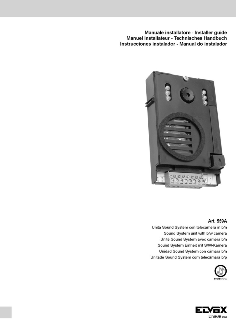
Manuale installatore - Installer guide
Manuel installateur - Technisches Handbuch
Instrucciones instalador - Manual do instalador
887U
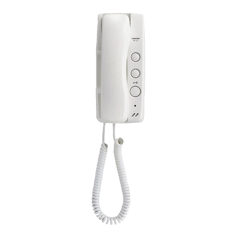
Citofono da parete universale
Universal wall-mounted interphone
Portier en saillie univers.
Universal-AP-Haustelefon
Portero autom. superf. universal
Porteiro autom. de mesa universal
8870
2
IT
8870
Descrizione
L’articolo 887U è un citofono universale utilizzabile indifferen-
temente in impianti di tipo tradizionale con chiamata in C.A.,
oppure in impianti con chiamata elettronica tipo Sound Sy-
stem.
Il citofono universale è compatibile con la maggior parte dei
citofoni presenti sul mercato mondiale, per cui rappresenta la
soluzione ideale per sostituire un vecchio apparecchio senza
dover intervenire su tutto l’impianto. Per effettuare i collega-
menti ed i settaggi vedi la tabella di compatibilità a pag. 10, 11.
Il citofono è provvisto di un pulsante apriporta, di trimmer per
poter ottimizzare il livello fonico sul microtelefono.
ELVOX TIENE A PRECISARE CHE in impianti già esistenti
il livello fonico, sia in trasmissione che in ricezione, potrebbe
risultare non ottimale qualora vi siano altri apparecchi difettosi
che mantengano inopportunamente il gancio aperto.
Settaggi e regolazioni
Per effettuare i settaggi e le regolazioni è necessario accedere
alla scheda elettronica posta sul fondo metallico dell’apparec-
chio. I settaggi consistono nel posizionamento di due ponticelli
al fine di scegliere il tipo di chiamata ed il riferimento comune
dell’impianto. Agendo con un cacciavite sui due trimmer R1
ed R2 è possibile ottimizzare il livello fonico interno del mi-
crotelefono.
CN4 morsettiera di collegamento
CN5 connettore per la selezione del tipo di chiamata
CN6 ponticelli per la selezione del comune positivo
oppure negativo
R1 trimmer per la regolazione del volume esterno
R2 trimmer per la regolazione del volume interno
Morsettiera di collegamento CN4
1 altoparlante
2 microfono
3 comune
6 chiamata
7 serratura
Settaggio tipo di chiamata (connettore CN5)
Seguire la tabella sottostante per selezionare il tipo di chia-
mata adatto all’impianto.
La chiamata in C.A. utilizza un ronzatore; la chiamata elettro-
nica utilizza l’altoparlante del microtelefono a riposo.
Il manuale istruzioni è scaricabile dal sito www.vimar.com
JUMPER POSIZIONATO
TRA “E” e IL CENTRALE
DEL CONNETTORE CN5
(fig. 1)
CHIAMATA
ELETTRONICA
(CITOFONI ELVOX
tecnologia Sound System)
JUMPER POSIZIONATO
TRA “C.A.” e IL CENTRALE
DEL CONNETTORE CN5
(fig. 1)
CHIAMATA IN C. A.
Settaggio Comune Impianto (connettore
CN6)
Seguire la tabella sottostante per la selezione del riferimento
COMUNE dell’impianto. Generalmente il riferimento comune è
il negativo (-), come per tutti gli impianti ELVOX, ma in alcuni
casi, il riferimento può esser positivo (+).
JUMPER TRA “-“ e “C” DEL
CONNETTORE CN6 (fig. 1)
COMUNE NEGATIVO (-)
JUMPER TRA “+” e “C” DEL
CONNETTORE CN6 (fig. 1)
COMUNE POSITIVO (+)
Regolazione fine del volume esterno ed in-
terno
SI PRECISA che la regolazione primaria dei livelli fonici è
principalmente gestita dall’alimentatore e/o dal posto fonico
esterno dell’impianto. Per ottimizzare il livello fonico sul micro-
telefono è possibile agire sui trimmer R1 ed R2 (vedi fig. 1).
Con R1 si ottimizza il guadagno del microfono (VOL. EST.),
mentre con R2 si ottimizza il livello fonico del ricevitore (VOL.
INT.).
Valori d’impedenza degli altoparlanti
IMPEDENZA
ALTOPARLANTE DELLA
CHIAMATA ELETTRONICA
16 OHM
IMPEDENZA
ALTOPARLANTE
MICROTELEFONO
REGOLABILE DA 16
OHM A CIRCA 120 OHM
TRAMITE TRIMMER R2
3
EN
8870
Description
Article 887U is a universal interphone that can be used either
in conventional systems with AC call or in installations with
electronic call (Sound System type). The universal interphone
is compatible with most interphones on the world market so
it’s the ideal solution to replace an obsolete appliance without
having to renew the entire entrance system. For details of con-
nections and settings refer to the compatibility table on page
10, 11. The interphone is equipped with a door lock control
button and trimmer to optimise speech volume on the handset.
IMPORTANT NOTE FROM ELVOX:
in existing systems the speech volume level in both transmis-
sion and reception may be impaired due to the presence of
defective units on which the speech circuit remains open due
to a fault.
Settings and adjustments
To make the necessary settings and adjustments access
the circuit board mounted on the metal base of the unit. The
settings consist in setting two jumpers that serve to choose
the type of call and the common reference of the installation.
Adjust trimmers R1 and R2 with a screwdriver to optimise the
speech level on the handset.
CN4 terminal board
CN5 connector for call type selection
CN6 jumpers for selection of negative or positive
common connection
R1 trimmer for external volume adjustment
R2 trimmer for internal volume adjustment
Terminal Board CN4
1 loudspeaker
2 microphone
3 common
6 call
7 lock
Call type setting (connector CN5)
Adhere to the following table to select the appropriate type in
relation to the plant.
The AC call uses a buzzer; the electronic call uses the loud-
speaker in the handset in the rest position.
The instruction manual is downloadable from the site www.vi-
mar.com
JUMPER SET BETWEEN “E”
and CENTRAL PIN OF
CONNECTOR CN5 (fig. 1)
ELECTRONIC CALL
(ELVOX Sound
System technology
INTERPHONES)
JUMPER SET BETWEEN
“C.A.” and CENTRAL PIN OF
CONNECTOR CN5 (fig. 1)
AC CALL
Installation common setting (connector CN6)
Adhere to the following table for selection of the installation’s
COMMON reference. Generally the common reference is the
negative (-), as for all ELVOX systems, but in some cases the
installation may have a positive (+) reference.
JUMPER BETWEEN “-“ and
“C” OF CONNECTOR CN6
(fig. 1)
NEGATIVE COMMON (-)
JUMPER BETWEEN “+” and
“C” OF CONNECTOR CN6
(fig. 1)
POSITIVE COMMON (+)
Fine adjustment of internal and external vol-
ume
NOTE that the primary adjustment of speech volume levels is
mainly dependent on the power supply and/or external speech
unit of the system. To optimise the speech volume level on
the handset use trimmers R1 and R2 (see fig. 1). Microphone
gain (VOL. EXT.) can be optimised with R1, while R2 serves to
optimise the speech volume level of the receiver (VOL. INT.).
Loudspeaker impedance values
ELECTRONIC CALL
LOUDSPEAKER
IMPEDANCE
16 OHM
HANDSET LOUDSPEAKER
IMPEDANCE
ADJUSTABLE FROM 16
OHM TO APPROX. 120
OHM BY MEANS OF
TRIMMER R2
4
FR
8870
Description
L’appareil 887U est un interphone universel pouvant être
utilisé indifféremment dans des systèmes traditionnels avec
appel en C.A. ou dans des systèmes avec appel électronique
du type Sound System. L’interphone universel étant compa-
tible avec la plupart des interphones en vente sur le marché
mondial représente la solution idéale pour remplacer un vieil
appareil sans devoir intervenir sur toute l’installation. Pour
effectuer les connexions et les réglages, voir le tableau de
compatibilité à page 10, 11. L’interphone est doté d’un bouton
pour l’ouverture de la porte et d’un trimmer pour l’optimisation
du niveau du son sur le microtéléphone.
ELVOX TIENT À PRÉCISER QUE sur des installations déjà
existantes, le niveau du son pourrait ne pas être optimal, aussi
bien en transmission qu’en réception, en cas de présence
d’autres appareils défectueux qui maintiendraient inopportu-
nément le pêne ouvert.
Réglages
Pour effectuer les réglages, il est nécessaire d’accéder à la
carte électronique positionnée sur le fond métallique de l’ap-
pareil. Les réglages consistent à positionner deux ponts afin
de choisir le type d’appel et la référence commune de l’ins-
tallation. Pour optimiser le niveau du son interne du micro-
téléphone, intervenir sur les deux trimmers R1 et R2 à l’aide
d’un tournevis.
CN4 bornier de connexion
CN5 connecteur pour la sélection du type d’appel
CN6 ponts pour la sélection du commun positif ou négatif
R1 trimmer pour le réglage du volume externe
R2 trimmer pour le réglage du volume interne
Bornier de connexion CN4
1haut-parleur
2microphone
3commun
6appel
7gâche
Réglage type d’appel (connecteur CN5)
Suivre les indications du tableau ci-dessous pour sélectionner
le type d’appel adapté à l’installation.
L’appel en C.A. fonctionne avec un ronfleur tandis que l’appel
électronique fonctionne avec le haut-parleur du microtélé-
phone au repos.
Télécharger le manuel d’instructions sur le site www.vimar.com CÂBLE DE JONCTION
POSITIONNÉ ENTRE « E »
et LE PEIGNE CENTRAL DU
CONNECTEUR CN5 (fig. 1)
APPEL ÉLECTRONIQUE
(INTERPHONES ELVOX
technologie Sound System)
CÂBLE DE JONCTION
POSITIONNÉ ENTRE « C.A. »
et LE PEIGNE CENTRAL DU
CONNECTEUR CN5 (fig. 1)
APPEL EN C. A.
Réglage commun installation (connecteur
CN6)
Suivre les indications du tableau ci-dessous pour sélectionner
la référence COMMUNE de l’installation. La référence com-
mune représente généralement le négatif (-), comme pour
toutes les installations ELVOX, mais elle peut, dans certains
cas, représenter le positif (+).
CÂBLE DE JONCTION
ENTRE « - » et « C » DU
CONNECTEUR CN6 (fig. 1)
COMMUN NÉGATIF (-)
CÂBLE DE JONCTION
ENTRE « + » et « C » DU
CONNECTEUR CN6 (fig. 1)
COMMUN POSITIF (+)
Réglage fin du volume externe et interne
À NOTER que le réglage primaire des niveaux sonores est
principalement géré par l’alimentateur et/ou par le poste ex-
terne téléphonique de l’installation. Pour optimiser le niveau
sonore sur le microtéléphone, agir sur les trimmers R1 et R2
(voir fig. 1). R1 permet d’optimiser le gain du microphone
(VOL. EXT.), tandis que R2 permet d’optimiser le niveau so-
nore du récepteur (VOL. INT.).
Valeurs d’impédance des haut-parleurs
IMPÉDANCE HAUT-PARLEUR
DE L’APPEL ÉLECTRONIQUE
16 OHM
IMPÉDANCE HAUT-PARLEUR
MICROTÉLÉPHONE
RÉGLABLE DE 16 OHMS
À ENVIRON 120 OHMS AU
MOYEN DU TRIMMER R2
5
DE
8870
Beschreibung
Das Universal-Haustelefon Art. 887U kann ohne Unterschied
in herkömmlichen Anlagen mit Wechselstromruf oder in Anla-
gen mit elektronischem Ruf vom Typ Sound System verwen-
det werden.
Das Universal-Haustelefon ist mit den meisten auf dem Welt-
markt erhältlichen Haustelefonen kompatibel, deshalb ist es
die ideale Lösung, um einen alten Apparat zu ersetzen, ohne
die ganze Anlage umbauen zu müssen. Für die Durchführung
der Anschlüsse und Einstellungen wird auf die Kompatibili-
tätstabelle auf Seite 410, 11verwiesen. Das Haustelefon ist
mit Türöffner, und zur Optimierung der Tonstufe am Hörer mit
einem Trimmer ausgestattet.
ELVOX WEIST AUSDRÜCKLICH DARAUF HIN, dass die
Tonstufe sowohl in der Übertragung als auch im Empfang bei
bereits existierenden Anlagen unter Umständen nicht optimal
ist, wenn andere defekte Apparate vorhanden sind, die den
Hörer fälschlicherweise abgehoben halten.
Einrichten und Einstellen
Um das Gerät einzurichten und einzustellen, ist der Zugang
zur Elektronikplatine an dessen Metallboden erforderlich. Das
Einrichten besteht aus dem Anbringen von zwei Steckbrücken,
mit denen die Rufart und der gemeinsame Referenzkontakt
der Anlage gewählt wird. Durch Verstellen der beiden Trim-
mer R1 und R2 mit einem Schraubenzieher kann die interne
Tonstufe des Hörers optimiert werden.
CN4 Anschlussklemmenleiste
CN5 Steckverbinder für die Wahl der Rufart
CN6 Steckbrücken für die Wahl des gemeinsamen Plus-
bzw. Negativkontakts
R1 Trimmer für die Regelung der Außenlautstärke
R2 Trimmer für die Regelung der Innenlautstärke
Anschlussklemmenleiste CN4
1 Lautsprecher
2 Mikrofon
3 Gemeinsamer Kontakt
6 Ruf
7 Türschloss
Einrichten der Rufart (Steckverbinder CN5)
Bei der Wahl der für die Anlage geeigneten Rufart ist die
nachstehende Tabelle zu befolgen. Der Wechselstromruf ver-
wendet einen Summer; der elektronische Ruf verwendet den
Lautsprecher des Hörers in Ruhestellung.
Die Bedienungsanleitung ist auf der Website www.vimar.com
zum Download verfügbar
ZWISCHEN “E” UND DEM
MITTLEREN KONTAKTFIN-
GER DES STECKVERBIN-
DERS CN5 POSITIONIERTER
JUMPER (Abb. 1)
ELEKTRONISCHER RUF
(ELVOX HAUSTELEFONE
mit Sound System
Technologie)
ZWISCHEN “AC” UND DEM
MITTLEREN KONTAKTFIN-
GER DES STECKVERBIN-
DERS CN5 POSITIONIERTER
JUMPER (Abb. 1)
WECHSELSTROMRUF
Allgemeines Einrichten der Anlage (Steck-
verbinder CN6)
Bei der Wahl des gemeinsamen Referenzkontakts der Anlage
ist die nachstehende Tabelle zu befolgen. Im Allgemeinen ist
die Referenz der Minuskontakt (-) wie bei allen Anlagen von
ELVOX, aber in einigen Fällen kann die Referenz auch der
Pluskontakt (+) sein.
JUMPER ZWISCHEN “-“ und
“C” DES STECKVERBINDERS
CN6 (Abb. 1)
GEMEINSAMER
NEGATIVKONTAKT (-)
JUMPER ZWISCHEN “+” und
“C” DES STECKVERBINDERS
CN6 (Abb. 1)
GEMEINSAMER PLUSKON-
TAKT (+)
Feineinstellung der Aussen- und Innenlaut-
stärke
ES IST ZU BEACHTEN, dass die primäre Einstellung der Ton-
stufen hauptsächlich vom Netzgerät und/oder von der exter-
nen Audiostelle der Anlage geregelt wird.
Um die Tonstufe am Hörer zu optimieren, können die Trimmer
R1 und R2 verstellt werden (siehe Abb. 1). Mit R1 wird die
Verstärkung des Mikrofons optimiert (LAUTST. AUSSEN), mit
R2 wird hingegen die Tonstufe des Hörers optimiert (LAUTST.
INNEN).
Impedanzwerte der Lautsprecher
LAUTSPRECHERIMPEDANZ
DES ELEKTRONISCHEN
RUFS
16 OHM
LAUTSPRECHERIMPEDANZ
AM HÖRER
EINSTELLBAR VON 16
OHM BIS CIRCA 120 OHM
MITTELS TRIMMER R2
6
ES
8870
Descripción
El artículo 887U es un teléfono universal utilizable indiferen-
temente en las intalaciones de tipo tradicional con llamada en
C.A. o en las instalaciones con llamada electrónica de tipo
Sound System. El teléfono universal es compatible con la
mayor parte de los teléfonos presentes en el mercado mun-
dial, por esta razón representa la solución ideal en el remplazo
de un aparato viejo sin tener que intervenir en toda la instala-
ción. Para efectuar el conexionado y las programaciones ver
el prospecto de compatibilidad a página 10, 11. El teléfono es
dotado de un pulsador abrepuerta , de un trimmer para poder
optimizar el nivel fónico en el microteléfono.
ELVOX PRECISA QUE en instalaciones ya existentes el nivel
fónico, sea en la transmisión que en la recepción, podría no
resultar optimal si hay otros aparatos defectuosos que man-
tienen inoportunamente el gancho abierto.
Programaciones y regulaciones
Para efectuar las programaciones y las regulaciones es ne-
cesario acceder a la ficha electrónica que se encuentra en
el fondo metálico del aparato. Las programaciones consisten
en el posicionamiento de dos puentes para escoger el tipo
de llamada y la referencia común de la instalación. Obrando
con un destornillador en los dos trimmers R1 y R2 es posible
optimizar el nivel fónico interno del microteléfono.
CN4 regleta de conexionado
CN5 conector para la selección del tipo de llamada
CN6 puentes para la selección del común positivo o
negativo
R1 trimmer para la regulación del volumen externo
R2 trimmer para la regulación del volumen interno
Regleta de conexiones CN4
1altavoz
2micrófono
3común
6llamada
7cerradura
Programación tipo de llamada (conector
CN5)
Para seleccionar el tipo de llamada adapto a la instalación
seguir el prospecto indicado a continuación.
La llamada C.A. utiliza un zumbador; la llamada electrónica
utiliza el altavoz del microteléfono en estado de reposo.
El manual de instrucciones se puede descargar en la página
web www.vimar.com Puente posizionado entre “E”
y el central del conector CN5
(Fig.1 )
Llamada electrónica (TELÉ-
FONOS ELVOX, tecnología
“SOUND SYSTEM”)
Puente posicionado entre “C.A.”
y el central del conector
CN5 (Fig. 1)
Llamada en C.A.
Programación común de la instalación (co-
nector CN6)
Para la selección de la referencia COMÚN de la instalación
seguir el prospecto indicado a continuación. Generalmente
la referencia común es el negativo (-), como para todas las
instalaciones ELVOX, pero, en algunos casos, la referencia
puede ser positiva (+).
Puente entre “-“ y “C” del
conector CN6 (Fig. 1).
Común negativo (-)
Puente entre “+” y “C” del
conector CN6 (Fig. 1)
Común positivo (+)
Regulación fin del volumen externo e interno
SE PRECISA que la regulación primaria de los niveles fónicos
es principalmente administrada por el alimentador y/o por el
aparato externo fónico de la instalación. Para optimizar el nivel
fónico en el microteléfono es posible obrar en los trimmers
R1 y R2 (Ver Fig. 1). Con R1 se optimiza la ganancia del
microteléfono (VOL. ESTERNO) (Volumen externo) mientras
con R2 se optimiza el nivel fónico del receptor (VOL. INT.)
(Volumen interno).
Valores de impedencia de los altavoces
IMPEDENCIA ALTAVOZ
DE LA LLAMADA
ELECTRÓNICA.
16 OHM
Impedencia altavoz del
microteléfono OHM por medio
del trimmer R2
Regulable de 16 OHM a
cerca 120
7
PT
8870
Descrição
O artigo 887U é um telefone universal que pode ser utilizado,
indiferentemente, em instalações do tipo tradicional com cha-
mada em C.A., ou em instalações com chamada electrónica
tipo Sound System. O telefone universal é compatível com
a maior parte dos telefones existentes no mercado mundial,
pelo que representa a solução ideal para substituir um velho
aparelho sem ter de intervir na restante instalação. Para efec-
tuar as ligações e as programações consultar a tabela de
compatibilidade na pág. 10, 11. O telefone está equipado com
um botão do trinco, um potenciómetro para poder optimizar o
nível do áudio no microtelefone.
A ELVOX INFPORMA QUE, em instalações já existentes, o
nível do áudio, tanto na transmissão como na recepção, po-
derá não ser o ideal se existirem outros aparelhos defeituosos
que mantenham, inoportunamente, o gancho aberto.
Programações e regulações
Para efectuar as programações e as regulações é necessário
aceder à placa electrónica situada na base metálica do apare-
lho. As programações consistem no posicionamento de duas
pontes a final de escolher o tipo de chamada e a referência
comum da instalação. Actuando com uma chave de parafusos
nos dois potenciómetro R1 e R2 é possível optimizar o nível
do áudio interno do microtelefone.
CN4 régua de bornes de ligação
CN5 conector para a selecção do tipo de chamada
CN6 pontes para a selecção do comum positivo ou negativo
R1 potenciómetro para a regulação do volume externo
R2 potenciómetro para a regulação do volume interno
Régua de bornes de ligação CN4
1altifalante
2microfone
3comum
6chamada
7trinco
Programação do tipo de chamada (conector
CN5)
Seguir a tabela apresentada a seguir para seleccionar o tipo
de chamada que melhor se adapta à instalação. A chamada
em C.A. utiliza um besouro; a chamada electrónica utiliza o
altifalante do microtelefone em repouso.
É possível descarregar o manual de instruções no site www.
vimar.com PONTE SITUADA ENTRE “E” e
A CENTRAL DO CONECTOR
CN5 (fig. 1)
CHAMADA ELECTRÓNICA
(TELEFONES ELVOX
tecnologia Sound System)
PONTE SITUADA ENTRE
“C.A.” e A CENTRAL DO
CONECTOR CN5 (fig. 1)
CHAMADA EM C. A.
Programação comum da instalação (conec-
tor CN6)
Seguir a tabela apresentada a seguir para a selecção da
referência COMUM da instalação. Geralmente a referência
comum é o negativo (-), come para todas as instalações
ELVOX, porém nalguns casos, a referência pode ser o po-
sitivo (+).
PONTE ENTRE “-“ e “C” DO
CONECTOR CN6 (fig. 1)
COMUM NEGATIVO (-)
PONTE ENTRE “+” e “C” DO
CONECTOR CN6 (fig. 1)
COMUM POSITIVO (+)
Regulação final do volume externo e interno
INFORMA-SE que a regulação primária dos níveis do áudio é
gerida, principalmente, pelo alimentador e/ou pelo posto áudio
externo da instalação.
Para optimizar o nível do áudio no microtelefone é possível
actuar nos potenciómetros R1 e R2 (ver fig. 1). Com R1 op-
timiza-se o ganho do microfone (VOL. EST.), enquanto que
com R2 optimiza-se o nível do áudio do receptor (VOL. INT.).
Valores da impedância dos altifalantes
IMPEDÂNCIA DO
ALTIFALANTE DA
CHAMADA ELECTRÓNICA
16 OHM
IMPEDÂNCIA DO
ALTIFALANTE DO
MICROTELEFONE
REGULÁVEL DE 16
OHM A CERCA DE 120
OHM ATRAVÉS DO
POTENCIÓMETRO R2
8
ITENFRDEESPT
8870
POSIZIONAMENTO JUMPER PER LA SELEZIONE DEL TIPO DI CHIAMATA
JUMPER SETTING TO SELECT CALL TYPE
POSITIONNEMENT DU CÂBLE DE JONCTION POUR LA SÉLECTION DU TYPE D’APPEL
POSITIONIERUNG DES JUMPERS FÜR DIE WAHL DER RUFART
POSICIONAMIENTO DEL PUENTE PARA LA SELECCIÓN DEL TIPO DE LLAMADA
POSICIONAMENTO DA PONTE PARA A SELECÇÃO DO TIPO DE CHAMADA
POSIZIONAMENTO JUMPER PER LA SELEZIONE DEL RIFERIMENTO COMUNE
JUMPER SETTING TO SELECT COMMON REFERENCE
POSITIONNEMENT DU CÂBLE DE JONCTION POUR LA SÉLECTION DE LA RÉFÉRENCE COMMUNE
POSITIONIERUNG DES JUMPERS FÜR DIE WAHL DES GEMEINSAMEN REFERENZKONTAKTS
POSICIONAMIENTO DEL PUENTE PARA LA SELECCIÓN DE LA REFERENCIA COMÚN
POSICIONAMENTO DA PONTE PARA A SELECÇÃO DA REFERÊNCIA COMUM
Regolazione fine del livello fonico esterno
Fine adjustment of external volume
Réglage fin du volume externe
Feineinstellung der Außenlautstärke
Regulación fin del volumen externo.
Regulação final do volume externo
Regolazione fine del livello fonico interno
Fine adjustment of internal volume
Réglage fin du volume interne
Feineinstellung der Innenlautstärke
Regulación fin del volumen interno
Regulação final do volume interno
E C.A
E C.A
- C +
- C +
Chimata elettronica
Electronic call
Appel électronique
Elektronischer Ruf
Llamada electrónica
Chamada electrónica
EC.A
Chiamata in c.a.
AC call
Appel c.a.
Wechselstromruf
Llamada en c.a.
Chamada c.a.
EC.A
-C +
Comune negativo
Negative common
Commun négatif
Gemeinsamer Negativkontakt
Común negativo
Comum negativo
-C +
Comune positivo
Positive common
Commun positif
Gemeinsamer Pluskontakt
Común positivo
Comum positivo
Fig. 1
9
PTESDEFRENIT
8870
MODELLO
MODEL
MODÈLE
MODELL
MODELO
MODELO
MORSETTI DI COLLEGAMENTO
CONNECTION TERMINALS
BORNES DE CONNEXION
ANSCHLUSSKLEMMEN
BORNES DE CONEXIONADO
BORNES DE LIGAÇÃO
TIPO CHIAMATA
CALL TYPE
TYPE APPEL
RUFART
TIPO DE LLAMADA
TIPO DE CHAMADA
ELVOX 887U 12367E (vedi schema pag. 12, 13) C.A. (vedi schema pag. 14, 15)
E (see diagram on page 12, 13) AC (see diagram on page 14, 15)
É (voir schéma page 12, 13) C.A. (voir schéma page 14, 15)
E (siehe Schaltplan auf Seite 12, 13) AC (siehe Schaltplan auf Seite 14, 15)
E (ver esquema a pág. 12, 13) C.A. (ver esquema pág. 14, 15)
E (ver esquema pág. 12, 13) C.A. (ver esquema pág. 14, 15)
ELVOX 8870 12367C.A.
ELVOX 8875 12367E
TABELLA DI COMPATIBILITÀ CON ALTRI ARTICOLI ELVOX
TABLE OF COMPATIBILITY WITH OTHER ELVOX PRODUCTS
TABLEAU DE COMPATIBILITÉ AVEC D’AUTRES ARTICLES ELVOX
KOMPATIBILITÄTSTABELLE MIT ANDEREN ARTIKELN VON ELVOX
PROSPECTO DE COMPATIBILIDAD CON OTROS ARTÍCULOS ELVOX
TABELA DE COMPATIBILIDADE COM OUTROS ARTIGOS ELVOX
10
ITENFRDEESPT
8870
Si precisa che la seguente tabella è pura-
mente indicativa e comprende solo alcuni
modelli di alcune case produttrici. Ad
ogni modo per una corretta installazione
si può in generale far riferimento agli
schemi riportati nelle pagine che seguono
ed ai valori riportati nella sezione prece-
dente “VALORI D’IMPEDENZA DEGLI AL-
TOPARLANTI”.
La colonna “MORSETTI DI COLLEGA-
MENTO” riportata nella tabella di pag. 11
indica il corretto cablaggio da effettuarsi du-
rante la sostituzione di un apparecchio con il
citofono universale ELVOX Art. 887U.
AD ESEMPIO se si sta sostituendo un ci-
tofono “ACET”, il cavo che sta nel morsetto
numero “7” va collegato al morsetto numero
“1” del citofono ELVOX 887U, il cavo del
morsetto 10 va collegato al morsetto 2 del
citofono 887U, e così via.
La colonna “TIPO DI CHIAMATA” indica
dove posizionare il jumper sul connettore
CN5 (vedi fig. 1) del CITOFONO UNIVER-
SALE ELVOX 887U.
AD ESEMPIO se si sta sostituendo un cito-
fono “AUTA TF92”, sul connettore CN5 (vedi
fig. 1) del CITOFONO UNIVERSALE ELVOX
887U va posizionato un jumper tra “E” ed il
pettine centrale.
The following table is purely guideline
and it gives only a selection of models of
some manufacturers. For correct installa-
tion in general refer to the diagrams given
on the following pages and the values
specified in the previous section “LOUD-
SPEAKER IMPEDANCE VALUES”.
The “CONNECTION TERMINAL” column
shown in the table on page 11 indicates the
correct cabling to be effected during the re-
placement of a set with the universal ELVOX
interphone type 887U
FOR EXAMPLE if you are replacing an
“ACET” interphone, the cable connected to
terminal number “7” must be connected to
terminal number “1” of the ELVOX 887U in-
terphone, the cable connected to terminal 10
must be connected to terminal 2 of the 887U
interphone, and so forth.
The “CALL TYPE” column indicates where to
position the jumper on connector CN5 (see
fig. 1) of the ELVOX 887U UNIVERSAL IN-
TERPHONE.
FOR EXAMPLE if you are replacing an
“AUTA TF92” interphone, on connector CN5
(see fig. 1) of the ELVOX 887U UNIVERSAL
INTERPHONE install a jumper between “E”
and the central edge connector.
À noter que le tableau suivant n’est fourni
qu’à titre indicatif et qu’il ne comprend
que certains modèles de quelques pro-
ducteurs. Quoiqu’il en soit, il est généra-
lement possible, en vue d’une installation
correcte, de se référer aux schémas four-
nis aux pages suivantes et aux valeurs
indiquées dans la section précédente «
VALEURS D’IMPÉDANCE DES HAUT-
PARLEURS ».
La colonne “BORNES DE RACCORDE-
MENT” indiquée dans la table à page 11 in-
dique le correct câblage à effectuer pendant
le remplacement d’un appareil avec le poste
d’appartement universel ELVOX Art. 887U.
PAR EXEMPLE, en cas de remplacement
d’un interphone « ACET », le câble qui se
trouve dans la borne « 7 » doit être connecté
à la borne « 1 » de l’interphone ELVOX 887U
et le câble de la borne 10 à la borne 2 de
l’interphone 887U, et ainsi de suite.
La colonne « TYPE D’APPEL » indique le
point de positionnement du câble de jonction
sur le connecteur CN5 (voir fig. 1) de l’IN-
TERPHONE UNIVERSEL ELVOX 887U.
PAR EXEMPLE, en cas de remplacement
d’un interphone « AUTA TF92 », il est néces-
saire de positionner, sur le connecteur CN5
(voir fig. 1) de l’INTERPHONE UNIVERSEL
ELVOX 887U, un câble de jonction entre « E
» et le peigne central.
Die nachstehende Tabelle dient nur zur
Orientierung und enthält nur einige Mo-
delle einiger Hersteller. Für eine korrekte
Installation kann im Allgemeinen auf die
Schaltpläne der folgenden Seiten und
auf die im obigen Abschnitt “IMPEDANZ-
WERTE DER LAUTSPRECHER” angege-
benen Werte Bezug genommen werden.
Die « ANSCHLUSSKLEMMEN » Säule, die
in Tabelle auf 11 Seite gezeigt ist, stellt die
korrekte zu durchführende Verkabelung wäh-
rend der Ersetzung eines Gerätes mit dem
allgemeinen Elvox Art. 887U dar.
Wenn ZUM BEISPIEL ein Haustelefon
“ACET” ersetzt wird, ist das Kabel in Klemme
“7” an der Klemme Nummer “1” des Hauste-
lefons ELVOX 887U anzuschließen, das
Kabel von Klemme 10 an der Klemme Nr. 2
des Haustelefons 887U und so weiter.
In der Spalte “RUFART” ist angegeben, wo
der Jumper am Steckverbinder CN5 (siehe
Abb. 1) des UNIVERSAL-HAUSTELEFONS
ELVOX 887U angebracht werden muss.
Wenn ZUM BEISPIEL ein Haustelefon
“AUTA TF92” ersetzt wird, ist am Steckver-
binder CN5 (siehe Abb. 1) des UNIVER-
SAL-HAUSTELEFONS ELVOX 887U ein
Jumper zwischen “E” und dem mittleren
Kontaktfinger anzubringen.
Se precisa que el prospecto siguiente
es solamente indicativo y comprende
sólo algunos modelos de algunas casas
productoras. De todas maneras para una
correcta instalación se puede en general
hacer referencia a los equemas indicados
en las páginas que siguen y a los valores
indicados en la sección precedente “VA-
LORES DE IMPEDENCIA DE LOS ALTA-
VOCES”.
La columna „bornes de conexión“ indi-
cada en el prospecto de página 11 indica
el correcto cableado que hay que efectuar
durante el remplazo de un aparato con el te-
léfono universal ELVOX Art. 887U.
POR EJEMPLO, si se está remplazando un
teléfono “ACET”, el cable conectado al borne
número “7” debe conectarse al borne número
“1” del teléfono ELVOX 887U, el cable del
borne 10 debe conectarse al borne 2 del te-
léfono 887U, y así adelante.
La columna “TIPO DE LLAMADA” indica
donde se ha de posicionar el puente en el
conector CN5 (ver Fig. 1) del TELÉFONO
UNIVERSAL ELVOX 887U.
POR EJEMPLO si se está remplazando un
teléfono “AUTA TF92”, en el conector CN5
(ver Fig. 1) del TELEFONO UNIVERSAL
ELVOX 887U se ha de colocar el puente
entre “E” y el peine central.
Informa-se que a tabela seguinte é pura-
mente indicativa e só inclui alguns mo-
delos de alguns fabricantes. De qualquer
modo para uma instalação correcta po-
de-se, em geral, consultar os esquemas
indicados nas páginas seguintes e os
valores apresentados na secção anterior
“VALORES DA IMPEDÂNCIA DOS ALTI-
FALANTES”.
A coluna “terminais de ligação” indicada na
tabela de página 11 indica a correcta cabla-
gem a efectuar durante a susbtitução de um
aparelho com o telefone universal ELVOX
Art. 887U.
POR EXEMPLO ao substituir um telefone
“ACET”, o cabo que está no borne número
“7” é ligado ao borne número “1” do telefone
ELVOX 887U, o cabo do borne 10 é ligado
ao borne 2 do telefone 887U, e assim por
diante.
A coluna “TIPO DE CHAMADA” indica
onde se deve colocar a ponte no conector
CN5 (ver fig. 1) do TELEFONE UNIVERSAL
ELVOX 887U.
POR EXEMPLO ao substituir um telefone
“AUTA TF92”, no conector CN5 (ver fig. 1)
do TELEFONE UNIVERSAL ELVOX 887U
é preciso colocar uma ponte entre “E” e o
pente central.
TABELLA DI COMPATIBILITÀ CON I MODELLI DI ALTRI PRODUTTORI
TABLE OF COMPATIBILITY WITH OTHER MANUFACTURERS’ PRODUCTS
TABLEAU DE COMPATIBILITÉ AVEC LES MODÈLES D’AUTRES FABRICANTS
KOMPATIBILITÄTSTABELLE MIT DEN MODELLEN ANDERER HERSTELLER
PROSPECTO DE COMPATIBILIDAD CON LOS MODELOS DE OTROS PRODUCTORES
TABELA DE COMPATIBILIDADE COM OS MODELOS DE OUTROS FABRICANTES
11
PTESDEFRENIT
8870
MODELLI ALTRI PRODUTTORI
OTHER MANUFACTURERS’ MODELS
MODÈLES AUTRES FABRICANTS
MODELLE ANDERER HERSTELLER
MODELOS DE OTROS PRODUCTORES
MORSETTI DI COLLEGAMENTO
CONNECTION TERMINALS
BORNES DE CONNEXION
ANSCHLUSSKLEMMEN
BORNES DE CONEXIONADO
TIPO CHIAMATA
CALL TYPE
TYPE APPEL
RUFART
TIPO DE LLAMADA
ELVOX 887U 1 2 3 6 7 C.A./E
ACET 7 10 2 9 5 C.A.
AUTA 7 3 4 12 10 C.A.
AUTA TF92 7 3 4 12 10 E
BITRON 1 2 6 C7 9 E
BPT 8 - 5 7 9 E
BPT 5 1 4 3 2 C.A.
CITOVOX 7 10 9 T 5 C.A.
COFREL (LT TERRANEO) 3 4 1 5 6 E
COFREL 600 (LT TERRANEO) 2 1 3 6 T1 C.A.
COFREL 603 (LT TERRANEO) 2 6 3 6 T C.A.
COMELIT VOX ART. 2100-2101-2102-2103-2104 2 3 4 S/1 P1 C.A.:2100-02-03, E:2101-04
COMELIT CIAO ART. 2300-01-02-04 2 3 4 S/1 P1 E
COMELIT OKAY ART. 2402W -04W - 05W 2 3 4 S P1 E
ELBEX SPE MIC LOW + C.A.
FARFISA 2 1 3 6 5 C.A.
FERMAX GONDOLA 2 1 3 V/5 4 C.A.
FERMAX REKTO TF-4 B A C E P C.A.
FERMAX 2044, 20440, 21100 6 2 3 4 1 E
GOLMAR S M A N X C.A./ E
GOLMAR 10 5 3 7 C2 E
GOLMAR 4 5 3 12 11 C.A.
GOLMAR T-600 2 1 3 6 T C.A.
GOLMAR T810B 10 5 3 7 P1 C.A.
GOLMAR T-2800 10 5 3 7 4 C.A.
SAFNAT 3 1 2 V 4 C.A.
SELTI 2 1 3 6 5 C.A.
SIEDLE HT611-01 11 2 9/C 7 1 C.A.
SPRINT 2 1 3 6 / C.A.
TEGUI GL 5 4 2 1 3 C.A.
TEGUI HORIZON 5 4 2 1 3 C.A./ E
TELEVES 1 2 3 T 4 C.A.
TESLA DDZ 85 6 2 3 4 1 C.A.
TESLA DDZ 93 6 2 3 4 Z C.A.
URMET 1 2 6 7 8 C.A.
URMET 1 2 6 7 9 C.A.
URMET DOMUS 1131 1 2 10 4 9 C.A.
URMET DOMUS 1130 2 1 3 4 5 C.A.
VIDEX 2 1 7 6 5 C.A.
12
ITENFRDEESPT
8870
-
+
C.A.
E
CN5
CN6
2
3
6
7
1
CHCH S 23 1
C
B
1 0C23-2 6 C17 8 15
AS
PRI
3 2 1
CH S
CH
A
8
3
5
4
6
7
L1
D
C
C
1
7
6
3
2
CN6
CN5
E
C.A.
+
-
N° SI222
Alimentatore - Power supply
Alimentation - Netzgerät
Alimentador
0931
Citofono - Phone
Poste - Haustelefon
Teléfono - Telefone
887U
N.B.
In caso di ronzio sulla fonica spostare nell’ali-
mentatore il filo collegato alla serratura dal
morsetto 15 al morsetto AS.
In case of noise in the audio move, in the
power supply, the wire connected on the
door lock terminal N. 15 To terminal AS.
S’il y a de brouillard dans la phonique depla-
cer dans l’alimentation le fil, connecté á la
gâche, de la borne 15 á la borne AS.
Falls in der Sprechleitung ein Brumm-
Ton zu Hören ist, den am Türöffner
Angeschlossenen Draht am Netzgerätvon
Klemme 15 auf Klemme AS Umklemmen.
Si se oye en el audio un ruido, desplazar en
el alimentador el hilo conectado a la cerradu-
ra del borne 15 al borne AS.
No caso de zumbido no audio, deslocar no
alimentador o fio ligado no trinco do shunt
15 ao AS.
A- Targa con posto esterno
Entrance panel
Plaque de rue avec poste externe
Klingeltableau mit Sprechstelle
Placa con aparato externo
Botoneira com posto externo
serie-série 1200, 1300, 3300, 8000
8100, PATAVIUM
B- Pulsante supplementare serratura
Additional push-button for lock
Poussoir supplémentaire gâche
zusätzliche Türöffnertaste
Pulsador suplementario cerradura
Botão suplementar de trinco
C- Serratura elettrica
Electric lock
Gâche électrique
Elektrischer Türöffner
Cerradura eléctrica
Trinco eléctrico 12V~
D- Posto esterno - Outdoor unit
Poste externe - Sprechstelle
Aparato externo - Posto esterno
Art. 0930/000.04 - 930A
L1 - Lampada luce targa
Bulb for panel lighting
Lampe d’éclairage plaque
Birne für Tastenbeleuchtung
Lámpara luz escalera
Lâmpada da luz da botoneira
(3x24V 3W max.)
10x24V 3W con/with Art. M832
16X24V 3W con/with Art. 0832/030
Rete - Mains
Réseau - Netz
Red - Rede
Schema di collegamento
impianto citofonico Sound
System con alimentatore Art.
0931 e citofono universale
Art. 887U
Wiring diagram of Sound Sys-
tem audio entry System with
power supply unit Art. 0931
And universal interphone Art.
887U
Schéma de connexion poste
interphone Sound System
avec alimentateur Art. 0931 et
interphone universel Art. 887U
Anschlussplan für Sprech-
anlage Sound System mit
Netzgerät Art. 0931 und Uni-
versal-Haustelefon Art. 887U
Esquema de conexionado
para portero eléctrico “Sound
System” con alimentador Art.
0931 Y teléfono universal Art.
887U.
Esquema de ligação de uma
instalação de porteiro eléc-
trico Sound System com ali-
mentador Art. 0931 e telefone
universal Art. 887U.
Citofono - Phone
Poste - Haustelefon
Teléfono - Telefone
887U
13
PTESDEFRENIT
8870
3 2 1
CH S
CH
A
8
3
5
4
6
7
L1
D
PRI
2 7631 010158
CHCH S 23 1
C
B
-
+
C.A.
E
CN5
CN6
2
3
6
7
1
C
C
1
7
6
3
2
CN6
CN5
E
C.A.
+
-
N° SI223
A - Targa con posto esterno
Entrance panel
Plaque de rue avec poste externe
Klingeltableau mit Sprechstelle
Placa con aparato externo
Botoneira com posto externo
serie-série 1200, 1300, 3300, 8000
8100, PATAVIUM
B - Pulsante supplementare serratura
Additional push-button for lock
Poussoir supplémentaire gâche
zusätzliche Türöffnertaste
Pulsador suplementario cerradura
Botão suplementar de trinco
C - Serratura elettrica
Electric lock
Gâche électrique
Elektrischer Türöffner
Cerradura eléctrica
Trinco eléctrico 12V~
D - Posto esterno - Outdoor unit
Poste externe - Sprechstelle
Aparato externo - Posto esterno
Art. 0930/000.04 - 930A
L1 - Lampada luce targa
Bulb for panel lighting
Lampe d’éclairage plaque
Birne für Tastenbeleuchtung
Lámpara luz escalera
Lâmpada da luz da botoneira
(3x24V 3W max.)
10x24V 3W con/with Art. M832
16X24V 3W con/with Art. 0832/030
Schema di collegamento
impianto citofonico con ali-
mentatore Art. 0831 e citofono
universale Art. 887U.
Wiring diagram of audio entry
system with power supply unit
Art. 0831 and universal inter-
phone Art. 887U
Schéma de connexion poste
interphone avec alimentateur
Art. 0831 et interphone univer-
sel Art. 887U
Anschlussplan für Sprechan-
lage mit Netzgerät Art. 0831
Und Universal-Haustelefon Art.
887U
Esquema de conexionado para
portero eléctrico con alimenta-
dor Art. 0831 y teléfono univer-
sal Art. 887U.
Esquema de ligação uma insta-
lação de porteiro eléctrico com
alimentador Art. 0831 e telefone
universal Art. 887U.
Alimentatore - Power supply
Alimentation - Netzgerät
Alimentador
0831
Citofono - Phone
Poste - Haustelefon
Teléfono - Telefone
887U
Rete - Mains
Réseau - Netz
Red - Rede
Citofono - Phone
Poste - Haustelefon
Teléfono - Telefone
887U
14
ITENFRDEESPT
8870
Sezione conduttori - Conductor section
Sections des conducteurs-Leiterquerschnitt
Secciones conductores-Secção condutores
Conduttori-Conductors fino a 50m-up to 50m fino a 100m-Ø up to 100m fino a 200m-up to 200m
Conductors-Leitungslänge jusqu’à 50m-bis 50m jusqu’à 100m.-Ø bis 100m jusqu’à 200m.-bis 200m
Conductores-Condutores hasta 50m - até 50m hasta 100m - até 100m hasta 200m -até 200m
Comune e serratura
Common and lock
Commun et gâche
Gemeinsame und Türöffner 0,5 mm2 0,75 mm2 1,5 mm2
Común y cerradura
Commun e trinco
Altri-Others-Autres
Andere-Otros-Outros 0,25 mm2 0,5 mm2 1 mm2
SETTAGGIO JUMPERS “CN5-CN6”
C+ IMPIANTO CITOFONICO CON COMUNE POSITIVO (MORSETTO 3)
C- IMPIANTO CITOFONICO “ELVOX” O CON COMUNE NEGATIVO (MORSETTO 3)
SETTAGGIO JUMPERS “CN5-CN6”
E IMPIANTO CITOFONICO CON SISTEMA DI CHIAMATA ELETTRONICA (SOUND SYSTEM)
C.A. IMPIANTO CITOFONICO CON SISTEMA DI CHIAMATA C.A.
SETTING OF JUMPERS “CN5-CN6”
C+ AUDIO ENTRY SYSTEM WITH POSITIVE COMMON (TERMINAL 3)
C- “ELVOX” AUDIO ENTRY SYSTEM OR SYSTEM WITH NEGATIVE COMMON (TERMINAL 3)
SETTING OF JUMPERS “CN5-CN6”
E AUDIO ENTRY SYSTEM WITH ELECTRONIC CALL SYSTEM (SOUND SYSTEM)
AC AUDIO ENTRY SYSTEM WITH AC CALL SYSTEM
PROGRAMACIÓN PUENTES “CN5-CN6”
C+ INSTALACIÓN PORTERO ELÉCTRICO CON COMÚN POSITIVO (BORNE 3).
C- INSTALACIÓN PORTERO ELÉCTRICO ”ELVOX” O CON COMÚN NEGATIVO (BORNE 3).
PROGRAMACIÓN PUENTES “CN5-CN6”
E INSTALACIÓN PORTERO ELÉCTRICO CON SISTEMA DE LLAMADA ELCTRÓNICA (SOUND SYSTEM) C.A.
C.A. INSTALACIÓN PORTERO ELÉCTRICO CON SISTEMA DE LLAMADA C.A.
RÉGLAGE CÂBLES DE JONCTION «CN5-CN6»
C+ POSTE INTERPHONE AVEC COMMUN POSITIF (BORNE 3)
C- POSTE INTERPHONE « ELVOX » OU AVEC COMMUN NÉGATIF (BORNE 3)
RÉGLAGE CÂBLES DE JONCTION «CN5-CN6»
É POSTE INTERPHONE AVEC SYSTÈME D’APPEL ÉLECTRONIQUE (SOUND SYSTEM)
C.A. POSTE INTERPHONE AVEC SYSTÈME D’APPEL C.A.
EINRICHTEN DER JUMPER “CN5-CN6”
C+ SPRECHANLAGE MIT GEMEINSAMEM PLUSKONTAKT (KLEMME 3)
C- SPRECHANLAGE “ELVOX” ODER MIT NEGATIVKONTAKT (KLEMME 3)
EINRICHTEN DER JUMPER “CN5-CN6”
E SPRECHANLAGE MIT ELEKTRONISCHEM RUFSYSTEM (SOUND SYSTEM)
AC SPRECHANLAGE MIT WECHSELSTROMRUF
PTESDEFRENIT
8870
15
(A)
(B)
Installazione del citofono • Installation instructions • Conseils pour l’installation • Installationshinweise • Consejos para la instalación • Conselhos para a instalação
• Dima di foratura della parete
per installazione con tasselli
• Wall drilling template for
installation with wall plugs
• Gabarit de perçage de la
cloison pour installation avec
chevilles
• Bohrschablone der Wand für
die Installation mit Dübeln
• Plantilla para taladrar la pared
para el montaje con tacos
• Molde de perfuração da
parede para instalação com
buchas
Ø 5 mm
Ø 5 mm
Fig.4
Fig. 5
• Installazione da esterno parete o ad una scatola. Applicabile a muro con tasselli oppure ad una scatola da incasso 3 moduli (Vimar V71303, V71703).
• Surface-wallmountorboxinstallation.Canbettedtothewallwithplugsora3modules(VimarV71303,V71703).
• Installation en saillie ou en boîtier. Mural avec chevilles ou en boîtier d’encastrement 3 modules (Vimar V71303, V71703).
• Aufputzmontage oder Installation in Gehäuse. Wandbefestigung mit Dübeln oder in rechteckigen UP-Gehäusen 3 Module (Vimar V71303, V71703).
• Montajedesupercieoencaja.Quesemontaenlaparedcontacosobienenunacajadeempotrar3módulos(VimarV71303,V71703).
•
Instalação tipo montagem saliente ou numa caixa. Aplicável na parede com buchas ou numa caixa de embeber 3 módulos (Vimar V71303, V71703).
• Fissare la vite superiore (A) nella scatola incasso (o tassello) lasciando spor-
gere la testa della vite per 2 mm. Agganciare il citofono alla vite superiore uti-
lizzando l’apposito foro posteriore accostandolo alla parete e tirandolo verso il
basso. Completare il fissaggio con la vite inferiore (B) nell’apposito foro.
• Fix the top screw (A) in the flush-mounted box (or wall plug), leaving the screw
head to protrude by 2 mm. Hook the interphone onto the top screw using the
appropriate hole in the back, by placing it close to the wall and then pulling
downwards. Complete mounting by screwing the bottom screw (B) into the
appropriate hole.
• Fixer la vis supérieure (A) dans la boîte à encastrement (ou cheville) laissant
sortir la tête de vis de 2 mm. Accrocher le portier à la vis supérieure en utilisant
le trou prévu à cet effet à l’arrière en le tenant contre la paroi et le tirant vers
le bas. Terminer la fixation en logeant la vis inférieure (B) dans le trou prévu
à cet effet.
• Die obere Schraube (A) in das UP-Gehäuse (bzw. in den Dübel) eindre-
hen und den Schraubenkopf 2 mm überstehen lassen. Die Bohrung in der
Rückseite des Apparats an der oberen Schraube aufhängen und geringfügig
nach unten ziehen. Die untere Schraube (B) in die entsprechende Bohrung
eindrehen.
• Fijar el tornillo superior (A) en la caja de empotrar (o taco) dejando sobresalir
la cabeza del tornillo unos 2 mm. Sujetar el teléfono al tornillo superior utili-
zando el correspondiente orificio posterior. Para ello, acercarlo a la pared y
tirar de éste hacia abajo. Completar la fijación con el tornillo inferior (B) en el
correspondiente orificio.
• Fixar o parafuso superior (A) na caixa de embeber (ou bucha) deixando
saliente a cabeça do parafuso cerca de 2 mm. Encaixar o telefone no parafu-
so superior utilizando o furo posterior, encostando-o à parede e empurrando-o
para baixo. Completar a fixação com o parafuso inferior (B) inserindo-o no
respectivo furo.
• Per separare il fondo del citofono dal coperchio inserire un
cacciavite a taglio nella fessura centrale e ruotarlo fino ad
ottenere lo scatto di apertura.
• To separate the base of the interphone from the cover, insert
a screwdriver in the slit in the middle and turn it until the unit
clicks open.
• Pour séparer le fond du portier du couvercle en introduisant
un tournevis à lame large dans la fente centrale et le tourner
jusqu’à l’obtention du déclic d’ouverture.
• Um den Apparat zu öffnen, einen Schlitzschraubendreher in
den mittleren Spalt hineinschieben und inn drehen bis Ober-
und Unterteil ausrasten.
• Para separar el fondo del teléfono de la tapa, introducir un
destornillador de boca plana en la fisura central y girarlo hasta
obtener el disparo de apertura.
• Para separar a base do telefone da cobertura inserir uma
chave de fendas na ranhura central e rodá-la até as duas
peças se separarem.
Installazione a parete
•
Surface wall-mounted intallation
Installation murale en saillie
•
Ap-Montage
Instalación de pared
•
Instalação de parede
Per aprire il citofono • To open interphone
Pour ouvrir le poste • Öffnen des Haustelefone
Para abrir el teléfono • Para abrir o telefono
Vimar SpA: Viale Vicenza, 14
36063 Marostica VI - Italy
Tel. +39 0424 488 600 - Fax (Italia) 0424 488 188
Fax (Export) 0424 488 709
www.vimar.com
49400948A0 0016 03
VIMAR - Marostica - Italy
PTESDEFRENIT
8870
RÈGLES D’INSTALLATION.
L’installation doit être effectuée dans le respect
des dispositions régulant l’installation du maté-
riel électrique en vigueur dans le Pays d’instal-
lation des produits.
CONFORMITÉ AUX NORMES.
Directive EMC
Normes EN 61000-6-1 et EN 61000-6-3.
COMMUNICATION AUX UTILISA-
TEURS CONFORMÉMENT À LA DI-
RECTIVE 2012/19/UE (DEEE)
Pour protéger l’environnement et la
santé des personnes et éviter toute sanction
administrative, l’appareil portant ce symbole
ne devra pas être éliminé avec les ordures mé-
nagères mais devra être coné au distributeur
lors de l’achat d’un nouveau modèle. La récolte
de l’appareil portant le symbole de la poubelle
barrée devra avoir lieu conformément aux
instructions divulguées par les organisms ré-
gionaux préposés à l’élimination des déchets.
REGOLE DI INSTALLAZIONE.
L’installazione deve essere effettuata con l’os-
servanza delle disposizioni regolanti l’installa-
zione del materiale elettrico in vigore nel Paese
dove i prodotti sono installati.
CONFORMITÀ NORMATIVA.
Direttiva EMC
Norme EN 61000-6-1 e EN 61000-6-3.
INFORMAZIONE AGLI UTENTI AI
SENSI DELLA DIRETTIVA 2012/19/
UE (RAEE)
Al ne di evitare danni all’ambiente e
alla salute umana oltre che di incorrere
in sanzioni amministrative, l’apparecchiatura
che riporta questo simbolo dovrà essere smal-
tita separatamente dai riuti urbani ovvero ri-
consegnata al distributore all’atto dell’acquisto
di una nuova. La raccolta dell’apparecchiatura
contrassegnata con il simbolo del bidone bar-
rato dovrà avvenire in conformità alle istruzioni
emanate dagli enti territorialmente preposti allo
smaltimento dei riuti. Per maggiori informazio-
ni contattare il numero verde 800-862307.
INSTALLATION RULES.
Installation should be carried out observing
current installation regulations for electrical
systems in the Country where the products are
installed.
CONFORMITY.
EMC directive
Standards EN 61000-6-1 and EN 61000-6-3.
INFORMATION FOR USERS UNDER
DIRECTIVE 2012/19/UE (WEEE)
In order to avoid damage to the envi-
ronment and human health as well as
any administrative sanctions, any ap-
pliance marked with this symbol must be dis-
posed of separately from municipal waste, that
is it must be reconsigned to the dealer upon
purchase of a new one. Appliances marked
with the crossed out wheelie bin symbol must
be collected in accordance with the instructions
issued by the local authorities responsible for
waste disposal.
INSTALLATIONSVORSCHRIFTEN.
Die Installation hat gemäß den im jeweiligen
Verwendungsland der Produkte geltenden
Vorschriften zur Installation elektrischer Aus-
rüstungen zu erfolgen.
NORMKONFORMITÄT.
EMC-Richtlinie
Normen DIN EN 61000-6-1 und EN 61000-
6-3.
VERBRAUCHERINFORMATION
GEMÄSS RICHTLINIE 2012/19/UE
(WEEE)
Zum Schutz von Umwelt und Gesund-
heit, sowie um Bußgelder zu vermeiden, muss
das Gerät mit diesem Symbol getrennt vom
Hausmüll entsorgt oder bei Kauf eines Neu-
geräts dem Händler zurückgegeben werden.
Die mit dem Symbol der durchgestrichenen
Mülltonne gekennzeichneten Geräte müssen
gemäß den Vorschriften der örtlichen Behör-
den, die für die Müllentsorgung zuständig sind,
gesammelt warden.
NORMAS DE INSTALACIÓN.
El aparato se ha de instalar en conformidad
con las disposiciones sobre material eléctrico
vigentes en el País.
CONFORMIDAD NORMATIVA.
Directiva EMC
Normas EN 61000-6-1 y EN 61000-6-3.
INFORMACIÓN A LOS USUARIOS
DE CONFORMIDAD CON LA DIREC-
TIVA 2012/19/UE (RAEE)
Para evitar perjudicar el medio am-
biente y la salud de las personas, así como
posibles sanciones administrativas, el aparato
marcado con este símbolo no deberá elimi-
narse junto con los residuos urbanos y podrá
entregarse en la tienda al comprar uno nuevo.
La recogida del aparato marcado con el símbo-
lo del contendedor de basura tachado deberá
realizarse de conformidad con las instruccio-
nes emitidas por las entidades encargadas de
la eliminación de los residuos a nivel local.
REGRAS DE INSTALAÇÃO
A instalacao deve ser efectuada de acordo
com as disposicoes que regulam a instalacao
de material electrico, vigentes no Pais em que
os produtos sao instalados.
CUMPRIMENTO DE REGULAMENTAÇÃO
Directiva EMC
Normas EN 61000-6-1 e EN 61000-6-3.
INFORMAÇÃO AOS UTILIZADO-
RES NOS TERMOS DA DIRECTIVA
2012/19/UE (REEE)
Para evitar danos ao meio ambiente e
à saúde humana, e evitar incorrer em sanções
administrativas, o equipamento que apresenta
este símbolo deverá ser eliminado separata-
mente dos resíduos urbanos ou entregue ao
distribuidor aquando da aquisição de um novo.
A recolha do equipamento assinalado com o
símbolo do contentor de lixo barrado com uma
cruz deverá ser feita de acordo com as instru-
ções fornecidas pelas entidades territorialmen-
te previstas para a eliminação de resíduos.
The instruction manual is downloadable
from the site www.vimar.com
Il manuale istruzioni è scaricabile dal sito
www.vimar.com
Télécharger le manuel d’instructions sur le
site www.vimar.com
Die Bedienungsanleitung ist auf der Website
www.vimar.com zum Download verfügbar
El manual de instrucciones se puede des-
cargar en la página web www.vimar.com
É possível descarregar o manual de instru-
ções no site www.vimar.com

Other manuals for ELVOX 887U

1

Other Vimar Intercom System manuals

Vimar ELVOX PIXEL UP User manual

Vimar

Vimar ELVOX PIXEL UP User manual

Vimar ELVOX TAB Series User manual

Vimar

Vimar ELVOX TAB Series User manual

Vimar 887B User manual

Vimar

Vimar 887B User manual

Vimar Elvox 875G/S Assembly instructions

Vimar

Vimar Elvox 875G/S Assembly instructions

Vimar ELVOX 8000 Series User manual

Vimar

Vimar ELVOX 8000 Series User manual

Vimar ELVOX TAB 7559 User manual

Vimar

Vimar ELVOX TAB 7559 User manual

Vimar ELVOX Pixel Up 40404 User manual

Vimar

Vimar ELVOX Pixel Up 40404 User manual

Vimar ELVOX K40505/M User manual

Vimar

Vimar ELVOX K40505/M User manual

Vimar EIKON TACTIL 21514.F User manual

Vimar

Vimar EIKON TACTIL 21514.F User manual

Vimar Elvox 7509 Assembly instructions

Vimar

Vimar Elvox 7509 Assembly instructions

Vimar ELVOX 7558 Tab Free 4.3 User manual

Vimar

Vimar ELVOX 7558 Tab Free 4.3 User manual

Vimar ELVOX 8000 Series User manual

Vimar

Vimar ELVOX 8000 Series User manual

Vimar Etvax 6328 User manual

Vimar

Vimar Etvax 6328 User manual

Vimar ELVOX K40540.E User manual

Vimar

Vimar ELVOX K40540.E User manual

Vimar ELVOX 887U Assembly instructions

Vimar

Vimar ELVOX 887U Assembly instructions

Vimar Elvox 6584 Assembly instructions

Vimar

Vimar Elvox 6584 Assembly instructions

Vimar 8870 Series User guide

Vimar

Vimar 8870 Series User guide

Vimar Elvox 13F3 User manual

Vimar

Vimar Elvox 13F3 User manual

Vimar elvox Due Fili Plus User manual

Vimar

Vimar elvox Due Fili Plus User manual

Vimar Elvox 6600 Series Assembly instructions

Vimar

Vimar Elvox 6600 Series Assembly instructions

Vimar ELVOX 6900 Assembly instructions

Vimar

Vimar ELVOX 6900 Assembly instructions

Vimar ELVOX K40980 User manual

Vimar

Vimar ELVOX K40980 User manual

Vimar ELVOX 7559 User manual

Vimar

Vimar ELVOX 7559 User manual

Vimar 6600 SERIES User manual

Vimar

Vimar 6600 SERIES User manual

Popular Intercom System manuals by other brands

Comelit 3460EA Technical manual

Comelit

Comelit 3460EA Technical manual

SVT -IP System B user manual

SVT

SVT -IP System B user manual

Auta NEOS DIGITAL 751925 manual

Auta

Auta NEOS DIGITAL 751925 manual

Akuvox E18 Installation

Akuvox

Akuvox E18 Installation

PACH & COMPANY AeGIS 4000 Installation and programming manual

PACH & COMPANY

PACH & COMPANY AeGIS 4000 Installation and programming manual

Bticino elkesan V16M user manual

Bticino

Bticino elkesan V16M user manual

Commax dpv-4be user manual

Commax

Commax dpv-4be user manual

Aiphone TAR-3 Installation & operation manual

Aiphone

Aiphone TAR-3 Installation & operation manual

Intrasonic Technology V304 installation manual

Intrasonic Technology

Intrasonic Technology V304 installation manual

Blyss 3663602632108 manual

Blyss

Blyss 3663602632108 manual

Well PIGEON Installation and operating manual

Well

Well PIGEON Installation and operating manual

RTS KP-98 operation instruction

RTS

RTS KP-98 operation instruction

Freund FE-IPDS-28A Admin guide

Freund

Freund FE-IPDS-28A Admin guide

PROEL DBE108E user manual

PROEL

PROEL DBE108E user manual

Bell System bellview Installation & operation manual

Bell System

Bell System bellview Installation & operation manual

Flightcom iNova user guide

Flightcom

Flightcom iNova user guide

Toa EXES 6000 CP-63 Installation handbook

Toa

Toa EXES 6000 CP-63 Installation handbook

Tellur TLL331511 installation guide

Tellur

Tellur TLL331511 installation guide

manuals.online logo
manuals.online logoBrands
  • About & Mission
  • Contact us
  • Privacy Policy
  • Terms and Conditions

Copyright 2025 Manuals.Online. All Rights Reserved.