manuals.online logo
Brands
  1. Home
  2. •
  3. Brands
  4. •
  5. Vimar
  6. •
  7. Intercom System
  8. •
  9. Vimar Elvox 885B Assembly instructions

Vimar Elvox 885B Assembly instructions

Manuale installatore- Installer guide
Manuel installateur - Technisches Handbuch
Instrucciones instalador - Manual do instalador
885B
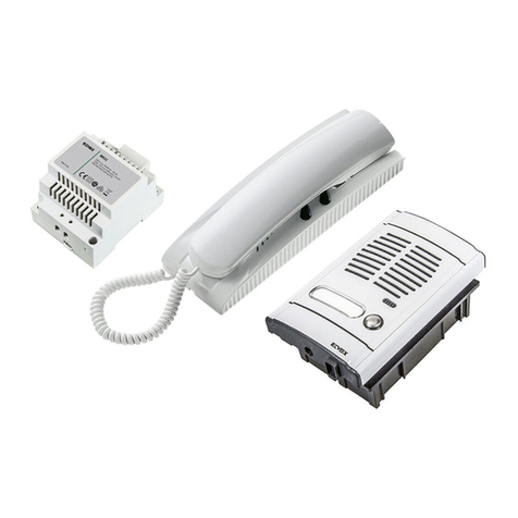
Kit citofonico bifamiliare
Two-family interphone kit
Kit poste 2 usag.
Zweifamilienhaus-Türsprechanlage set
Kit portero autom. bifamiliar
Kit porteiro autom. bifamiliar
2
ITENFRDEESPT
DESCRIZIONE IMPIANTO
DI PORTIERE ELETTRICO
UNIFILARE “1+n”
Questo tipo di impianto si avvale del
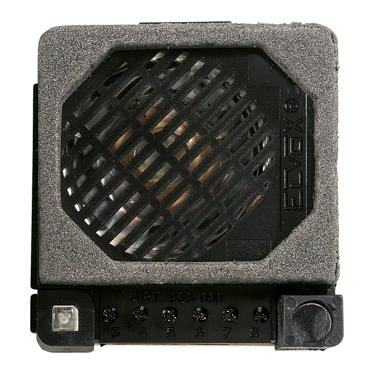
nuovo posto esterno Art. 930D che è in
grado di generare una nota elettronica
modulata per la chiamata dal posto ester-
no: in questo caso i citofoni utilizzati sono
muniti di un altoparlante per la diffusione
del suono. Il collegamento complessivo
si ottiene utilizzando un semplice trasfor-
matore che alimenta l’intero impianto.
Questo tipo di sistema è particolarmente
indicato per ristrutturazioni o conversioni
di impianti da semplice campanello a cito-
fono in quanto il collegamento del mon-
tante si effettua con un solo filo comune
più un filo di ritorno per ogni apparecchio.
Gli impianti si possono realizzare senza
segreto di conversazione (con citofoni
Art. 8877, Art. 6201) o con segreto di con-
versazione (con citofoni Art. 8873, Art.
6201+7155): in quest’ultimo caso solo
l’utente chiamato è abilitato alla conver-
sazione con il posto esterno e quindi tutti
gli altri interni rimangono esclusi. Per
un buon funzionamento dell’impianto si
consiglia di eseguire i collegamenti come
mostra lo schema di principio.
PRINCIPIO DI FUNZIONAMENTO
Quando un visitatore preme un pulsante
della targa esterna si sente nel citofono
un segnale sonoro:
l’utente interno può sollevare il microtele-
fono e conversare con il visitatore senza
limiti di tempo.
Il tempo di attivazione della serratura è
regolabile da 1 a 4 secondi tramite l’appo-
sito trimmer (P1).
DESCRIPTION INSTALLATION
POUR PORTIER ÉLECTRIQUE
AVEC UN FIL “1+n”
Ce type d’installation est équipé du
nouveau poste extérieur Art. 930D qui
est en mesure d’émettre une note élec-
tronique modulée pour l’appel depuis le
poste extérieur: dans ce cas, les postes
d’appartement utilisés sont munis d’un
haut-parleur pour la diffusion du son.
Le branchement général s’effectue en
utilisant un simple transformateur qui ali-
mente toute l’installation. Ce type de sys-
tème est particulièrement indiqué pour les
restructurations ou les conversions d’in-
stallations de simples sonnettes à postes
d’appartement, car le branchement du
montant s’effectue au moyen d’un seul
fil commun plus un fil de retour pour
chaque appareil. Les installations peu-
vent être réalisées sans secret de con-
versation (avec des postes d’appartement
Art. 8877, Art. 6201) ou avec secret de
conversation entre deux utilisateurs (avec
des postes d’appartement Art. 8873, Art.
6201+7155): dans ce dernier cas, seul
l’utilisateur appelé est habilité à la conver-
sation avec le poste extérieur, les autres
postes intérieurs étant par conséquent
exclus. Pour un bon fonctionnement de
l’installation on conseille d’effectuer les
connexions selon le schéma de base.
PRINCIPE DE FONCTIONNEMENT
Lorsqu’un visiteur appuie sur une touche
de la plaque extérieure, on entend dans
le poste un signal sonore : l’utilisateur
intérieur peut soulever le micro-combiné
et converser avec le visiteur sans limite
de temps.
Le temps d’activation de la gâche est
réglable entre 1 et 4 secondes à l’aide du
trimmer prévu à cet effet (P1).
SYSTEM DESCRIPTION OF
“1+n-WIRE” AUDIO DOOR
ENTRY SYSTEM
This type of unit makes use of the new
external unit (Art. 930D) which can gene-
rate a modulated electronic signal for a
call from the external unit; in this case,
the door phones used are supplied with
a loudspeaker for the transmission of the
sound. The overall connections are made
using a simple transformer which supplies
the whole system. This type of system
is particularly suitable for refurbishments
or conversions of systems with a simple
doorbell with loudspeaker since connec-
tion of the unit is made with a single
shared cable plus a return cable for each
unit. The systems can be fitted without a
conversation privacy function (with door
phones Art. 8877, Art. 6201) or with a
conversation privacy function between
the user and the person receiving the
call (with door phones Art. Art. 8873, Art.
6201+7155). In this latter case, only the
user called can speak with the external
unit, all the others being excluded. For a
good installation operation it is advisable
to carry out connections according to the
standard diagram.
OPERATING INSTRUCTIONS
When a visitor presses a button on the
external plaque, he will hear a sound on
the phone; the user within the building
can lift the door phone and speak to the
visitor without any time limit. The period
the lock is to be activated can be set at
anything between 1 and 4 seconds using
the special trimmer (P1).
3
PTESDEFRENIT
DESCRIÇÃO DA INSTALAÇÃO
PARA PORTEIRO ELÉCTRICO
UNIFILAR “1+n”
Este tipo de instalação serve-se do
novo posto externo Art. 930D que tem
a possibilidade produzir m toque elec-
trónico modulado para a chamada do
posto externo: neste caso os telefones
utilizados estão equipados com um alti-
falante para a difusão do som. A ligação
obtém-se utilizando o tranformador que
alimenta toda a instalação. Este tipo de
sistema é indicado, especialmente, para
restruturações ou conversöes de insta-
lações com uma campainha por telefone
em que a ligação da coluna montante
se efectua com um condutor comum
mais um de retorno por cada aparelho.
As instalaçöes podem-se executar sem
segredo de conversação (com telefones
Art. 8877, Art. 6201) ou com segredo de
conversação (com telefones Art. 8873,
Art. 6201+7155): neste último caso, sö
o utente chamado tem a possibilidade
de conversar com o posto externo e
também todos os outros utentes internos
prermancem excluídos. Para um bom
funcionamento da instalação aconselha-
-se efectuar as ligações como mostra o
esquema de princípio.
PRINCIPÍO DE FUNCIONAMENTO
Quando um visitante prime o botáo da
botoneria externa, ouve no telefone um
sinal sonoro: o utente interno pode levan-
tar o telefone e conversar com o visitante
sem limite de tempo. O tempo de activa-
ção do trinco é regulavel de 1 a 4 segun-
dos através dum potenciómetro (P1).
DESCRIPCIÓN INSTALACIÓN
PARA PORTERO ELÉCTRICO
CON DOS HILOS (1+n)
Este tipo de instalación utiliza el nuevo
aparato externo Art. 930D que puede
generar una nota electrónica modulada
para la llamada del aparato externo: de
este modo los interfonos utilizados son
provistos de un altavoz para la difusión
del sonido. El conexionado total se obtie-
ne utilizando un simple transformador que
alimenta la instalación intera. Este tipo di
sistema es particolarmente indicado para
re-estructurar o convertir instalaciones de
simple timbre a interfono pues el cone-
xionado del montante se efectúa con un
solo hilo común más un hilo de retorno
por cada aparato. Las instalaciones se
pueden realizar sin secreto de conversa-
ción (con interfonos Art. 8877, Art. 6201)
o con secreto de conversación entre un
usuario y otro (con interfonos Art. 8873,
Art. 6201+7155): en este último caso el
usuario llamado viene abilitado a la con-
versación con el aparato externo y por lo
tanto todos los otros internos permanecen
excluidos.Para un buen funcionamiento
de la instalación se aconseja de ejecutar
las conexiones como muestra el esquema
de principio.
PRINCIPIO DE
FUNCIONAMIENTO
Cuando un visitador presiona un pulsa-
dor de la placas externa se oye en el
interfono una señal sonora: el usuario
interno puede descolgar el microteléfono
y conversar con il visitador sin límites de
tiempo.
El tiempo de activación de la cerradura es
regulable de 1 a 4 segundos por medio
del trimmer apropiado (P1).
BESCHREIBUNG DER
ANLAGE FÜR “1+n DRAHT”
TÜRSPRECHANLAGE
Für diese Art Anlage wird die neue
externe Sprechstelle verwendet, die
in der Lage ist, eine modulierte elek-
tronische Note für den Ruf von der
externen Sprechstelle zu erzeugen:
in diesem Fall sind die verwendeten
Haustelefonen mit einem Lautsprecher
für die Schalldiffusion ausgestattet. Der
Gesamtanschluß wird durch Verwendung
eines einfachen Transformators erzielt,
der die ganze Anlage versorgt. Diese
Art System eignet sich insbesondere für
Umbauten oder für die Umwandlung ein-
facher Klingelanlagen in Sprechanlagen,
da der Anschluß der Anschlußsäule mit
nur einer gemeinsamen Leitung und
einer Rückleitung pro Gerät erfolgt. Die
Anlagen können ohne Mithörsperre (mit
Haustelefonen Art. 8877, Art. 6201) oder
mit Mithörsperre (mit Haustelefonen Art.
Art. 8873, Art. 6201+7155) zwischen
den Teilnehmern realisiert werden: in
letzterem Fall ist die Konversation mit
der externen Sprechstelle nur für den
angerufenen Teilnehmer möglich, und
alle anderen Innenstellen bleiben daher
von der Konversation ausgeschlossen.
Für einen optimalen Installationbetrieb
empfiehlt man die Anschlüße nach den
Prinzipschaltplan durchzufüren.
FUNKTIONSWEISE
Wenn ein Besucher auf einen Knopf
des externen Klingeltableaus drückt,
ertönt im Haustelefon ein akustisches
Signal; der interne Teilnehmer kann
den Hörer abnehmen und zeitlich unbe-
grenzt mit dem Besucher sprechen. Die
Aktivierungszeit der Sperre kann mit
einem Trimmer (P1) zwischen 1 und 4
Sekunden reguliert werden.
4
ITENFRDEESPT
P1
C
D
-
+
P2
1
2
3
4
5
6
N. c3680bR1
Schema collegamento portiere elettrico bifamiliare kit 885B
Wiring diagram for electric door-opener system for double residence kit 885B
Schéma des connexions portier électrique pour villa avec deux appartements kit 885B
Schaltplan für Zweifamilienhaus-Türsprechanlage Set 885B
Esquema de conexionado portero eléctrico bifamiliar kit 885B
Esquema de ligação do porteiro eléctrico bifamiliar kit 885B
Rete-Mains
Réseau-Netz
Red-Rede
Ripetitore di chiamata
Call repeater
Répétiteur d’appel
Lautsprecher für Rufverdoppelung
Repetidor de llamada
Repetidor de chamada
Art. 2/841
Citofono-Phone
Poste-Haustelefon
Interfono-Telefone
Art. 8877
Trasformatore
Transformer
Transformateur
Transformator
Transformador
Art. M832
Citofono-Phone
Poste-Haustelefon
Interfono-Telefone
Art. 8877
A - TARGA ART. 88T2
B- POSTO ESTERNO ART. 930D
C- PULSANTE SUPPLEMENTARE SERRATURA
D - SERRATURA ELETTRICA 12V~
E - PULSANTI
A - ENTRANCE PANEL ART. 88T2
B- SPEECH UNIT ART. 930D
C - ADDITIONAL PUSH-BUTTON FOR LOCK
D - 12V A.C. ELECTRIC LOCK
E - PUSH-BUTTONS
A - PLAQUE DE RUE ART. 88T2
B - POSTE EXTERNE ART. 930D
C - POUSSOIR SUPPLÉMENTAIRE GÂCHE
D - GÂCHE ÉLECTRIQUE 12V C.A.
E - POUSSOIRS
A - TÜRSPRECHSTELLE ART. 88T2
B - AUSSENSTELLE ART. 930D
C - ZÜZATZTLICHE TÜRÖFFNERTASTE
D - ELEKTRISCHER TÜRÖFFNER 12V~
E - TASTEN
A - PLACA ART. 88T2
B - APARATO EXTERNO ART. 930D
C - PULSADOR SUPLEMENTARIO CERRADURA
D - CERRADURA ELÉCTRICA 12V~
E - PULSADORES
A - BOTONEIRA ART. 88T2
B - POSTO EXTERNO ART. 930D
C - BOTÃO SUPLEMENTAR DE TRINCO
D - TRINCO ELÉCTRICO 12V~
E - BOTÕES
I cavi di alimentazione (230V) e i cavi
12 o 15 Vca vanno su canalizzazioni
separate dagli altri conduttori per non
determinare disturbi di induzione.
I cavi 12 o 15 Vca vanno collegati
direttamente ai morsetti 3 e 6 del posto
esterno Art. 930D.
The power supply cables (230 V) and
the 12 or 15 Vac cables should run
through separate ducts from the other
conductors, so as not to cause interfer-
ence by induction.
The 12 or 15 Vac cables should be
connected directly to the terminals 3
and 6 on the speech unit Art. 930D.
Les câbles d’alimentation (230 V) et
les câbles de 12 ou 15 Vca vont sur
des conduites séparées des autres
conducteurs pour éviter des phéno-
mènes d’induction.
Les câbles de 12 ou 15 Vca doivent
être reliés directement aux bornes 3
et 6 du micro haut-parleur Art. 930D.
Die Versorgungskabel (230V) und die
12 bzw. 15 Vac Kabel sind in von
anderen Leitern separaten Kanälen
zu verlegen, um Störungen durch
Induktionsströme vorzubeugen.
Die 12 bzw. 15 Vca Kabel sind
direkt an die Klemmen 3 und 6 der
Außenstelle Art. 930D anzuschließen.
Los cables de alimentación (230 V)
y los cables de 12 o 15 Vca deben
instalarse en canaletas separadas de
los demás conductores para evitar
interferencias por inducción.
Los cables de 12 o 15 Vca deben
conectarse directamente a los bornes
3 y 6 del aparato externo Art. 930D.
Os cabos de alimentação (230V) e
os cabos de 12 ou 15 Vca vão para
canalizações separadas dos outros
condutores para não determinar dis-
túrbios de indução.
Os cabos de 12 ou 15 Vca são direc-
tamente ligados aos bornes 3 e 6 do
posto externo Art. 930D.
C
B
120
PRI
*
G
CH 3
A
1
6
3
2
1
4
5
6
3
D
EH
2
6
3
5
5
PTESDEFRENIT
Sezione conduttori - Conductor section - Sections des conducteurs
Leiterquerchnitt - Secciones conductores - Secção condutores
Conduttori-Conductors Ø fino a 50m - Ø up to 50m Ø fino a 100m - Ø up to 100m Ø fino a 200m - Ø up to 200m
Conductors-Leitungslänge Ø jusqu’à 50m - Ø bis 50m Ø jusqu’à 100m - Ø bis 100m Ø jusqu’à 200m - Ø bis 200m
Conductores-Condutores Øhasta 50m - Ø até 50m Ø hasta 100m - Øaté 100m Ø hasta 200m - Ø até 200m
Comune (3)
Common (3)
Commun (3)
Gemeinsame (3) 0,5 mm20,75 mm21,5 mm2
Común (3)
Commun (3)
0 - 12 0,25 mm20,5 mm21 mm2
1 Fissare la vite superiore (A) nella scatola incasso (o tassello)
lasciando sporgere la testa della vite per 2-3 mm.
2 Agganciare il citofono alla vite superiore utilizzando l’apposito
foro posteriore accostandolo alla parete e tirandolo verso il
basso in direzione delle frecce.
3 Completare il fissaggio con la vite inferiore (B) nell’apposito
foro.
1 Partially fasten upper screw “A” to back box leaving it out for
2 or 3 mm.
2 Hook interphone to upper screw “A” in rear hole and pull it
downwards.
3 Complete mounting with lower screw “B” in prepared hole.
1 Fixer la vis supérieure (A) dans la boîte de raccordement (ou
vis à goujon) en laissant saillir la tête de la vis pour 2-3 mm.
2 Accrocher le poste à la vis supérieure en utilisant le trou ap-
proprié, le rapprocher à la paroi et en le tirant vers le bas en
suivant la direction des flèches.
3 Completer le montage avec la vis inférieure (B) fixée dans le
trou approprié.
1 Die obere Schraube (A) am Unterputz-Gehäuse (oder Dübel)
befestigen. Die Schraube 2-3 mm vorstehen lassen.
2 Das Haustelefon an der Schraube (A) durch das rückseitige
Lock zuhacken und es nach unten laut dem Zeichen ziehen.
3 Die untere Schraube (B) im bestimmten Loch befestigen.
1 Fijar el tornillo superior (A) en la caja empotrada (o taco) de-
jando la cabeza del tornillo unos 2-3 mm fuera.
2 Enganchar el teléfono al tornillo superior utilizando el corres-
pondiente orificio posterior; acercarlo a la pared y tirar de él
hacia abajo en la dirección ilustradas por las flechas.
3 Completar la fijación con el tornillo inferior (B) en el corres-
pondiente orificio.
1 Fixar o parafuso superior (A) no local de encaixe deixando a
cabeça do parafuso saliente 2 a 3 mm.
2 Prender o telefone ao parafuso superior, utilizando o furo
posterior adequado, aproximando-o da parede e puxando-o
para baixo na direcção da seta.
3 Completar a fixação com o parafuso (B) no furo apropriado.
INSTALLAZIONE DEL CITOFONO - PHONE INSTALLATION - INSTALLATION DU POSTE
HAUSTELEFON INSTALLIERUNG - INSTALACION DO TELÉFONO- INSTALAÇÃO DO TELEFONE
Per aprire il citofono
To open interphone
Pour ouvrir le poste
Öffnen des Haustelefone
Para abrir el teléfono
Para abrir o telefono
A
B
6
ITENFRDEESPT
Montare la targa esterna su scatola rettangolare o con tasselli.
Fix door panel on rectangular box or with expansion screws.
Installer la plaque de rue sur boîte rectangulaire ou avec vis à goujouns.
Klingeltableau an der Wand mit Schrauben und Dübel montieren.
Montar la tarjeta externa sobre la caja rectangular o con cuñas.
Montar a botoneira através de parafusos.
INSTALLAZIONE DELLE TARGHE - MOUNTING INSTRUCTIONS OF ENTRANCE PANEL
INSTALLATION DE LA PLAQUE DE RUE - MONTAGEHINWEISE FÜR TÜRSPRECHSTELLE
INSTALACION DE LA PLACA EXTERNA - INSTALAÇÃO DA BOTONEIRA EXTERIOR
Posizionamento del microfono
Positioning of the microphone
Mise en place du microphone
Einordnung des Mikrofons
Colocación del micrófono
Colocação do microfone
Per accedere al cartellino portanomi togliere il fermacartellino dal
retro come mostra la figura.
To reach name-tag, remove name-tag holder from the back, as
shown.
Pour acceder à l’étiquette porte-noms enlever le porte-étiquette de
la partie postérieure comme le montre la figure.
Um das Namensschild zu erhalten, entfernen Sie die
Namenschildhalterung von der Rückseite, wie dezeigt.
Para acceder a la tarjetita portanombres mover el sujetatarjetita
desde atrás como muestra la figura.
Para ter acesso ao cartão porta-nomes extrair a tampa de plástico
que o prende como mostra a figura.
ESTRAZIONE DEL CARTELLINO PORTANOME-NAME - TAG REMOVING
EXTRACTION DE L’ÉTIQUETTE PORTE - NOMS-HERAUSZIEHEN DES NAMENSSCHIELD
ESTRACCIÓN DE LA TARJETITA PORTANOMES - EXTRAÇÃO DO CARTÃO PORTA-NOMES
7
PTESDEFRENIT
Morsettiera
Terminal block
Boîte de raccordement
Klemmenleiste
Regleta conexiones
Bornes
Microfono
Microphone
Kikrofon
Micrófono
Microfone
Altoparlante
Loudspeaker
Haut-parleur
Lautsprecher
Altavoz
Altifalante
Volume interno
Internal volume
Volume intérieur
Lautstärke innen
Volumen interno
Volume interno
Volume esterno
External volume
Volume extérieur
Lautstärke außen
Volumen externo
Volume externo
Quando si utilizza il posto esterno 930D e si richieda di aumentare notevolmente il volume
è possibile allontanare il microfono dall’altoparlante per evitare l’effetto LARSEN (fischio).
Per spostare il microfono eseguire quanto segue:
- Aprire lo sportello con la freccia dell’Art. 930D (Fig. 1)
- Sfilare il microfono dalla sue sede.
- Inserire il microfono nel lato destro della testata inferiore del telaio serie 8000. Nella testata
sono ricavate due lamelle dove inserire il microfono (Fig. 2).
When the speech unit Art. 930D is used and the volume is to be increased considerably it
is possible to install the microphone far away from the lousdspeaker to avoid the LARSEN
effect (buzzing sound). To displace the microphone operate as it follows:
- Open the door with the arrow of Art. 930D (Fig. 1)
- Remove the microphone from its seat.
- Insert the microphone on the right hand side of the frame 8000 lower head. On the head
there are two locks where to insert the microphone (Fig. 2).
Lorqu’on utilise le poste externe Art. 930D et lorsqu’on demande d’augmenter considérable-
ment le volume il est possible d’éloigner le microphone du haut-parleur pour éviter l’effet
LARSEN (bourdonnement). Pour déplacer le microphone effectuer les opérations suivantes :
- Ouvrir la porte avec la flèche de l’Art. 930D (Fig. 1).
- Défiler le microphone de son siège.
- Insérer le microphone dans le côté droit de la tête inférieure du châssis série 8000. Dans
la tête il y a deux lamelles où insérer le microphone (Fig. 2).
Wenn die Aussenstelle Art. 930D und das Lautstärke ist beträchtlich zu verhöhen, kann das
Microfon weit vern vom Lausprecher eingebaut werden um den LARSEN Effekt (Pfeifen)
zu vermeiden.
- Die Tür mit den Pfeil des Arts. 930D öffnen (Fig. 1).
- Das Mikrofon aus seinem Sitz ausziehen
- Das Mikrofon auf die Rechtenseite des Untererkopfs des Rahmens Baureihe 8000 einste-
cken. Es sind zwei Lamellen auf dem Kopf um das Microfon einzustellen (Fig. 2).
Cuando se utiliza el aparato externo Art. 930D y hay que aumentar notablemente el volumen
se puede instalar el micrófono lejos del altavoz para evitar el efecto LARSEN (silbido). Par
desplazar el micrófono efectuar las siguients operaciones:
- Abrir la puerta con la flecha del Art. 930D (Fig. 1).
- Desfilar el micrófono de su asiento.
- Insertar el micrófono en el lado derecho de la cabeza del marco serie 8000. En la cabeza
se encuentran dos laminillas donde insertar el micrófono (Fig. 2).
Nos casos em que se utiliza o posto externo 930D e é necessário aumentar o volume, é
possível afastar o microfone do altifalante para evitar o efeito LARSEN (ruído).Para afastar
o microfone proceder do seguinte modo:
- Abrir a tampa do Art. 930D (Fig. 1), de acordo com a seta.
- Retirar o microfone da sua sede.
- Inserir o microfone no lado direito do topo inferior do caixilho série 8000. Neste topo exis-
tem duas tiras para aplicar o microfone (Fig. 2).
Regolazione tempo serratura
Lock timing setting
Réglage temps gâche
Einstellung der Sperrzeit
Regulaciones tiempo cerradura
Regulação do tempo de actuação do trinco
Fig. 1
Fig. 2
8
ITENFRDEESPT
INSTALLAZIONE DEGLI ALIMENTATORI - POWER SUPPLY INSTALLATION
INSTALLATION DES ALIMENTATIONS - INSTALLATION DER NETZGERÄTE
INSTALACIÓN DE LOS ALIMENTADORES - INSTALACIÓN DE LOS ALIMENTADORES
Caratteristiche Art. M832
Temporizzazione (cicli) e carico:
Morsetti: 12/0: 12V a.c. 0,8A continua +
1A intermittente 30 sec. ON 150 sec OFF
P = 35VA alimentazione 230V a.c. (altre
tensioni su richiesta) 50-60Hz
PRI: Protezione tramite PTC
Attenzione: Per ripristinare l’apparecchio
dopo un sovraccarico togliere la tensione
di rete per 3 minuti.
Installazione
L’alimentatore andrà posto in un luogo
asciutto e lontano da polvere e fonti di
calore.
Al fine di facilitare controlli e messe a
punto curare che il luogo sia facilmente
accessibile.
Fissare a parete l’alimentatore mediante
i tasselli in dotazione o inserendolo in
apposito quadro con barra DIN ad omega.
Features Art. M832
Timing (cycles) and load:
Terminals: 12/0: 12V a.c. 0,8A contin-
uous + 1A intermittent 30 sec. ON 150
sec. OFF
P = 35VA supply voltage 230V a.c. (other
voltages upon request) 50-60 Hz
PRI: Protection by PTC
Warning: Cut off mains supply for 3
minutes to reset the device after an over-
loading.
Installation
The power supply must be installed in a
dry place away from direct heat or dust.
Ensure easy access for inspection and
maintenance.
Secure the unit to the wall with the anchor
bolts provided or insert it into a rack with a
omega DIN bar.
Caractéristiques Art. M832
Temporisation (cycles) et charge:
Bornes: 12/0: 12V a.c. 0,8A continu + 1A
intermittent 30 sec. ON 150 sec. OFF
P = 35VA alimentation 230V a.c. (d’autres
tensions sur demande) 50-60 Hz
PRI: Protection avec PTC
Attention: Afin de mettre en fonction l’ap-
pareil de nouveau après une surcharge,
enlever la tension pendant 3 minutes.
Installation
L’alimentation devra être placée dans un
endroit sec, à l’abri de la poussière et loin
de toute source de chaleur.
An de faciliter les contrôles et les mises
au point, choisir un endroit facilement ac-
cessible.
Fixer l’alimentation sur le mur à l’aide des
chevilles fournies de série ou en l’insérant
dans un tableau approprié avec barre DIN
en oméga.
REGOLE DI INSTALLAZIONE.
L’installazione deve essere effettuata con
l’osservanza delle disposizioni regolanti
l’installazione del materiale elettrico in
vigore nel Paese dove i prodotti sono in-
stallati.
Garantire delle distanze minime attorno
all’apparecchio in modo che vi sia una
sufciente ventilazione.
L’apparecchio non deve essere sottoposto
a stillicidio o a spruzzi d’acqua.
ATTENZIONE: Per evitare di ferirsi , l’ap-
parecchio deve essere assicurato alla pa-
rete secondo quanto indicato nelle istru-
zioni di installazione.
A monte dell’alimentatore, deve essere
installato un interruttore di tipo bipolare fa-
cilmente accessibile con separazione tra i
contatti di almeno 3 mm.
CONFORMITÀ NORMATIVA.
Direttiva BT
Direttiva EMC
Norme EN 60065, EN 61000-6-1, EN
61000-6-3.
Gli alimentatori costituiscono una sor-
gente SELV rispettando i requisiti previsti
dall’articolo 411.1.2.2 della norma CEI
64-8 (2012).
La produzione del trasformatore è sotto
costante sorveglianza:
DVE
INSTALLATION RULES.
Installation should be carried out observ-
ing current installation regulations for
electrical systems in the Country where
the products are installed.
Ensure clearance around the appliance so
there is sufcient ventilation.
There must be no dripping or splashes of
water on the appliance.
WARNING: To prevent injury, the appli-
ance must be secured to the wall as de-
scribed in the installation instructions.
Above the power supply there must be a
bipolar circuit breaker that is easily acces-
sible with a contact gap of at least 3 mm.
CONFORMITY.
LV directive
EMC directive
Standards EN 60065, EN 61000-6-1, EN
61000-6-3.
Power supply units constitute SELV
sources in compliance with the require-
ments stipulated in Article 411.1.2.2 of CEI
standard 64-8 (2012).
Production of the transformer is subject to
costant surveillance:
DVE
RÈGLES D’INSTALLATION.
L’installation doit être effectuée dans le
respect des dispositions régulant l’installa-
tion du matériel électrique en vigueur dans
le Pays d’installation des produits.
Garantir des distances minimums autour
de l’appareil pour obtenir une ventilation
sufsante.
L’appareil ne doit pas être soumis à un
suintement ou des éclabous sures d’eau.
ATTENTION: Pour éviter toute blessure,
l’appareil doit être assuré au mur selon les
instructions d’installation.
En amont de l’alimentateur, installer un
interrupteur de type bipolaire facilement
accessible avec separation des contact
d’au moins 3 mm.
CONFORMITÉ AUX NORMES.
Directive BT
Directive EMC
Normes EN 60065, EN 61000-6-1, EN
61000-6-3.
Les alimentations constituent une source
SELV et respectent les qualités requises
par l’article 411.1.2.2 de la norme CEI
64-8 (2012).
La production du transformateur est sous
constante surveillance:
DVE
9
PTESDEFRENIT
Eingeschaften Art. M832
Zeitrechner (Zyklen) und Belastung:
KLemmen: 12/0: 12V a.c. 0,8A ständig
+ 1A intermittierend 30 sec. ON 150
sec. OFF
P = 35VA Versorgungsspannung 230V
a.c. (andere Spannugen auf Wunsch)
50-60 Hz
PRI: Sicherung durch PTC
Vorsicht: Um den Apparat nach einer
Überlastung wieder in Betrieb zu set-
zen, die Netzspannung für 3 Minuten
entfernen.
Installation
Das Netzgerät ist an einem trockenen
und staubfreien Ort unter Vermeidung der
Nähe von Wärmequellen zu installieren.
Zur Erleichterung von Kontrollen und Ein-
stellungen sollte der Aufstellungsort gut
zugänglich sein.
Das Netzgerät mit den beigepackten
Dübeln an der Wand befestigen oder in
einen Verteiler mit DIN-Omegaschiene
einsetzen.
INSTALLATIONSVORSCHRIFTEN.
Die Installation hat gemäß den im jewei-
ligen Verwendungsland der Produkte gel-
tenden Vorschriften zur Installation elektri-
scher Ausrüstungen zu erfolgen.
Bitte beachten Sie die vorgeschriebenen
Mindestabstände um das Gerät, um eine
ausreichende Belüftung zu gewährleisten.
Das Gerät darf weder Tropfwasser noch
Wasserspritzern ausgesetzt sein.
ACHTUNG: Zum Schutz vor Verletzungen
muss das Gerät nach den Vorgaben der
Installationsanleitungen an der Wand be-
festigt werden.
Vor dem Netzgerät ist ein leicht zugängli-
cher, zweipoliger Schalter mit Mindestab-
stand zwischen den Kontakten von 3 mm
zu installieren.
NORMKONFORMITÄT.
NS-Richtlinie
EMC-Richtlinie
Normen DIN EN 60065, EN 61000-6-1,
EN 61000-6-3.
Die Netzgeräte, die die vom Art. 411.1.2.2
der CEI 64-8 (Ausgabe 2012) Norm
Vorgesehene Fähigkeiten respektieren,
eine SELV Quelle bestellen.
Die Transformatorserzeugung ist unter
ständiger Aufsicht:
DVE
Características Art. M832
Temporización y carga:
Bornes: 12/0: 12V a.c. 0,8A continua +
1A intermitente 30 sec. ON 150 sec. OFF
P = 35VA alimentación 230V a.c. (otras
tensiones a pedido) 50-60 Hz
PRI: Protección por PTC
Attención: Para restaurar el aparato des-
pués de una sobrecarga quitar la corrien-
te durante 3 minutos.
Instalación
El alimentador tiene que ser colocado en
un lugar seco y lejos del polvo y fuentes
de calor.
Al n de facilitar controles y puestas a
punto el lugar de la instalación debe ser
fácilmente accesible.
Fijar a la pared el alimentador por medio
de tacos en dotación o insertándolo en un
cuadro apropiado con barra DIN a omega.
Características Art. M832
Temporização e carga:
Terminais: 12/0: 12V a.c. 0,8A continua +
1A intermitente 30 sec. ON 150 sec. OFF
P = 35VA alimentação 230V a.c. (outras
tensões sob pedido) 50-60 Hz
PRI: Proteção por PTC
Atenção: Para repor o aparelho após
uma sobrecarga, desligar a alimenta-
ção da rede durante 3 minutos.
Instalación
O alimentador deverá ser colocado num
local seco e ao abrigo do pó e de fontes
de calor.
Para facilitar os controlos e as anações,
certique-se de que o local é de fácil
acesso.
Fixe o alimentador à parede com as bu-
chas fornecidas ou inserindo-o num qua-
dro próprio com calha DIN tipo omega.
NORMAS DE INSTALACIÓN.
El aparato se ha de instalar en conformi-
dad con las disposiciones sobre material
eléctrico vigentes en el País.
Para garantizar una correcta ventilación
del aparato, hay que dejar un espacio
adecuado a su alrededor.
No dejar que gotas o chorros de agua mo-
jen el aparato.
ATENCIÓN: para evitar daños persona-
les, el aparato se ha de jar a la pared tal
como se describe en las instrucciones de
instalación.
Aguas arriba del alimentador se ha de
instalar un interruptor bipolar, fácilmente
accesible y con una distancia entre los
contactos de al menos 3 mm.
CONFORMIDAD NORMATIVA.
Directiva BT
Directiva EMC
Normas EN 60065 y EN 61000-6-1, EN
61000-6-3.
Los alimentadores constituyen una fuente
SELV y respectan los requisitos previstos
por el artículo 411.1.2.2 de la norma CEI
64-8 (2012).
A fabrico do transformador está sob a
constante vigilância de:
DVE
REGRAS DE INSTALAÇÃO
A instalacao deve ser efectuada de acor-
do com as disposicoes que regulam a ins-
talacao de material electrico, vigentes no
Pais em que os produtos sao instalados.
Não obstruir as aberturas ou ranhuras de
ventilação ou de dissipação de calor e não
expor o aparelho ao estilicidio du pulveri-
zação de agua.
ATENÇÃO: Para evitar ferir-se, este apa-
relho deve ser xado na parede de acordo
com as instruções de instalação.
É necessário instalar, perto da fonte de
alimentação, um interruptor apropriado,
do tipo omnipolar, com uma separação
minima de 3 mm entre os contactos.
CUMPRIMENTO DE REGULAMENTA-
ÇÃO
Directiva BT
Directiva EMC
Normas EN 60065, EN 61000-6-1, EN
61000-6-3.
Os alimentadores constituem uma fonte
SELV e cumprem os requisitos previstos
no artigo 411.1.2.2 da norma CEI 64-8
(2012).
A produção do transformador está sob
vigilância constante:
DVE
INSTALLAZIONE DEGLI ALIMENTATORI - POWER SUPPLY INSTALLATION
INSTALLATION DES ALIMENTATIONS - INSTALLATION DER NETZGERÄTE
INSTALACIÓN DE LOS ALIMENTADORES - INSTALACIÓN DE LOS ALIMENTADORES
10
ITENFRDEESPT
All’interno sollevare il microtelefono ed incominciare a parlare.
Premere l’apposito pulsante per azionare la serratura elettrica.
Answer calls by lifting phone handset. Operate electric lock by push-
ing appropriate button.
Pour répondre aux appels soulever le combiné du poste d’apparte-
ment, la gâche électrique est commandée par le bouton approprié.
Nach Abheben des Haustelefons ist die Gesprächsverbindung herg-
estellt. Türöffner durch entsprechende Taste betätigen.
En el interior, levantar el microteléfono y comenzar a hablar. Apretar
el pulsador apropiado para accionar la cerradura eléctrica.
No interior levantar o telefone e começar a falar. Premir o botão
respectivo para accionar o trinco eléctrico.
Eseguire la chiamata dall’esterno premendo il pulsante della
targa e parlare a mani libere dopo aver ricevuto la risposta.
Make calls by pushing door panel button and talk handsfree
after receiving reply.
Appeler en appuyant sur le bouton-poussoir de la plaque de rue
et parler mains libres après avoir reçu la réponse.
Herstellung des Rufes durch Betätigung des Klingeltasters.
LLamar desde el exterior apretando el pulsador de la tarjeta y
hablar a manos libres después de haber recibido la respuesta.
Efectuar a chamada do exterior premindo o botão da botoneira
e falar a mãos livres depois de receber a resposta.
USO - OPERATION - MODE D’EMPLOI - FUNKTION - UTILIZAÇÃO
11
PTESDEFRENIT
RÈGLES D’INSTALLATION.
L’installation doit être effectuée dans le respect
des dispositions régulant l’installation du maté-
riel électrique en vigueur dans le Pays d’instal-
lation des produits.
CONFORMITÉ AUX NORMES.
Directive EMC
Normes EN 61000-6-1 et EN 61000-6-3.
COMMUNICATION AUX UTILISA-
TEURS CONFORMÉMENT À LA DI-
RECTIVE 2012/19/UE (DEEE)
Pour protéger l’environnement et la
santé des personnes et éviter toute sanction
administrative, l’appareil portant ce symbole
ne devra pas être éliminé avec les ordures mé-
nagères mais devra être coné au distributeur
lors de l’achat d’un nouveau modèle. La récolte
de l’appareil portant le symbole de la poubelle
barrée devra avoir lieu conformément aux
instructions divulguées par les organisms ré-
gionaux préposés à l’élimination des déchets.
REGOLE DI INSTALLAZIONE.
L’installazione deve essere effettuata con l’os-
servanza delle disposizioni regolanti l’installa-
zione del materiale elettrico in vigore nel Paese
dove i prodotti sono installati.
CONFORMITÀ NORMATIVA.
Direttiva EMC
Norme EN 61000-6-1 e EN 61000-6-3.
INFORMAZIONE AGLI UTENTI AI
SENSI DELLA DIRETTIVA 2012/19/
UE (RAEE)
Al ne di evitare danni all’ambiente e
alla salute umana oltre che di incorrere
in sanzioni amministrative, l’apparecchiatura
che riporta questo simbolo dovrà essere smal-
tita separatamente dai riuti urbani ovvero ri-
consegnata al distributore all’atto dell’acquisto
di una nuova. La raccolta dell’apparecchiatura
contrassegnata con il simbolo del bidone bar-
rato dovrà avvenire in conformità alle istruzioni
emanate dagli enti territorialmente preposti allo
smaltimento dei riuti. Per maggiori informazio-
ni contattare il numero verde 800-862307.
INSTALLATION RULES.
Installation should be carried out observing
current installation regulations for electrical
systems in the Country where the products are
installed.
CONFORMITY.
EMC directive
Standards EN 61000-6-1 and EN 61000-6-3.
INFORMATION FOR USERS UNDER
DIRECTIVE 2012/19/UE (WEEE)
In order to avoid damage to the envi-
ronment and human health as well as
any administrative sanctions, any ap-
pliance marked with this symbol must be dis-
posed of separately from municipal waste, that
is it must be reconsigned to the dealer upon
purchase of a new one. Appliances marked
with the crossed out wheelie bin symbol must
be collected in accordance with the instructions
issued by the local authorities responsible for
waste disposal.
INSTALLATIONSVORSCHRIFTEN.
Die Installation hat gemäß den im jeweiligen
Verwendungsland der Produkte geltenden
Vorschriften zur Installation elektrischer Aus-
rüstungen zu erfolgen.
NORMKONFORMITÄT.
EMC-Richtlinie
Normen DIN EN 61000-6-1 und EN 61000-
6-3.
VERBRAUCHERINFORMATION
GEMÄSS RICHTLINIE 2012/19/UE
(WEEE)
Zum Schutz von Umwelt und Gesund-
heit, sowie um Bußgelder zu vermeiden, muss
das Gerät mit diesem Symbol getrennt vom
Hausmüll entsorgt oder bei Kauf eines Neu-
geräts dem Händler zurückgegeben werden.
Die mit dem Symbol der durchgestrichenen
Mülltonne gekennzeichneten Geräte müssen
gemäß den Vorschriften der örtlichen Behör-
den, die für die Müllentsorgung zuständig sind,
gesammelt warden.
NORMAS DE INSTALACIÓN.
El aparato se ha de instalar en conformidad
con las disposiciones sobre material eléctrico
vigentes en el País.
CONFORMIDAD NORMATIVA.
Directiva EMC
Normas EN 61000-6-1 y EN 61000-6-3.
INFORMACIÓN A LOS USUARIOS
DE CONFORMIDAD CON LA DIREC-
TIVA 2012/19/UE (RAEE)
Para evitar perjudicar el medio am-
biente y la salud de las personas, así como
posibles sanciones administrativas, el aparato
marcado con este símbolo no deberá elimi-
narse junto con los residuos urbanos y podrá
entregarse en la tienda al comprar uno nuevo.
La recogida del aparato marcado con el símbo-
lo del contendedor de basura tachado deberá
realizarse de conformidad con las instruccio-
nes emitidas por las entidades encargadas de
la eliminación de los residuos a nivel local.
REGRAS DE INSTALAÇÃO
A instalacao deve ser efectuada de acordo
com as disposicoes que regulam a instalacao
de material electrico, vigentes no Pais em que
os produtos sao instalados.
CUMPRIMENTO DE REGULAMENTAÇÃO
Directiva EMC
Normas EN 61000-6-1 e EN 61000-6-3.
INFORMAÇÃO AOS UTILIZADO-
RES NOS TERMOS DA DIRECTIVA
2012/19/UE (REEE)
Para evitar danos ao meio ambiente e
à saúde humana, e evitar incorrer em sanções
administrativas, o equipamento que apresenta
este símbolo deverá ser eliminado separata-
mente dos resíduos urbanos ou entregue ao
distribuidor aquando da aquisição de um novo.
A recolha do equipamento assinalado com o
símbolo do contentor de lixo barrado com uma
cruz deverá ser feita de acordo com as instru-
ções fornecidas pelas entidades territorialmen-
te previstas para a eliminação de resíduos.
The instruction manual is downloadable
from the site www.vimar.com
Il manuale istruzioni è scaricabile dal sito
www.vimar.com
Télécharger le manuel d’instructions sur le
site www.vimar.com
Die Bedienungsanleitung ist auf der Website
www.vimar.com zum Download verfügbar
El manual de instrucciones se puede des-
cargar en la página web www.vimar.com
É possível descarregar o manual de instru-
ções no site www.vimar.com
Vimar SpA: Viale Vicenza, 14
36063 Marostica VI - Italy
Tel. +39 0424 488 600 - Fax (Italia) 0424 488 188
Fax (Export) 0424 488 709
www.vimar.com
S6I.885.B00 06 16 02
VIMAR - Marostica - Italy

Other Vimar Intercom System manuals

Vimar ELVOX 40610.S User manual

Vimar

Vimar ELVOX 40610.S User manual

Vimar 7549 User manual

Vimar

Vimar 7549 User manual

Vimar Elvox K40912 User manual

Vimar

Vimar Elvox K40912 User manual

Vimar ELVOX K40547.E2 User guide

Vimar

Vimar ELVOX K40547.E2 User guide

Vimar ELVOX 7549 User manual

Vimar

Vimar ELVOX 7549 User manual

Vimar ELVOX Pixel Series Assembly instructions

Vimar

Vimar ELVOX Pixel Series Assembly instructions

Vimar ELVOX K7559G.01 User guide

Vimar

Vimar ELVOX K7559G.01 User guide

Vimar ELVOX PIXEL UP: 40415.S User guide

Vimar

Vimar ELVOX PIXEL UP: 40415.S User guide

Vimar 8870 Series User guide

Vimar

Vimar 8870 Series User guide

Vimar ELVOX 41007 User guide

Vimar

Vimar ELVOX 41007 User guide

Vimar 6341 User manual

Vimar

Vimar 6341 User manual

Vimar Elvox 6A40 User manual

Vimar

Vimar Elvox 6A40 User manual

Vimar ELVOX 885H/S Assembly instructions

Vimar

Vimar ELVOX 885H/S Assembly instructions

Vimar ELVOX Videocitofonia 1100 User manual

Vimar

Vimar ELVOX Videocitofonia 1100 User manual

Vimar ELVOX PIXEL UP 40405 User manual

Vimar

Vimar ELVOX PIXEL UP 40405 User manual

Vimar Elvox 860A User manual

Vimar

Vimar Elvox 860A User manual

Vimar ELVOX K40980 User manual

Vimar

Vimar ELVOX K40980 User manual

Vimar Elvox 13K1 Assembly instructions

Vimar

Vimar Elvox 13K1 Assembly instructions

Vimar Elvox 7200 Series User manual

Vimar

Vimar Elvox 7200 Series User manual

Vimar Elvax 885G Assembly instructions

Vimar

Vimar Elvax 885G Assembly instructions

Vimar ELVOX TAB 7509 Assembly instructions

Vimar

Vimar ELVOX TAB 7509 Assembly instructions

Vimar Elvox 13F3 User manual

Vimar

Vimar Elvox 13F3 User manual

Vimar STEELY Series Assembly instructions

Vimar

Vimar STEELY Series Assembly instructions

Vimar ELVOX 46237.040A User manual

Vimar

Vimar ELVOX 46237.040A User manual

Popular Intercom System manuals by other brands

Clear-Com HME DX210 operating instructions

Clear-Com

Clear-Com HME DX210 operating instructions

Bitron Video GVM3000 instruction manual

Bitron Video

Bitron Video GVM3000 instruction manual

HIK VISION DS-KD8002-VM user manual

HIK VISION

HIK VISION DS-KD8002-VM user manual

Timeguard DoorCom DCEX3 Installation & operating instructions

Timeguard

Timeguard DoorCom DCEX3 Installation & operating instructions

basIP AV-04SD user manual

basIP

basIP AV-04SD user manual

Cellularline Interphone EDGE user manual

Cellularline

Cellularline Interphone EDGE user manual

Bitron Video AV1423/15 instruction manual

Bitron Video

Bitron Video AV1423/15 instruction manual

HIK VISION DS-1350HM user manual

HIK VISION

HIK VISION DS-1350HM user manual

ICRealtime VTO installation guide

ICRealtime

ICRealtime VTO installation guide

HIK VISION DS-KH9510-WTE1 Configuration guide

HIK VISION

HIK VISION DS-KH9510-WTE1 Configuration guide

ProX XV-NE user manual

ProX

ProX XV-NE user manual

HIK VISION DS-KH6320-WTDE1 Configuration guide

HIK VISION

HIK VISION DS-KH6320-WTDE1 Configuration guide

Data Video ITC-100SL instruction manual

Data Video

Data Video ITC-100SL instruction manual

HIK VISION DS-KH6320-WTDE1 manual

HIK VISION

HIK VISION DS-KH6320-WTDE1 manual

HIK VISION ADS-24S-12 1224GPCN user manual

HIK VISION

HIK VISION ADS-24S-12 1224GPCN user manual

HIK VISION DS-KIS603-P(B) user manual

HIK VISION

HIK VISION DS-KIS603-P(B) user manual

Clear-Com Eclipse HX-Median user guide

Clear-Com

Clear-Com Eclipse HX-Median user guide

basIP AV-05FD user manual

basIP

basIP AV-05FD user manual

manuals.online logo
manuals.online logoBrands
  • About & Mission
  • Contact us
  • Privacy Policy
  • Terms and Conditions

Copyright 2025 Manuals.Online. All Rights Reserved.