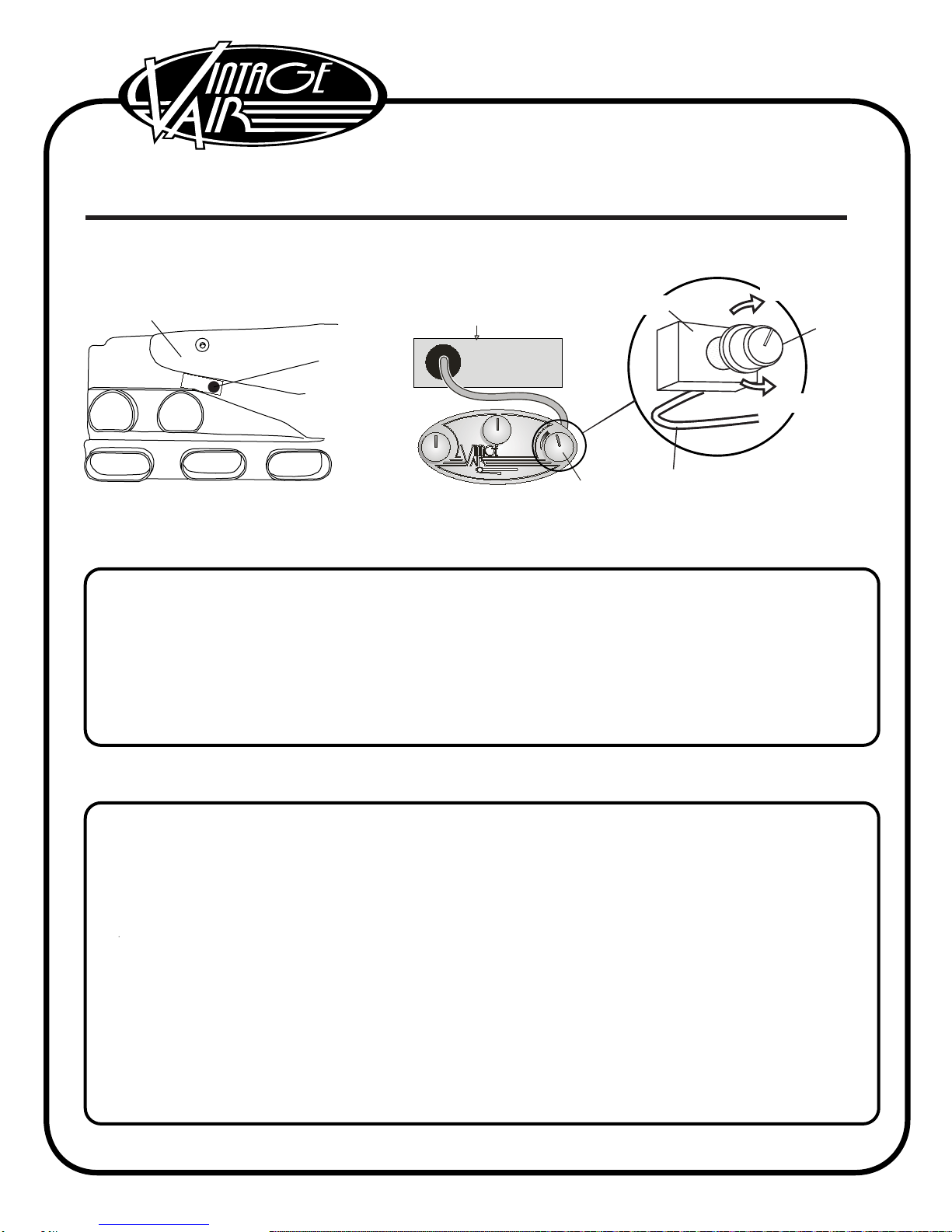
NOTE: Evaporator thermostat capillary tube must be inserted Through evaporator sub case coil.
See illustrations below. Refer to seperate instructions included with your evaporator kit to insert
the capillary tube.
This sticker is located on the
top side of the evaporator case.
Thermostat
Compact Sub case
Top View Shown
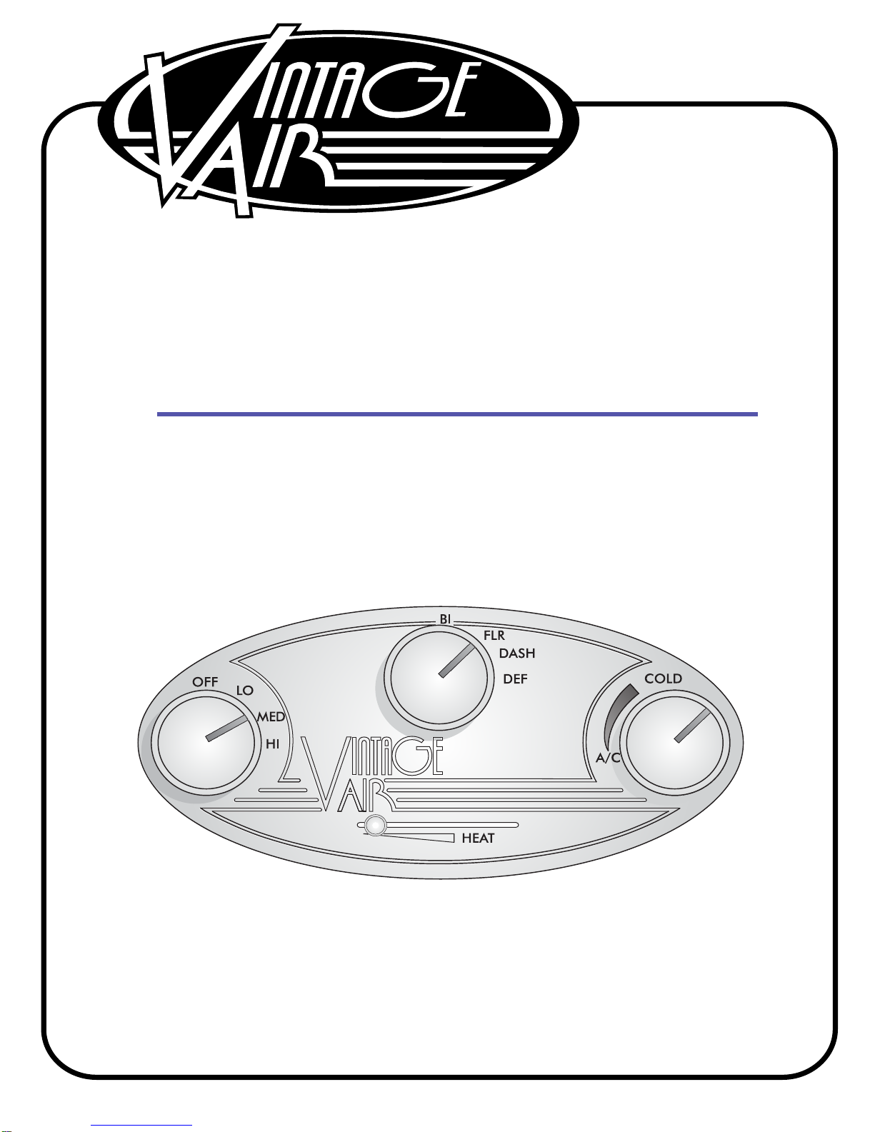
OFF COLD
LO
MED
HI
FLR
DASH
DEF
BI
HEAT
A/C
INSERT TH ERMOSTAT
CAPILL ARY TUBE
THRU THI S HOLE TH E
ENTIRE TH ICKNESS OF
EVAPO RATOR COIL.
Insert thermostat
capillary tube here
into the coil the
entire thickness.
Then carefully bring
it back out approx.
one inch
1. The air conditioner thermostat controls coil temperature. It is shipped adjusted fully cold (clockwise) and,
in the majority of cases, the A/C will operate correctly as shipped.
2. Turning the knob on the thermostat to the right (clockwise) makes the system operate colder. If the
thermostat is set too cold, the evaporator will ice up. If this happens, the evaporator coil is restricted with
ice and cold air flow will be reduced.
3. Turning the knob to the left (counterclockwise) makes the system operate warmer. The compressor
clutch will cycle off frequently and the A/C system will not get as cool as it could.
1. Symptom: The A/C works well at first, but then quits cooling. The air flow from the vents is low and the
compressor cycles infrequently.
Solution: The thermostat is set too cold and the evaporator is icing up and restricting air flow. Allow
the ice to melt and set the thermostat warmer (counter clockwise) 10% of a turn each
adjustment until the symptoms diminish.
2. Symptom: A/C never gets cold and the compressor clutch cycles frequently.
Solution: The thermostat is set too warm. Set the thermostat colder (clockwise) 10% of a turn each
adjustment until the compressor clutch cycles infrequently. Avoid setting the thermostat too
cold.
3. Symptom: The A/C never gets cold, sometimes even blows hot, and the A/C compressor clutch
infrequently cycles off.
Solution: The heater may be on at all times. Carefully feel around the heater hoses at the firewall. They
should be cold when the A/C is on. If the hoses are hot:
A) The heater control valve may be installed backwards. Check the flow direction arrow on the
valve against the illustration in your installation instructions.
B) The heater control valve is installed in wrong heater hose.
Air Conditioning Adjustments
Imporatant Notice—Please Read!
Adjusting A/C Thermostat
Adjustable
Knob
Colder
Counterclockwise
Clockwise
Warmer
Thermostat
Insert Thermostat
Capillary Tube Through
This Hole the Entire
Thickness of Evaporator
Coil.
Capillary Tube
to Evaporator
Coil