8
www.vintageair.com
903257 REV E 06/24/19, PG 8 OF 10
RED
CIRCUIT BREAKER
30 AMP
+
+
-
BLACK
RED
WHITE
RED
CHASSIS GROUND
A/C
COMPRESSOR
RELAY
Ignition Switch:
Dash Light:
NOTE:
MOUNT RELAY
IN DESIRED
LOCATION
UNDER DASH
GREEN
FIREWALL
BLUE
BLUE
RED
&
WHITE
VIOLET
(IGNITION HOT
TERMINAL)
IGNITION
SWITCH
DASH BACK LIGHT+0-12v
TAN
GRAY
BLUE
WHITE
WHITE
RED
RED
WHITE
COMPRESSOR
BATTERY
NOTE: CONNECT WHITE
WIRES DIRECTLY TO
(-) BATTERY TERMINAL
BAT
RUN
12V
RED
GREEN
RED
RED
BLUE
LATCH
BLACK
BINARY
SAFETY
SWITCH
YELLOW
ORANGE
WIRING
HARNESS
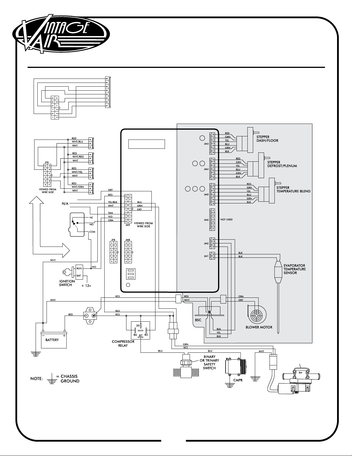
Violet 12V Ign Switch Source (Key On
Accessory) Position Must Be Switched.
When Using A Vintage Air Supplied
Control Panel, Connect The Tan Wire
From The Gen IV Evaporator Wiring
Harness To The Factory Dash Lights To
Enable Panel Backlighting.
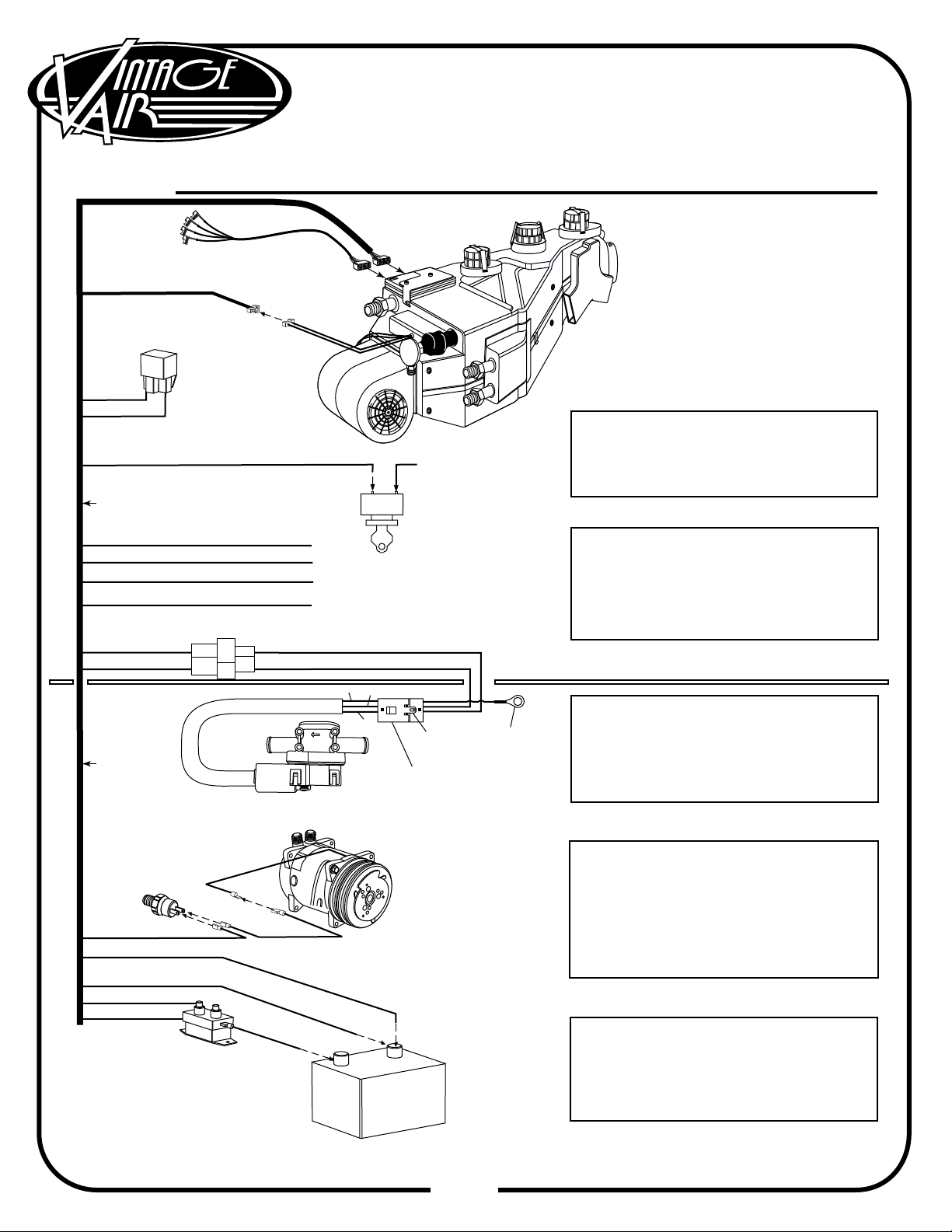
Binary: Connect As Shown (Typical
Compressor Wiring). Be Sure
Compressor Body Is Grounded.
Trinary Switch: Connect According To
Trinary Switch Wiring Diagram.
Install With Servo Motor Facing Down,
As Shown. Note Flow Direction Arrow
Molded Into Valve Body, And Install
Accordingly.
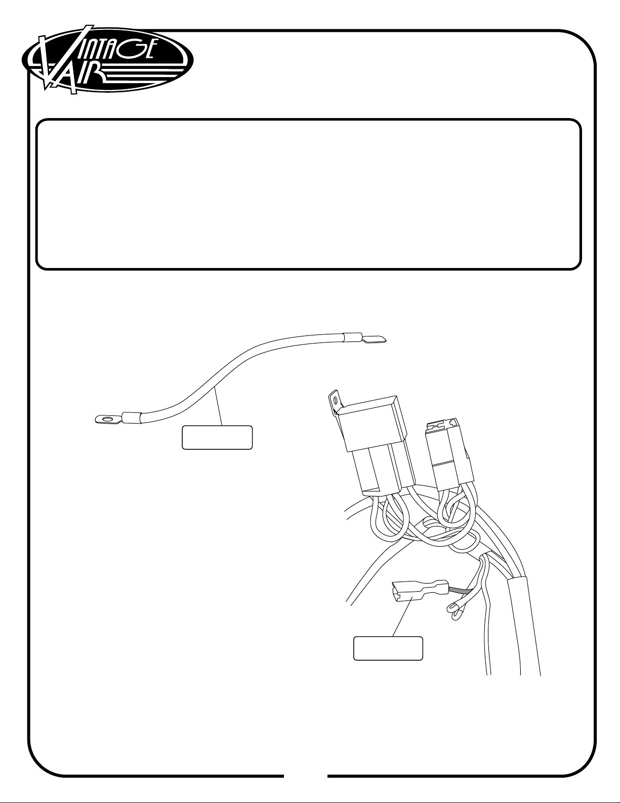
White Must Run To (-) Battery. Red May
Run To (+) Battery Or Starter. Mount
Circuit Breaker As Close to Battery As
Possible.
Heater Control Valve:
Binary/Trinary & Compressor:
Circuit Breaker/Battery:
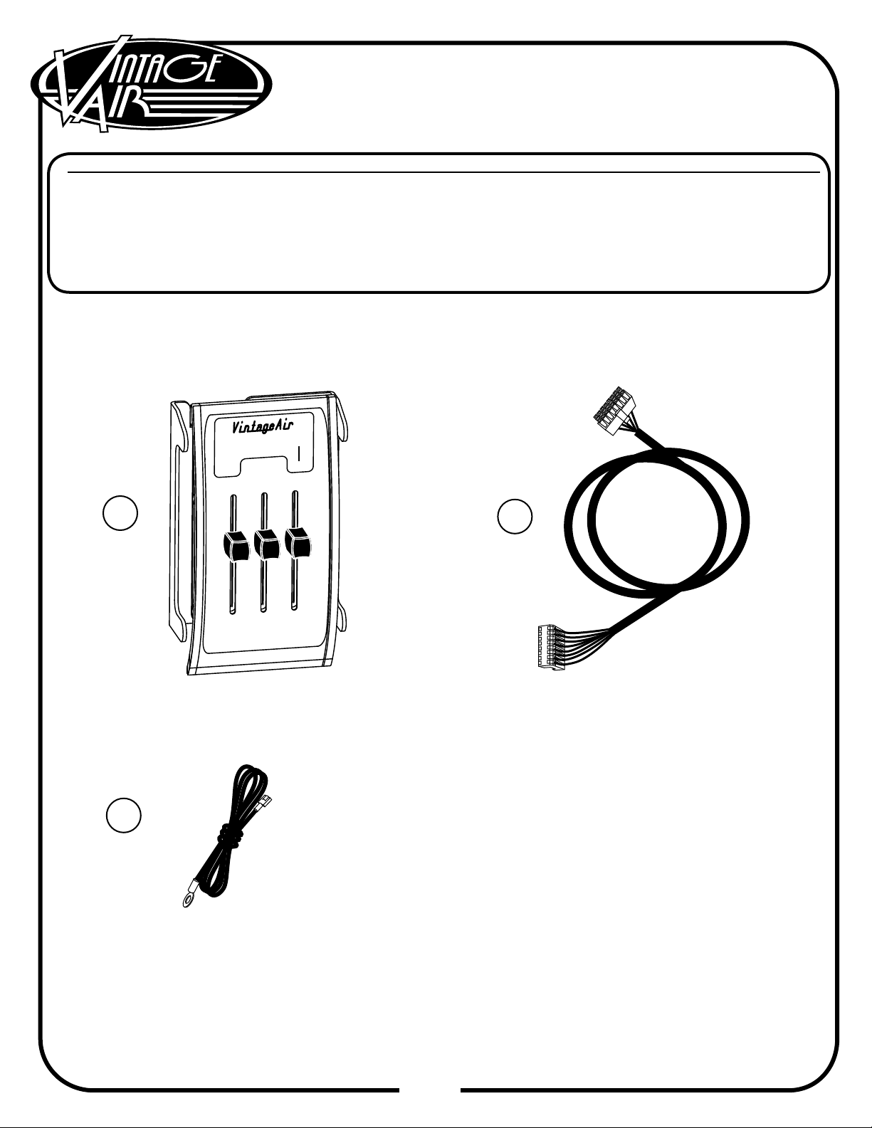
CONTROL
WIRING
HARNESS
NOTE:
YELLOW & ORANGE
COMING FROM
HARNESS ARE NOT
USED.
WIRING
HARNESS
GRAY WIRE IS USED FOR
PROGRAMING CONTROLS
IF APPLICABLE
WIRING
HARNESS
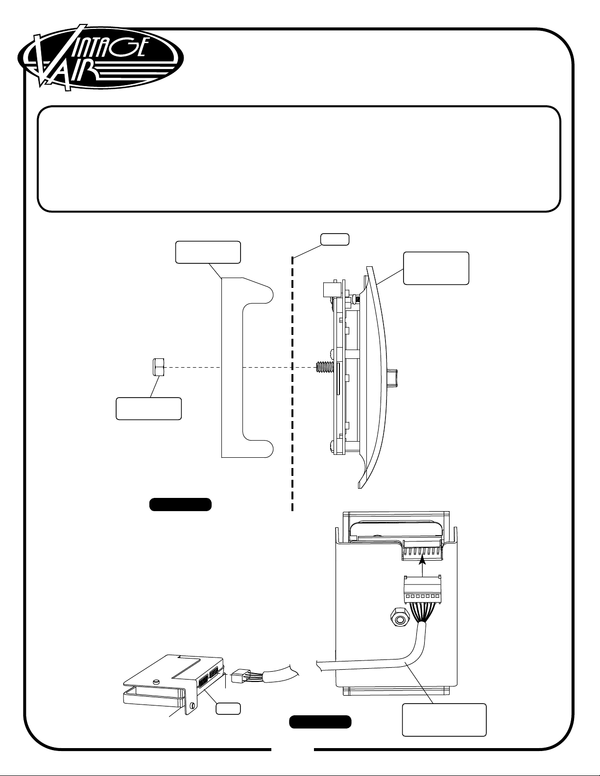
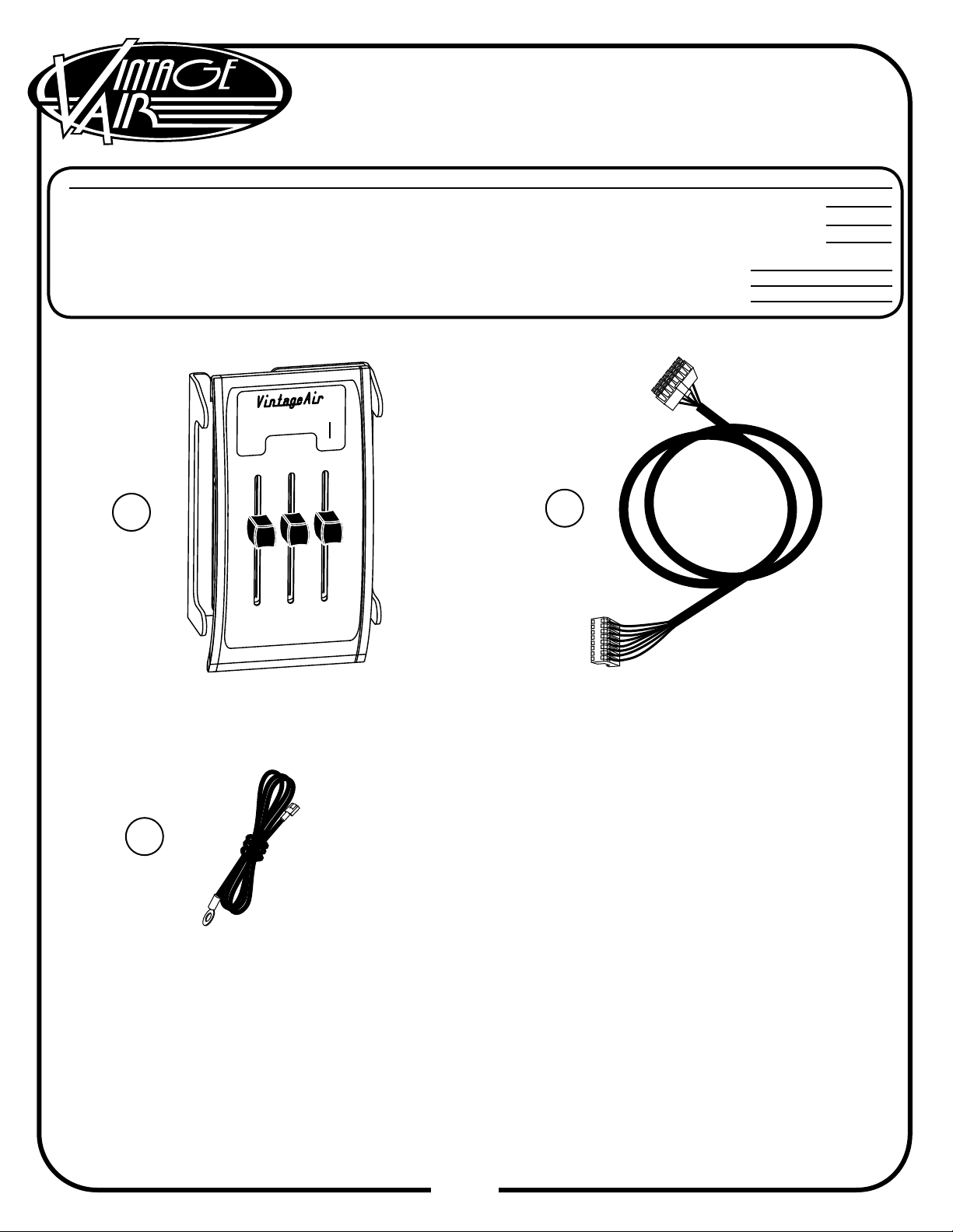
Gen IV Wiring
Connection Instruction
HEATER
CONTROL VALVE
WARNING:
ALWAYS MOUNT CIRCUIT BREAKER
AS CLOSE TO THE BATTERY AS POSSIBLE.
(NOTE: WIRE BETWEEN BATTERY AND
CIRCUIT BREAKER IS UNPROTECTED
AND SHOULD BE CAREFULLY ROUTED
TO AVOID A SHORT CIRCUIT).
NOTE: HEATER CONTROL
VALVE CONNECTION AND
CHASSIS GROUND MAY BE
LOCATED ON EITHER SIDE
OF THE FIREWALL. ENSURE
CONNECTOR IS LATCHED
FIRMLY.