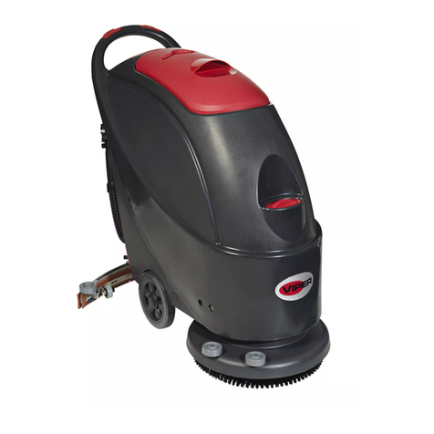
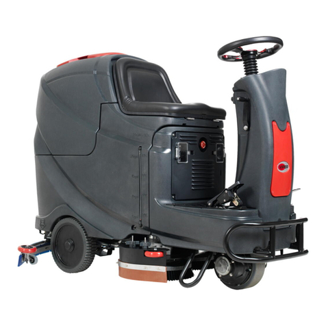
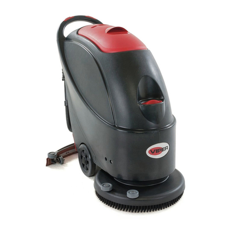
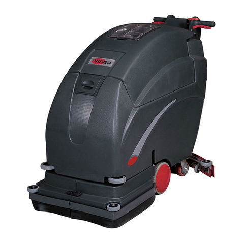
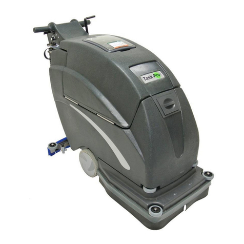
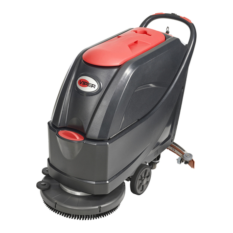
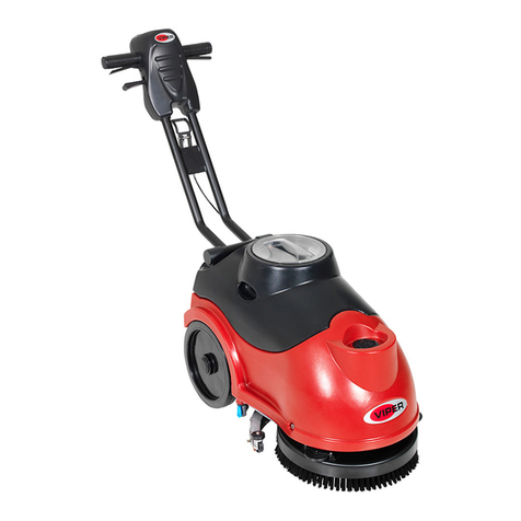
Viper 50000532 User manual

USER MANUAL
AS5160 & AS5160T / AS5160TO
AS5160 & AS5160T
AS5160TO
Company information:
www.vipercleaning.eu
VS12002-EU Rev.06
08 Oct. 2021
Model: 50000398 / 50000403 /
50000532 / 50000533 / 50000549

EU / UE / EL / EC / EE / ES / EÚ / AB
Declaration of Conformity
Prohlášení o shodě
Konformitätserklärung
Overensstemmelseserklæring
Declaración de conformidad
Vastavusdeklaratsioon
Déclaration de conformité
Vaatimustenmukaisuusvakuutus
Декларация за съответствие
Δήλωση συμμόρφωσης
Megfelelősségi nyilatkozat
Izjava o sukladnosti
Dichiarazione di conformità
Atitikties deklaracija
Atbilstības deklarācija
Samsvarserklæring
Conformiteitsverklaring
Declaração de conformidade
Deklaracja zgodności
Declaratie de conformitate
Декларация осоответствии
Försäkran om överensstämmelse
Vyhlásenie o zhode
Izjava o skladnosti
Uygunluk beyanı
Manufacturer / Výrobce / Hersteller / Fabrikant / Fabricante / Κατασκευαστής /
Gyártó / Proizvođač/ Fabbricante / Gamintojas / Ražotājs / Produsent / Fabrikant /
Fabricante / Producent / Producător / производитель / Tillverkaren / Výrobca /
Proizvajalec/ Üretici firma:
Nilfisk A/S, Kornmarksvej 1
DK-2605 Broendby, DENMARK
Product / Produkt / Producto, Toode, Produit, Tuote/ Πродукт /
Προϊόν / Termék / Proizvod / Prodotto / Produktas / Produkts /
Artikel / Produtos / Produs / Izdelek / Ürün
AS5160*, AS5160T*
Description / Popis / Beschreibung / Beskrivelse / Descripción /
Kirjeldus / La description / Kuvaus / Oписание / Περιγραφή / Leirás /
Opis / Descrizione / Aprašymas / Apraksts / Beschrijving / Descrição /
Descriere / Beskrivning / Popis / Açıklama
FC - Floor Scrubber/Sweeper - Battery
Charging mode: 100-240V 50/60Hz;
Working mode: 24V DC, IP24
We, Nilfisk hereby declare under our sole
responsibility, that the above mentioned
product(s) is/are in conformity with the following
directives and standards.
My, Nilfisk prohlašujeme na svou výlučnou
odpovědnost, že výše uvedený výrobek je ve
shodě s následujícími směrnicemi a normami.
Wir, Nilfisk erklären in alleiniger Verantwortung,
dass das oben genannte Produkt den folgenden
Richtlinien und Normen entspricht.
Vi, Nilfisk erklærer hermed under eget ansvar at
ovennævnte produkt(er) er i overensstemmelse
med følgende direktiver og standarder.
Nosotros, Nilfisk declaramos bajo nuestra única
responsabilidad que el producto antes
mencionado está en conformidad con las
siguientes directivas y normas
Meie, Nilfisk Käesolevaga kinnitame ja kanname
ainuisikulist vastutust, et eespool nimetatud toode
on kooskõlas järgmiste direktiivide ja
Nilfisk déclare sous notre seule responsabilité que
le produit mentionné ci-dessus est conforme aux
directives et normes suivantes.
Me, Nilfisk täten vakuutamme omalla vastuulla,
että edellä mainittu tuote on yhdenmukainen
seuraavien direktiivien ja standardien mukaisesti
Ние, Nilfisk Снастоящото декларираме на своя
лична отговорност, че посочените по-горе
продуктът евсъответствие със следните
директиви истандарти.
Εμείς, Nilfisk δηλώνουμε με αποκλειστική μας
ευθύνη, ότι το προαναφερόμενο προϊόν
συμμορφώνεται με τις ακόλουθες οδηγίες και
πρότυπα.
Mi, Nilfisk Kijelentjük, egyedüli felelősséggel, hogy
a fent említett termék megfelel az alábbi
irányelveknek és szabványoknak
Mi, Nilfisk Izjavljujemo pod punom odgovornošću,
da gore navedeni proizvod u skladu sa sljedećim
direktivama i standardima.
Noi, Nilfisk dichiara sotto la propria responsabilità,
che il prodotto di cui sopra è conforme alle
seguenti direttive e norme.
Mes, "Nilfisk pareiškiu vienašališkos atsakomybės,
kad pirmiau minėtas produktas atitinka šias
direktyvas ir standartus
Mēs, Nilfisk šo apliecinu ar pilnu atbildību, ka
iepriekš minētais produkts atbilst šādām
direktīvām un standartiem
Vi, Nilfisk erklærer herved under eget ansvar, at
det ovennevnte produktet er i samsvar med
følgende direktiver og standarder
We verklaren Nilfisk hierbij op eigen
verantwoordelijkheid, dat het bovengenoemde
product voldoet aan de volgende richtlijnen en
normen
Nós, a Nilfisk declaramos, sob nossa exclusiva
responsabilidade, que o produto acima
mencionado está em conformidade com as
diretrizes e normas a seguir.
My, Nilfisk Niniejszym oświadczamy z pełną
odpowiedzialnością, że wyżej wymieniony produkt
jest zgodny z następującymi dyrektywami i
normami..
Noi, Nilfisk Prin prezenta declarăm pe propria
răspundere, că produsul mai sus menționat este în
conformitate cu următoarele standarde și
directive.
Ми, Нилфиск овим изјављујем под пуном
одговорношћу, да наведеног производ је у
складу са следећим директивама и
стандардима.
Vi Nilfisk förklarar härmed under eget ansvar att
ovan nämnda produkt överensstämmer med
följande direktiv och normer.
My, Nilfisk prehlasujeme na svoju výlučnú
zodpovednosť, že vyššie uvedený výrobok je v
zhode s nasledujúcimi smernicami a normami.
Mi, Nilfisk izjavljamo s polno odgovornostjo, da je
zgoraj omenjeni izdelek v skladu z naslednjimi
smernicami in standardi.
Nilfisk, burada yer alan tüm sorumluluklarımıza
göre, yukarıda belirtilen ürünün aşağıdaki
direktifler ve standartlara uygun olduğunu beyan
ederiz.
2006/42/EC
EN 60335-1:2012+A11:2014
EN 60335-2-72:2012
2014/30/EU
EN 55014-1:2017
EN 55014-2:2015
EN 61000-3-2:2014
EN 61000-3-3 :2013
Authorized
signatory:
July 13, 2018
Lars Gjødsbøl, Executive Vice President Global
Products & Services

UK Declaration of Conformity
We,
Nilfisk Ltd
Nilfisk House, Bowerbank Way Gilwilly Industrial Estate
Penrith Cumbria
CA11 9BQ UK
Hereby declare under our sole responsibility that the
Product: FC - Floor Scrubber/Sweeper - Battery
Description: Charging mode: 100-240V 50/60Hz; Working mode: 24V DC, IP24
Type: AS5160, AS5160T, AS5160TO
Are in compliance with the following standards:
EN 60335-1:2012+A11:2014+A13:2017
EN 60335-2-72:2012
EN 55014-1:2017+A11:2020
EN 55014-2:2015
EN 61000-3-2:2014
EN 61000-3-3:2013
Following the provisions of:
Supply of Machinery (Safety) Regulations 2008/1597
Electromagnetic Compatibility Regulations 2016/1091
Penrith, 07-06-2021
Stewart Dennett
GM/MD

USER MANUAL ENGLISH
1
TABLE OF CONTENTS
INTRODUCTION .................................................................................................................................. 2
GUIDE PURPOSE AND CONTENTS........................................................................................................................... 2
HOW TO KEEP THIS GUIDE ....................................................................................................................................... 2
DECLARATION OF CONFORMITY ........................................................................................................................... 2
ACCESSORIES AND MAINTENANCE ...................................................................................................................... 2
CHANGE AND IMPROVEMENT ................................................................................................................................ 2
SCOPE OF APPLICATION ........................................................................................................................................... 2
MACHINE IDENTIFICATION DATA ......................................................................................................................... 2
TRANSPORT AND UNPACKING................................................................................................................................ 3
SAFETY .................................................................................................................................................. 3
VISIBLE SYMBOLS ON THE MACHINE ................................................................................................................... 3
SYMBOLS THAT APPEAR ON THEINSTRUCTION FOR USEMANUAL ............................................................. 3
GENERAL SAFETY INSTRUCTION ........................................................................................................................... 4
MACHINE DESCRIPTION ................................................................................................................. 6
MACHINE STRUCTURE .............................................................................................................................................. 6
CONTROL PANEL ........................................................................................................................................................ 7
DISPLAY WINDOW OF CHARGER INDICATON LIGHT ....................................................................................... 7
WIRING DIAGRAM ...................................................................................................................................................... 9
OPERATING GUIDE .......................................................................................................................... 12
BATTERY CHECK/SETTING ON A NEW MACHINE ............................................................................................ 12
BATTERY INSTALLATION AND BATTERY TYPESETTING (WET OR GEL/ AGM) ....................................... 13
ACCORDING TO THE TYPE OF BATTERIES (WET OR GEL / AGM), SET THE MACHINE ........................... 14
BRUSH/PAD-HOLDER INSTALLATION AND UNINSTALLATION .................................................................... 15
ADJUSTING THE BALANCE OF SQUEEGEE ......................................................................................................... 16
SOLUTION OR WASHING WATER TANK FILLING ............................................................................................. 16
MACHINE START AND STOP .................................................................................................................................. 16
ADJUSTING THE LEVEL OF ORBITALDECK (ONLY FOR ORBITAL MACHINE) .......................................... 17
MACHINE OPERATION (SCRUBBERING AND DRYING) ................................................................................... 17
TANK EMPTYING ...................................................................................................................................................... 18
AFTER USING THE MACHINE ................................................................................................................................. 19
MACHINE LONG INACTIVITY ................................................................................................................................ 20
FIRST PERIOD OF USE .............................................................................................................................................. 20
MAINTENANCE ................................................................................................................................. 20
SCHEDULED MAINTENANCE TABLE ................................................................................................................... 20
BATTERY CHARGING .............................................................................................................................................. 21
BRUSH/PAD CLEANING ........................................................................................................................................... 22
SOLUTION FILTER CLEANING ............................................................................................................................... 22
SQUEEGEE CLEANING ............................................................................................................................................. 23
SQUEEGEE BLADE CHECK AND REPLACEMENT .............................................................................................. 24
TANK AND VACUUM GRID WITH FLOAT CLEANING, AND COVER GASKET CHECK .............................. 25
MACHINE WORKING HOUR CHECK ..................................................................................................................... 26
FUSE CHECK/REPLACEMENT ................................................................................................................................ 26
ACCESSORIES/OPTIONS .......................................................................................................................................... 27
TROUBLESHOOTING ....................................................................................................................... 27
SCRAPPING ......................................................................................................................................... 27

USER MANUAL ENGLISH
2
INTRODUCTION
CAUTION!
Some general and detailed machine information is not included in this guide.
Please refer to Instruction for Use Manual on supplied CD-ROM reading by Adobe® Reader®.
NOTE
The numbers in brackets refer to the components shown in Machine Description chapter.
GUIDE PURPOSE AND CONTENTS
The purpose of this Quick Start Guide is to provide the operator with all basic information to use the machine proper-
ly. For information about technical characteristics, operation, machine inactivity, spare parts and safety conditions etc.,
please refer to Instruction for Use manual on supplied CD-ROM.
Before performing any procedure on the machine, the operators and qualified technicians must read the Instruction
for Use manual. Contact our company in case of doubts concerning the interpretation of the instructions or for any
further information.
HOW TO KEEP THIS GUIDE
The Quick Start Guide must be kept near the machine, inside an adequate case, away from liquids and other sub-
stances that can cause any damage to it.
DECLARATION OF CONFORMITY
Declaration of Conformity is supplied with the machine and certifies machine conformity with the law in force.
NOTE
The copies of the original declaration of conformity are provided together with the machine
documentation.
ACCESSORIES AND MAINTENANCE
All the necessary operation, maintenance and repair procedures must be made by qualified personnel, our company
appointed repair center. ONLY original or approved spare parts and accessories can be used.
Contact our company customer service for any service or purchase of accessories or spare parts if necessary.
CHANGE AND IMPROVEMENT
We committed to continuous improvement of its products, the company reserves the right to the machine changes and
improvements without informing in additional.
SCOPE OF APPLICATION
The scrubber applies to commercial and industrial use. It is suitable for cleaning smooth and solid floor, operating by
a qualified personnel in safety circumstance. It is not suitable for outdoor use or carpet or rough floor cleaning.
MACHINE IDENTIFICATION DATA
The machine serial number and model name are marked on the serial label.
This information is useful. Use the following table to write down the machine identification data when requiring
spare parts for the machine.
MACHINE MODEL
......
.........................................
..............................
MACHINE SERIAL NUMBER.....................................
......................

USER MANUAL ENGLISH
3
TRANSPORT AND UNPACKING
When the carrier delivers the machine, make sure the packaging and machine are both whole and undamaged. If any
damaged, make the carrier know the damage and before accepting the goods, reserve the right in compensation of the
damage.
Follow the instructions on packing strictly when unpacking the machine.
Check the package to ensure following items are included:
1. Technical documentations including Quick Start Guide manual, Instruction for Use Disk and on-board charger
manual if on-board charger is equipped.
2. Charger cable if on-board charger is equipped.
3. Two fuses, the low power circuit fuse (5A) and the Brush release fuse (20A).
SAFETY
The following symbols indicate potentially dangerous situations. Always read this information carefully and take all
necessary precautions to safeguard people and property.
VISIBLE SYMBOLS ON THE MACHINE
WARNING!
Read all the instructions carefully before performing any operation on the machine.
WARNING!
Do not wash the machine with direct or pressurized water jets.
WARNING!
Do not use the machine on slopes with a gradient exceeding that is defined in the specifica-
tion.
SYMBOLS THAT APPEAR ON THEINSTRUCTION FOR USEMANUAL
DANGER!
It indicates a dangerous situation with risk of death for the operator.
WARNING!
It indicates a potential risk of injury for people.
CAUTION!
It indicates a caution or a remark related to important or useful functions.
Pay attention to the paragraphs marked by this symbol.
NOTE
It indicates a remark related to important or useful functions.
CONSULTATION
It indicates the necessity to refer to the Instruction for Use manual before performing any
procedure.

USER MANUAL ENGLISH
4
GENERAL SAFETY INSTRUCTION
Specific warnings and cautions to inform about potential damages to people and machine are shown below.
DANGER!
This machine must be operated by trained and authorized personnel according to guidance of the
manual.
Before performing any cleaning, maintenance, repair or replacement procedure, read all the
instructions carefully, ensure to turn the machine OFF and disconnect the battery connector.
Do not operate the machine near toxic, dangerous, flammable and/or explosive powders, liquids or
vapour. This machine is not suitable for collecting dangerous powders.
Do not wear jewels when working near electrical components.
Do not work under the lifted machine without supporting it with safety stands.
When using lead (WET) batteries, they may emit inflammable gas under normal use, must keep
sparks, flames, smoking materials and radiating, illuminating and burning items away from the
batteries.
When charging lead (WET) batteries, they may emit hydrogen gas which may cause explosive. Must
ensure the charging environment is well ventilated and away from naked flames.
WARNING!
This machine is intended for COMMERCIAL USE, for example in hotels, schools, hospitals, factories,
shops, offices and rental businesses.
Machines left unattended shall be secured against unintentional movement.
In order to prevent unauthorized use of the machine, the power source shall be switched off or locked,
for example by removing the key of the main switch or the ignition key.
Check the machine carefully before each use. Ensure that all the components have been well
assembled before use. Or it may causes damages to people and properties.
Before using the battery charger, ensure that the values of frequency and voltage indicated on the
machine serial number label match those of mains.
Never move the machine by pulling the battery charger cable. Do not let the cable through a closed
door, or winding on sharp edges or corners. Do not run the machine on the battery charger cable.
Keep the battery charger cable away from heated surfaces.
Do not charge the batteries if the battery charger cable or the plug are damaged.
To reduce the risk of fire, electric shock, or injury, make sure machine is off before leaving.
Use or store the machine indoors in dry conditions, it is not allowed for outdoor use.
The machine storage temperature must be between 0 °C and +40 °C, the humidity of air must be
between 30% - 95%.
Do not use the machine on slopes with a gradient exceeding as specification show.
When using and handling floor cleaning detergents, follow the instructions on the labels of the
detergent bottles and wear suitable gloves and protections.
Use brushes and pads supplied with the machine or defined in the manual. Using other brushes or
pads could reduce safety.
In case of machine malfunctions, ensure that these are not due to lack of maintenance. If necessary,
request assistance from the authorized personnel or from an authorized Service Center.

USER MANUAL ENGLISH
5
Take all necessary precautions to prevent hair, jewels and loose clothes from being caught by the
machine moving parts.
Do not use the machine in particularly dusty areas.
Do not wash the machine with direct or pressured water jets, or with corrosive substances.
Do not bump into shelves or scaffoldings, especially where there is a risk of falling objects.
Do not lean liquid containers on the machine, use the relevant can holder.
To avoid damaging the floor, do not allow the brush/pad to operate while the machine is stationary.
In case of fire, use a dry powder fire extinguisher. Do not use liquid fire extinguishers.
Do not remove or modify the machine stickers.
Do not tamper with the machine safety guards and follow the ordinary maintenance instructions
scrupulously.
Pay attention during machine transportation when temperature is below freezing point. The water in
the recovery tank and in the hoses could freeze and cause seriously damage to the machine.
If spare parts need be replaced, order ORIGINAL spare parts from an Authorized Dealers or Retailers.
Return the machine to the Service Center if it doesn’t work as usual or it is in condition such as
damaged, placed outdoors, dropped into water.
To ensure machine proper and safe operation, the scheduled maintenance shown in the relevant
chapter of this Manual, must be performed by the authorized personnel or an authorized Service
Center.
The machine must be properly disposed of, because the presence of toxic-harmful materials (batteries,
etc.), which are subject to standards that require disposal in special centers (see Scrapping chapter).
This machine as a cleaning tool only, not for any other purpose use.
Always keep the openings free from dust, hairs and any other foreign material which could reduce the
air flow. Do not use the machine if the openings are clogged.
Use the machine only where a proper lighting is provided.
This machine is not intended for use by persons (including children) with reduced physical, sensory or
mental capabilities, or lack of experience and knowledge.
Close attention is necessary when used near children.
Children should be supervised to ensure that they do not play with the machine.
While using this machine, take care not to cause damage to people or objects.

USER MANUAL ENGLISH
6
MACHINE DESCRIPTION
MACHINE STRUCTURE (as shown in Figure 1)
1. Recovery tank lid
2. Can holder
3. Handlebar
4. Control panel
5. Serial number plate/technical data
6. Squeegee lifting/lowering lever
7. Power supply cable holder
8. Power cable
9. Deck lifting/lowering pedal (only for disc machine)
a) Pedal position when deck is lifted
b) Pedal position when deck is lowered
10. Outlet cover
11. Squeegee knobs
12. Reset label
13. Squeegee vacuum hose
14. Squeegee
15. Squeegee balance adjusting knob
16. PA Connector
17. Rear steering wheels
18. Solution filter
19. Front wheels on fixed axle (A).
Driving wheels (B)
20. Brush/pad-holder
21. Brush/pad-holder deck
22. Recovery water drain hose
23. Solution tank
24. Hinge
25. Recovery tank
26. Filter support
27. Filler hose holder
28. Filter cover
29. Splash guard bristle 510mm
30. Tank cover gasket
31. Float ball filter
32. Solenoid valve
(*): Optional
(A): Only for machine without traction
(B): Only for machine with traction
Figure 1

USER MANUAL ENGLISH
7
CONTROL PANEL (as shown in Figure 2)
33. Machine backward switch (B)
34. Safe switch
35. Ignition key (0 - I)
36. Discharged battery warning light (red)
37. Semi-discharged battery warning light (yellow)
38. Charged battery warning light (green)
39. Hour meter
40. Speed adjuster (B)
41. Flow increase switch
42. Solution flow indicator
43. Flow decrease switch
44. Brush/pad-holder release switch (only for disc machine)
Extra pressure active (only for orbital machine)
45. Vacuum system switch
46. Brush/pad-holder and vacuum system switch (only for
disc machine)
Pad deck moving up/down and Brush/pad-holder and
vacuum system switch (only for orbital machine)
47. Charging red LED
48. Charging yellow LED
49. Charging green LED
50. Security cover of charging jack
51. Overload protector of brush
52. Overload protector of traction (B)
53. Overload protector of vacuum
54. Battery connector (red).
55. Tank safety cable
(*): Optional
(A): Only for machine without traction
(B): Only for machine with traction
DISPLAY WINDOW OF CHARGER INDICATON LIGHT (as shown in Figure 2)
1. At the beginning of charging, the red LED (47) of charger normally on. It is the first stage of charging.
2. After charging some time, the red LED (47) turns off, the yellow LED (48) turns on, this is the second stage of
charging.
3. After charging finish, the yellow LED (48) off, the green LED (49) turns on to indicate that the battery is fully
charged.
Figure 2
40
42
35
46 45 44
36
39
41
43
38
37
54
55
34 3433
47 48 49
53 52 51 50
BRUSHTRACTION
VACUUM

USER MANUAL ENGLISH
8
NOTE
When charging, if the yellow LED (48) of charger is on, it may be caused by: Battery and charger
does not match, battery is not connected well, or output is short-circuited.
The red LED of charger flashing may be caused by charger internal short circuit.
TECHNICAL PARAMETERS
Model
Parameter Type Units AS5160 AS5160T AS5160TO
Packing dimensions ((L X W X H) mm 1370 x 600 x 1220
Machine Height mm 1000
Machine Length mm 1310
Machine Width (without squeegee) mm 550
Machine weight with empty tanks
(without batteries) Kg 85 93 120
Gross vehicle weight (GVW) Kg 214.8 222.8. 240
Shipping weight Kg 115 123. 150
Solution tank capacity L 61
Recovery tank capacity L 61
Vacuum motor power Watt 350
Vacuum capacity mm H₂O 1200
Climbing capacity (Max) % 2%
Front wheel diameter mm 200
Rear wheel diameter mm 76
Sound level dB(A) 69 +/- 3
Solution Flow (max) per setting L / minute 0.7/1.2/1.7/2.2 0.4/0.8/1.4/2.2
Working width mm 510
Squeegee width mm 790
Brush/pad diameter mm 510 510 x 360
Brush motor power Watt 450 750
Brush speed RPM 150 2200
Brush/pad pressure(Max) Kg 27 23 40 - 50
Drive motor power Watt N/A 150 250
Working speed Km/h N/A 0 - 4.0 0 - 3.2
Forward speed Km/h N/A 0 - 4.0
Reverse speed Km/h N/A 0 - 2.0
Handle Vibration Level (max) m/S2 2.5
Voltage V DC 24 V DC
Batteries Ah 12V 100—115Ah
On-Board Battery Charger V/A 24 V/10 A 24 V/13 A
Battery compartment size
(L x W x H) mm 350 X 350 X 300

USER MANUAL ENGLISH
9
WIRING DIAGRAM (ONLY FOR DISC MACHINE WITHOUT TRACTION)
COMPONENTS GAUGE
BAT 24V BATTERIES RD1 RED/6AWG
CH BATTERY CHARGER RD2 RED/10AWG
EB1 CONTROL PANEL BOARD RD4 RED/20AWG
ES1 ELECTROMAGNETIC SWITCH 24V(BRUSH MOTOR) BK1 BLACK/6AWG
ES2 RELAY 24V(VACUUM MOTOR) BK2 BLACK/10AWG
F1 LOW POWER CIRCUIT FUSE BK3 BLACK/12AWG
F2 CIRCUIT BREAKER(BRUSH MOTOR) BK5 BLACK/20AWG
F3 BRUSH RELEASE FUSE BK6 BLACK/16AWG
F5 CIRCUIT BREAKER(VACUUM MOTOR) RD-BK RED-BLACK/20AWG
K1 KEY SWITCH BN1 BROWN/12AWG
M1 BRUSH MOTOR BN3 BROWN/20AWG
M2 VACUUM MOTOR BN-BK BROWN-BLACK/20AWG
EV SOLENOID VALVE BU BLUE/20AWG
SW1 SAFETY SWITCH(BRUSH) BU-BK BLUE-BLACK/20AWG
SW2 SAFETY SWITCH(BRUSH) YE YELLOW/20AWG
WH WHITE/20AWG
BAT CH
K1
EV
M1 M2
EB1
ES1
ES2
F2 F5
RD1
RD2
RD2 BN1
BK3
BN3
RD2
BK3
BK2 BK5
BK2
BK1
NC
F1
F3
SW1
RD4
RD-BK
BK2
RD2
BN3
J1
J2
SW2
IN1
8
91
16
RD4
ES1
ES2
BN-BK
YE
BU-BK
BN3
BU
BN3
RD-BK
RD3
RD3
2
6
7
3
4
5
10
11
14
15
12
13
IN1
BU
RD3
IN2 J5
J4
IN2
RD3
BK5

USER MANUAL ENGLISH
10
WIRING DIAGRAM (ONLY FOR DISC MACHINE WITH TRACTION)
COMPONENTS GAUGE
BAT 24V BATTERIES RD1 RED/6AWG
CH BATTERY CHARGER RD2 RED/10AWG
EB1 CONTROL PANEL BOARD RD4 RED/20AWG
EB2 ELECTRONIC BOARD(TRACTION SYSTEM) BK1 BLACK/6AWG
ES1 ELECTROMAGNETIC SWITCH 24V(BRUSH MOTOR) BK2 BLACK/10AWG
ES2 RELAY 24V(VACUUM MOTOR) BK3 BLACK/12AWG
ES3 RELAY 24V(TRACTION SYSTEM) BK4 BLACK/14AWG
F1 LOW POWER CIRCUIT FUSE BK5 BLACK/20AWG
F2 CIRCUIT BREAKER(BRUSH MOTOR) BK6 BLACK/16AWG
F3 BRUSH RELEASE FUSE RD-BK RED-BLACK/20AWG
F4 CIRCUIT BREAKER(TRACTION SYSTEM) GN GREEN/20AWG
F5 CIRCUIT BREAKER(VACUUM MOTOR) GN-BK GREEN-BLACK/20AWG
K1 KEY SWITCH BN1 BROWN/12AWG
M1 BRUSH MOTOR BN2 BROWN/14AWG
M2 VACUUM MOTOR BN3 BROWN/20AWG
M3 DRIVE MOTOR BN-BK BROWN-BLACK/20AWG
EV SOLENOID VALVE BU BLUE/20AWG
SW1 SAFETY SWITCH(BRUSH/TRACTION) BU-BK BLUE-BLACK/20AWG
SW2 SAFETY SWITCH(BRUSH/TRACTION) OR ORANGE/20AWG
SW3 REVERSING SWITCH YE YELLOW/20AWG
VR1 SPEED POTENTIOMETER WH WHITE/20AWG
BAT CH
K1
EV
M1 M2
EB1
EB2
ES1
ES2
F2 F5
B+
M1
M2
RD1
RD2
RD2 BN1
BK3
BN3
RD2
BK3BK4
BK2 BK5
BK2
BK1
NC
F1
F3
SW1
RD4
RD-BK
BK2
RD2
BN3
J1
J2
SW2 SW3 24V
IN1
B-
M1
M2
F4
M3
1
2
6
7
8
9
10
11
14
15
16
8
91
16
BU-BK
GN-BK
RD4
ES1
ES2
VR1
BK4
RD4
GN
BN-BK
YE
BU-BK
BN3
OR
BU
BN3
OR
RD-BK
GN
RD3
RD3
BK4
312
413
5
2
6
7
3
4
5
10
11
14
15
12
13
24V
IN1
BU
BN2
BN2
GN-BK
RD3
IN2 J5
J4
IN2
RD3
BK5
17
18
ES3
ES3 BK5
WH
signal 1
WH
WH WH
signal 2
signal 1
signal 2

USER MANUAL ENGLISH
11
WIRING DIAGRAM (ONLY FOR ORBITAL MACHINE)
COMPONENTS GAUGE
BAT 24V BATTERIES RD1 RED/6AWG
CH BATTERY CHARGER RD2 RED/10AWG
EB1 CONTROL PANEL BOARD RD3 RED/12AWG
EB2 ELECTRONIC BOARD(TRACTION SYSTEM) RD4 RED/20AWG
ES1 ELECTROMAGNETIC SWITCH 24V(BRUSH MOTOR) RD5 RED/14AWG
ES2 RELAY 24V(VACUUM MOTOR) BK1 BLACK/6AWG
ES3 RELAY 24V(TRACTION SYSTEM) BK2 BLACK/10AWG
F1 LOW POWER CIRCUIT FUSE BK3 BLACK/12AWG
F2 CIRCUIT BREAKER(BRUSH MOTOR) BK4 BLACK/14AWG
F3 BRUSH RELEASE FUSE BK5 BLACK/20AWG
F4 CIRCUIT BREAKER(TRACTION SYSTEM) BK6 BLACK/16AWG
F5 CIRCUIT BREAKER(VACUUM MOTOR) RD-BK RED-BLACK/20AWG
K1 KEY SWITCH GN-BK GREEN-BLACK/20AWG
M1 BRUSH MOTOR BN1 BROWN/12AWG
M2 VACUUM MOTOR BN2 BROWN/14AWG
M3 DRIVE MOTOR BN3 BROWN/20AWG
EV SOLENOID VALVE BN-BK BROWN-BLACK/20AWG
M5 BRUSH LIFT MOTOR BU BLUE/20AWG
SW1 SAFETY SWITCH(BRUSH/TRACTION) BU-BK BLUE-BLACK/20AWG
SW2 SAFETY SWITCH(BRUSH/TRACTION) OR ORANGE/20AWG
SW3 REVERSING SWITCH WH WHITE/20AWG
VR1 SPEED POTENTIOMETER
5
BN-BK
ES1
OR
RD1
ES3
CH
OR
BK3
RD4
BK4
5
9
BK5
10
18
1
GN-BK
12
1
7
2
ES1
EB1
13
6
YE
ES2
WH
RD5
RD-BK
BN3
WH
6
1
11
3
BK2
2
15
3
RD4
F3
3
ES2
EB2
7
BU-BK
F2
RD4
BU
RD2
WH
GN RD2
BK2
7
16
14
2
F1
3
16
4
BN3
4
VR1
8
BN3
F5
BN3
BN1
BK3
4
BK1
GN-BK
8
BU-BK
M2
15
ES3
6
4
8
M1
5
17
SW1
RD-BK
BK4
WH
RD5
BK4
M1
B-
YE
M5
M3
M2
BN2
B+
WH
RD2
WH
F4
BK3 BK4
RD3
BK5
BK5
BN2
5
EV
13
12
J2
BK5
BU
K1
14
11
10
9
8
7
6
2
1
J1
SW3
SW2

USER MANUAL ENGLISH
12
OPERATING GUIDE
WARNING!
On some points of the machine there are some adhesive plates indicating:
- DANGER!
- WARNING!
- CAUTION!
- CONSULTATION
While reading this Manual, the operator must pay particular attention to the symbols shown on the plates. Do
not cover these plates for any reason and immediately replace them if damaged.
BATTERY CHECK/SETTING ON A NEW MACHINE
WARNING!
The electric components of the machine can be seriously damaged if the batteries are either
improperly installed or connected. The batteries must be installed by qualified personnel only.
Set the function electronic board and the built-in battery charger according to the type of
batteries used (WET or GEL/AGM batteries).Check the batteries for damage before installation.
Disconnect the battery connector and the battery charger plug. Handle the batteries with great
care. Install the battery terminal protection caps supplied with the machine.
NOTE
The machine requires two 12 V batteries, connected
according to the diagram (Figure3).
The machine can be supplied in one of the following modes:
A) Batteries (WET or GEL/ AGM) already installed and charged
1. Check that the batteries are connected to the machine with the connector (54).
2. Insert the ignition key (35) and turn it to "I". If the green warning light (38) turns on, the batteries are fully charged.
If the yellow (37) or red warning light (36) turns on, the batteries must be charged (see the procedure in
Maintenance chapter).
B) Without batteries
1. Buy appropriate batteries (see the Technical Data paragraph).
2. For battery choice and installation, apply to qualified battery Retailers.
3. Set the machine and the battery charger according to the type of batteries (WET or GEL/ AGM), as shown in the
next paragraph.
Figure 3
12V
+
-
12V
+-

USER MANUAL ENGLISH
13
BATTERY INSTALLATION AND BATTERY TYPESETTING (WET OR GEL/ AGM)
According to the type of batteries (WET or GEL/AGM), set the machine and electronic board of the battery
charger as follows:
NOTE
When install new batteries please refer to figure 4 to adjust the DIP switches. Otherwise the
batteries may be damaged.
Machine setting
Figure 4
1
WET BATTERIES
(NOTE: Turn the DIP switch 1
and 2 both to “OFF”. )
2
DISCOVER EV AGM
BATTERIES
(NOTE: Turn the DIP switch 1
to “ON” ; 2 to “OFF” .)
3
GENERAL GEL/AGM
BATTERIES
(NOTE: Turn the DIP switch 1
and 2 both to “ON” .)
WET
BA
C
D
DIS-EV
GEL/AGW
OTHER
WET
DIS-EU
GEL/AGW
OTHER
OFF
Figure 4.1
B
A
C
E,F
SW2
ON
OFF
DP1 DP2
SW1
ON
OFF
DP1 DP2
SPE charger Powerfirst charger
E,F
D1 D2 D1 D2
IUIa Wet On Off
IUIa Gel Exide Off Off
IUoU AGM Off On
IUIa AGM Discover On On
Off Off
Curve/
Battery Type
SW1 SW2
D1 D2 D1 D2
IUIa Wet On Off
IUIa Gel Exide Off Off
IUUa AGM Off On
IUIa AGM Discover On On
Curve/
Battery Type
SW1 SW2
Off Off
B
A
C
E,F
SW2
ON
OFF
DP1 DP2
SW1
ON
OFF
DP1 DP2
SPE charger Powerfirst charger
E,F
D1 D2 D1 D2
IUIa Wet On Off
IUIa Gel Exide Off Off
IUoU AGM Off On
IUIUo AGM Discover On On
Off On
Curve/
Battery Type
SW1 SW2
D1 D2 D1 D2
IUIa Wet On Off
IUIa Gel Exide Off Off
IUUa AGM Off On
IUIa AGM Discover On On
Curve/
Battery Type
SW1 SW2
Off Off
only for disc machine only for orbital machine
1. Turn the ignition key (35) to “I” and in the very first seconds of machine operation pay attention to the
following:
If the first green warning light (38) is flashing, the machine is set to GEL/AGM.
If the yellow warning light (37) is flashing, the machine is set to Discover EV AGM.
If the red warning light (36) is flashing, the machine is set to WET.
If the setting need to be changed, perform the following procedure.
2. The factory setting is for WET batteries. If the setting correspond to the battery installation, go to step6 directly.
Otherwise, follow next steps 4~5.
3. Remove the screws on control panel (C, Figure 4), then turn over the PCB (A Figure 4)to find the DIP switch
(B,Figure4) for setting battery type(WET or Discover EV AGM or GEL/AGM),(Refer to 1 or 2 or 3).

USER MANUAL ENGLISH
14
Battery charger setting
6. Remove the screws (A, B, C, Figure 4.1).
7. Remove the plastic plug covering the DIP switch (F), and find the sw1 (E, Figure 4.1).
8. Set the switches as the table of (Figure 4.1).
9. Put the plastic plug back, install the screws (A, B, C, Figure 4.1) after setting completes.
ACCORDING TO THE TYPE OF BATTERIES (WET OR GEL / AGM), SET THE
MACHINE AS FOLLOWS:
NOTE
Regarding the factory setting, learn the battery
type from boot time display according to above
table
1. Press both the buttons (A, Figure. 4.2) and (B) at the same
time, Insert the ignition key (D) and turn on the power, after
0.5 second, enter battery setting mode. LED display during
setting (C), Release the buttons.
2. The mode can be shift from 0 to 5 by pressing button (B), or
shift from 5 to 0 by pressing button (A). After the bat-tery
mode setting is completed, turn off the power (D) and the
new setting of battery mode can be saved automatically.
3. The battery type setting is completed.
Mode Battery type/Battery
manufacturer
Battery charging
curve
LED display during
setting (C, Figure. 4.2) Boot time display
0 WET General WET curve LED1 blink
twice
1 GEL/AGM General GEL/AGM
curve
LED2 blink
twice
2 DISCOVER DISCOVER EV GEL LED3 blink
twice
3 OPTIMA OPTIMA GEL
Both LED1 and
LED2 blink
twice
4 EXIDE EXIDE GEL
Both LED1 and
LED3 blink
twice
5 FULLRIVER FULLRIVER GEL
Both LED2 and
LED3 blink
twice
Figure 4.2
D
LED1
C
B
A
LED3
LED2
CAUTION!
Cut off all the power of the machine before perform the following procedure!
4. If the setting complete to the battery option. Install the screws on control panel.
Battery charging
5. Charge the batteries. (See procedures in maintenance chapter).

USER MANUAL ENGLISH
15
Battery installation
1. Open the recovery tank cover (1) and check that the recovery tank (25) is empty; otherwise empty it with the
drain hose. (22)
2. Close the recovery tank cover (1).
3. Overturn the recovery tank (25) carefully.
4. The machine is supplied with cables suitable to install 2X12V batteries. Carefully put the batteries into the com-
partment, then install them correctly.
5. Route and install the battery cable as shown in (Figure 3), then carefully tighten the nut on each battery terminal.
6. Place the protection cap on each terminal, then connect the battery connector (54).
7. Carefully lower the recovery tank (25).
BRUSH/PAD-HOLDER INSTALLATION AND UNINSTALLATION (only for disc machine)
NOTE
Install either the brush (A, Figure 5) or pad-holder (B and C, Figure5) according to the type of
floor to be cleaned.
CAUTION
!
Before installation or uninstallation of brush or pad-holder, make sure all the switches on ma-
chine are in off position and lifting the squeegee from the floor. The operator must be equipped
with suitable personnel protection devices, such as gloves to reduce the risk of accidents.
Proceed as following:
1. Insert the ignition key (35) and turn it to "O".
2. Lift the deck by pressing the pedal (9).
3. If equipped, turn the speed adjuster (40) to idle by turning
it counter-clockwise.
4. Place the brushes (A, Figure5) or the pad-holder (B) under
the deck (21).
5. Lower the deck on the brushes/pad-holders by pressing the
pedal (9).
6. Turn the ignition key (35) to "I".
7. Brush/pad-holder and vacuum system switch (46).
8. Press one of the Brush/forward gear switch (34) to engage
the brush/pad-holder, then release it. If necessary, repeat
the procedure until the brushes/pad-holders are engaged.
9. If Step No.8 above proves to be difficult, use the manual
method by turning the brush/pad-holder in the direction
opposite to the normal turning direction, and it can be
taken off. (as shown in Figure 5)
WARNING!
(Only for machine with traction)Turn the speed
adjuster (40) counter-clockwise to drive the
machine at the minimum speed.
Slightly press the switch (34), otherwise the
machine starts to move.
To engage the brush/pad-holder press the switch (34)
which turns on the brush/pad-holder motor.
10. To remove the brush/pad-holder lift the deck by pressing
the pedal (9), then press the switch (44),the brush/pad-
holder will be remove.
Figure 5
A
C
B
Figure 5.1

USER MANUAL ENGLISH
16
PAD INSTALLATION AND UNINSTALLATION (only for orbital machine)
1. Lift the deck by pressing the switch (46).
2. Install and uninstall the pad (A, Figure 5.1)
ADJUSTING THE BALANCE OF SQUEEGEE
1. Install the squeegee and screw up the nut (H), then
connect the vacuum hose (G) to the squeegee.
2. Adjust the squeegee by squeegee adjusting handle (A,
Figure6).
a) If there is gap between the ground and middle section of
rear squeegee blade (B), adjust the knob (A) in
counterclockwise direction (F) until all section of rear
squeegee blade good contact with ground, the front
blade touch the ground slightly.
b) If there is gap between the ground and both end section
of rear blade(C and D), adjust the knob (A) in clockwise
direction (E) until all section of rear blade good contact
with the ground, the front blade touch the ground slightly.
SOLUTION OR WASHING WATER TANK FILL-
ING
1. Open the water inlet cover (B, Figure 7).
2. Filling water or solution suitable for work performance
through the water inlet with filter.
The solution temperature must not exceed +104F (+40°C).
3. Do not overfill the tank, refer to water level indicator (H)
for the water volume.
WARNING!
Use only low-foam and non-flammable
detergents, intended for automatic scrubber
applications.
MACHINE START AND STOP
Starting the machine
1. Prepare the machine as shown in the previous paragraph.
2. Insert the ignition key (A, Figure 8) and turn it to "I".
Check that the green warning light (B) turns on (charged
battery). If the yellow (C) or red warning light (D) turns on, turn the ignition key back to “0” and charge the
batteries (see the procedure in Maintenance chapter).
3. Drive the machine to the working area:
By pushing it with the hands on the handlebar (E) (only for machine without traction).
By pushing it with the hands on the handlebar (E) and pressing the switch (F) to move forward, or pressing the
switch (F) together with the switch (G) to move backward (only for machine with traction). The forward speed
can be adjusted with the adjuster (H).
4. Lower the squeegee (I) with the lever (J).
5. Lower the brush/pad-holder deck (K) by lifting the pedal (L). (only for disc machine)
6. Press the brush/pad-holder switch (M) and the vacuum system switch (N).
7. Press the washing water flow control switches (O) as necessary, depending on the type of cleaning to be per-
formed.
8. Start cleaning:
(only for machine without traction) by pushing the machine with the hands on the handlebar (E) and pressing the
switch (F).
(only for machine with traction) by pushing the machine with the hands on the handlebar (E) and by pressing the
Figure 7
H
A
G
E
D
F
B
Figure 6
D
B
C
EF
A
H
G
H

USER MANUAL ENGLISH
17
switch (F). If necessary, the forward speed can be adjusted with the adjuster (H).
NOTE
To move the machine forward, press either the
left or right switch (F) or both.
Stopping the machine
9. Stop the machine by using the handlebar (E) (only for
machine without traction). Stop the machine by releasing
the switches (F) (only for machine with traction).
10. Stop the brushes and the vacuum system by pressing the
switch (M). The vacuum system stops after a few seconds.
11. Lift the brush/pad-holder deck (K) by pressing the pedal (L).
(only for disc machine)
12. Lift the squeegee (I) with the lever (J).
13. Turn the ignition key (A) to "0".
14. Make sure that the machine cannot move independently.
ADJUSTING THE LEVEL OF ORBITALDECK
(ONLY FOR ORBITAL MACHINE)
1. Lower the brush/pad-holder deck by press the Brush/pad-
holder switch (M Figure 8).
2. Adjust the level of orbital deck by adjusting handle (A, Fig-
ure 8.1).made the bubble in the middle (B Figure 8.1).
MACHINE OPERATION (SCRUBBERING AND
DRYING)
1. Start the machine as shown in previous paragraphs.
2. While keeping both hands on the handlebar press the safety
switch (F, Figure 8), then manoeuvre the machine and start
scrubbing/drying the floor.
3. If necessary, stop the machine then adjust squeegee according
to section “Adjusting balance of squeegee”.
NOTE
For correct scrubbing/drying of floors at the
sides of the walls, Suggests to go near the walls
with the right side of the machine (A and B,
Figure 9) as shown in the figure.
Figure 8
K
I
J
L
FGF
O
H
A
DCB
E
M
N
Figure 8.1
A
B
This manual suits for next models
7
Table of contents
Other Viper Scrubber manuals

Viper
Viper AS380/15B-EU User manual

Viper
Viper DRAGON Series User manual

Viper
Viper AS5160 User guide

Viper
Viper AS5160 User manual

Viper
Viper AS5160 User manual

Viper
Viper AS430B User manual

Viper
Viper AS430B User manual

Viper
Viper AS6690T User manual

Viper
Viper AS380/15B-AU User manual

Viper
Viper FANG 20 User manual

Viper
Viper FANG 20HD-EU User manual

Viper
Viper AS430C User manual

Viper
Viper AS510B User manual

Viper
Viper TP24TSCRUB User manual

Viper
Viper AS1050R User guide

Viper
Viper Fang15B User manual

Viper
Viper AS710R User manual

Viper
Viper Fang 24T User manual

Viper
Viper AS5160-US User manual

Viper
Viper AS4325B Instruction Manual