manuals.online logo
Brands
  1. Home
  2. •
  3. Brands
  4. •
  5. Visonic
  6. •
  7. Security Sensor
  8. •
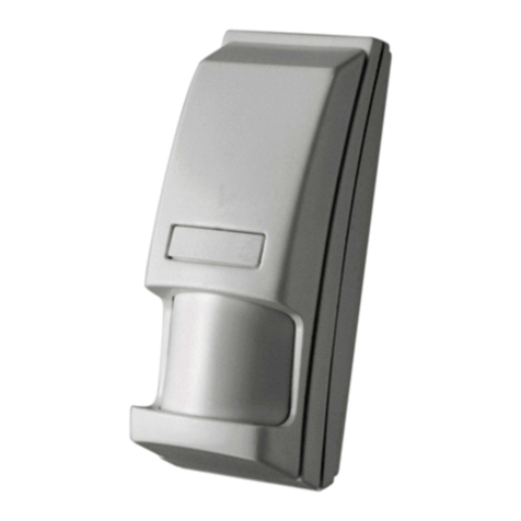
  9. Visonic MCPIR-2000 User manual

Visonic MCPIR-2000 User manual

DE3600 1









Fully Supervised PowerCode Wireless PIR Detector

Installation Instructions





The MCPIR-2000 is an advanced, fully supervised ultra low-current wireless
PIR that incorporates a PowerCode transmitter. Both transmitter and detector
circuits are powered by an on-board, long life 3.6 V Lithium battery.
Each MCPIR-2000 unit has a 24-bit ID code, randomly selected in the factory
from over 16 million possible combinations. This code is therefore unique and
virtually impossible to reproduce. Compatible PowerCode receivers are
designed to "learn" specific IDs and respond only to them.
Following detection, the MCPIR-2000 triggers the on-board transmitter which
transmits its specific PowerCode ID followed by an Alarm signal and status
designators for Tampering and Battery Condition. Alarm and other data are
thus forwarded to the alarm control panel or to a head-end computer,
depending on the type of system in which the detector is used.
Since messages transmitted by the MCPIR-2000 might collide with messages
transmitted by other PowerCode transmitters, a "smart" anti- collision
transmission sequence is used.
A periodic supervision message, distinguished by a specific marker, is
transmitted automatically once in 60 min. (USA) or 15 min. (Europe) or
according to local standards. The receiver is thus informed, that the particular
detector is taking an active part in the wireless network.
After triggering the transmitter, the MCPIR-2000 disarms itself to save battery
power. The detector rearms itself automatically (reverts to the ready state) 2
minutes after the last movement has been detected. A LED/ WALK-TEST
selector is used to override the 2-minute rearm timer during walk testing.
A programmable pulse counter is included in the unit for maximum immunity
against false alarms.
An entire library of interchangeable lenses, 25°vertical and 30°horizontal
adjustment, surface, corner or flush mounting installation from 0 to 17 feet
height, all these features enhance the detector's versatility of application and
make it a worthwhile unit to standardize on.
Figure 1. General View
Visonic Ltd.’s "SUPER-RED" lens library provides a
variety of 45 easy-to-change lens selection and
coverage patterns and includes:
•9 wide-angle lenses up to 140°
•3 long-range corridors up to 36 m (120 ft.)
•6 pet alleys
•3 finger curtains
•8 lenses for combined ceiling and room coverage
•10 lenses for 2-3 room and corridor coverage





OPTICAL
Standard Lens: No. 100 (see
Figure 2), 36 beams, 3 layers.
Upper Layer - 9 twin beams,
optically split to 18 beams.
Intermediate Layer - 5 twin
beams, 10°below upper layer.
Downward Layer - 4 twin beams,
angled 25°

below upper layer.
Field of View: 90°

wide angle.
Coverage range: Maximum 18 x
18 m (60 x 60 ft).
Interchangeable Lenses: See
SUPER-RED Lens Library.
Adjustment: Vertical +10°to -
15°, Horizontal up to 30°.
ELECTRICAL
Battery Type: 3.6 Volt lithium
thionyl chloride (LiSOCl
2
) battery,
size 1/2AA, Tadiran TL-5902.
Battery Capacity: 1.2 Ah nominal
Standby Current: 0.015 mA.
Transmit Current Drain: 9.5 mA
(including LED)
Battery Life Expectancy: 3 years (for typical use)
LED: Lights for 2 seconds upon transmission and upon motion
detection in the walk test mode.
Detector: Dual-element low-noise pyroelectric sensor.
Pulse Counter: Programmable to 1, 3 or 5 pulses.
Rearm Timer: 2 minutes after the last alarm; timer disabled in the
walk test mode.
WIRELESS
Frequency (MHz): 315, 433.92 or other frequencies according to
local requirements.
Transmission Sequence: 3 data bursts at variable intervals within
3 seconds.
Encoding: 24-bit factory selected ID code, over 16 million possible
combinations.
Message Length: 36 bits
Battery Supervision: Automatic reporting of battery status with
each alarm and with periodic autotest.
Tamper Alert: Reported at 3-minute intervals, until the tamper
switch is restored
ENVIRONMENTAL
Operating Temperature: -10°to 50°C (14°to 122°F).
Storage Temperature: -20°to 60°C (-4°F to 140°F).
RFI Protection: > 20 V/m up to 1000 MHz.
PHYSICAL
Weight: 105 g (3.7 oz).
Dimensions (H x W x D): 12 x 7 x 4.8 cm (4-3/4 x 2-3/4 x 1-7/8 in.)
Color: White.
Compliance with Standards: FCC Part 15, ETS300-220 and
MPT1349
OPTIONAL MOUNTING ACCESSORIES
SRF-201: Flush mounting adapter.
SRS-202: Mounting stand for portable applications.
BR-1: Swivel bracket for wall mounting.
BR-2: BR-1 + corner mounting adapter.
BR-3: BR-1 + ceiling mounting adapter.
Figure 2. Coverage Pattern -
Lens No. 100
2 DE3600





    !"
A. Insert a small screwdriver into the slot on top of the unit
(Figure 3). Press the blade in between the cover and the
base, then push downwards and lever backwards. The top
part of the cover (equipped with the lens) will snap free. You
may now hinge the top of the cover outward, separate the
bottom legs of the base from the slots in the cover and
remove the cover.
B. To remount the cover, insert the legs at the bottom of the
base into their respective slots in the bottom of the cover
and close by exerting slight upward pressure (Figure 4).
Figure 3. Removing the Cover
Figure 4. Remounting the cover
!#$$
To change or adjust a lens,
remove the front cover of the
detector (para. 3.1).
Release and remove the lens
retainers located on both sides
of the lens by pushing them out
from the inner side of the cover
(Fig. 5).
Insert a new lens with the smooth
surface facing out and the lens
number in the upper right corner
(when looked at from the inner
side of the cover).
Carefully center the lens by
sliding it right or left. Holding the
lens firmly in place, insert the
lens retainers from the front
(ridges pointed outward) and
push them into place until a
click is heard (see Fig. 6).
LENS
RETAINER
êê
LENS
Figure 5. Removing the Lens
Retainers
LENS
RETAINER
êê
Figure 6. Locking the Lens
$" !%# "&
Insert the battery as follows:
A. Remove the detector's front cover as in Para. 3.1 and push
the battery into the battery clip - observe polarity.
B. Press the tamper switch lever once and release it. This will
perform the reset necessary for smooth power up.
C. Put the cover on and watch the LED. It will flash once in 2
seconds for at least 15 seconds until the sensor stabilizes.
' $ "#  ( ! "#$  " 
 !#" )"*$ "&
Refer to the target receiver’s installation instructions and follow
the procedure given there for “teaching” transmitter IDs. It is
much easier to carry out this operation in close proximity to the
receiver, before actually mounting the detector in place.
+,)  ! )# 
The MCPIR-2000 can be mounted directly onto the wall (surface
mounted), or in a corner.
A. Select the mounting location so that an intruder's motion will
cross the beams of the selected pattern.
B. Determine the convenient mounting height.
NOTE: The vertical calibration scale on the detector's printed
circuit board is factory preset at -5
°
(see Table 1 for scale
application).
C. Where a single-layer pattern has been selected for pet
avoidance, install the detector as low as possible, usually 1.2 -
1.5 m (4 - 4.5 ft) while
still allowing the
beams to be directed
above the level of the pet’s activity.
D. To minimize false alarms, avoid aiming the detector at heaters,
sources of bright light, or windows subjected to direct sunlight.
E. Always mount the unit on a firm and stable surface.
-")  
Mount the base (equipped with the p.c. board) in the location and
height selected for optimum coverage.
For surface mounting use the two knockouts at the back of the
base; for corner mounting, use the knockouts on the angled sides
(see Figure 7).
Figure 7. Components Layout
./0$  !"#"#
Horizontal Adjustment
The coverage pattern can be adjusted horizontally ±15°by
shifting the lens to the left or right. To adjust the lens, remove the
lens retainers (see Para. 3.2), shift the lens carefully to the
desired position and re-insert the lens retainers into their places.
Vertical Adjusting Scale
The vertical scale adjustment (printed on the left side of the p.c.
board) and the plastic pointer on the base indicate (in degrees)
the vertical angle between the upper layer of the coverage
pattern and the horizontal line of the unit.
Table 1 gives the recommended scale adjustment of mounting
heights and coverage distances. The scale enables pattern
adjustment from +10°

to -15°, according to the installation height
and the required coverage range. Do not exceed the maximum
range of the selected lens, as indicated in the lens library catalog.
Table 1. Vertical Adjusting Scale
DE3600 3
To change the vertical-pattern adjustment, loosen the screw to slide
the PC board to the desired angle and then tighten the screw firmly.
Beam Masking Material
A special beam-masking material supplied with each detector can
be used to mask individual segments in the lens array which are
exposed to potential sources of false alarms (heaters, blowers,
pets, etc). The material is transparent to visible light but blocks
any infrared energy. To block individual beam(s), cut the masking
material to the exact dimensions of the segment(s) to be blocked,
remove the backing paper and apply the mask accurately to the
inside (smooth) surface of the lens on these segment(s).
In some cases, more than one layer may be required to
completely block the infrared energy.
1  !,$ "
MCPIR-2000 detectors are equipped with a programmable pulse
counter which can be set to count 1, 3 or 5 pulses, before
activating the wireless transmitter. To set the pulse counter, place
the jumper at the desired setting (1, 3 or 5 - see Fig. 8).
Figure 8. Setting the Pulse Counter
Note: Three pulses may be selected for all applications where
wide-angle, multi-beam lenses are used, such as illustrated in
Sections 1, 2, 3, 6 and 7 of the SUPER RED lens library.
Three pulses should never be used with lens No. 53 or with
long-range lenses from Sections 4 & 5 of the Lens Library.

23 #,4$ 
IMPORTANT! The range and the coverage area of the unit
should be checked at least once a year. To assure proper
continuous functioning, the end user should be instructed to
perform a walk test at the far end of the coverage pattern prior
to each time the alarm system is armed.
To save battery power in normal use, an automatic timer inhibits
the detector for approximately 2 minutes after transmitter
activation. The detector is automatically rearmed 2 minutes after
detection of the last motion.
For effective walk testing , it is necessary to override
the 2 minute timer by setting the LED/WALK-TEST
jumper to the TEST position as shown to the right.
Note: If the LED/walk-test jumper is forgotten in TST
position, the detector returns to ON position after
approximately 30 minutes, to save battery power.
IMPORTANT! Once the cover is replaced, the detector goes
through a stabilization period. The LED will flash once per 2
seconds until the detector has stabilized (stabilization time
is at least 15 seconds).
A. Walk-test the entire protected area by walking slowly across
the detector's field of view, observing the LED. Pause for 5
seconds after each test to allow the unit to complete its 3-
transmission sequence (see Para. A-2 in Appendix A). the
LED will light for 2 seconds.
B. Set the LED/WALK-TEST jumper to the ON position
as shown to the right. ⇐
Wait outside the coverage area. After five minutes,
re-enter the coverage area and verify that the LED
lights for 2 seconds upon detection.
C. If you continue moving, the unit will remain disabled due to the
2-minute battery saving timer. The unit will be rearmed
provided that no motion is detected for approximately 2
minutes, and will then be ready to detect and transmit.
D. When done, set the LED/WALK-TEST jumper to the
OFF position as shown to the right. ⇐
This setting is recommended to prevent unauthorized
people from tracing the detector’s coverage pattern.
5 #,))$$"$
A. Swivel Brackets
The BR-1 is a swivel, surface-mount bracket which provides
greater flexibility when setting the desired detection range. The
BR-1 is adjustable 30°downward and 45°left or right (Fig. 9).
The BR-2 is a similar swivel bracket kit for room corners.
The BR-3 is a similar swivel bracket kit for ceilings installations.
ATTENTION: With optional swivel brackets in use, the effective
detection range may differ from that indicated in Table 1.
Figure 9. Optional Swivel Brackets
B Flush Mount Bracket
(Fig. 10)
If necessary, the MCPIR-2000
may be flush mounted, using the
optional flush-mount bracket
SRF-201.
C. Mobile Stand (
Fig.
11)
A special stand, the SRS-202,
enables you to place the MCPIR-
2000 detector temporarily on
horizontal surfaces such as
shelves, tables, etc. This
accessory is especially suitable
for portable applications, where
the detector’s location should be
changed frequently.
Although designed mainly for
portable use, The SRS-202 can
be fixed permanently to a
horizontal surface, using the two
screw holes at its bottom. It can
also be fixed to a vertical
surface, provided that a very
strong adhesive is used.
Figure 10. SRF-201
Figure 11. SRS-202

DE3600
'3 6
'3 6'3 6
'3 6


'"/)  # $
Visonic Ltd. wireless systems are reliable and are tested to high
standards. However, due to the low transmitting power (required
by the FCC and other regulatory authorities), there are some
limitations to be considered:
A. A receiver may be blocked by radio signals sent on or near its
operating frequency, regardless of the digital code used.
B. A receiver responds to one transmitted signal at a time.
C. Wireless equipment should be tested regularly (at least once
a week) to discover sources of interference and to protect
against faults.
' 5,#)7 ! #/#"/$
WARNING! Changes or modifications to this unit not expressly
approved by the party responsible for compliance could void the
user's authority to operate the equipment.
This device complies with FCC Rules Part 15. Operation is
subject to two conditions: (1) This device may not cause harmful
interference, and (2) this device must accept any interference that
may be received or that may cause undesired operation.
This device complies with the European Council Directive EMC
89/336/EEC & 92/31/EEC and bears the CE mark and
certification.
89:3 ;
89:3 ;89:3 ;
89:3 ;



!7 "/$$#" # 


The PowerCode message transmitted by the MCPIR-2000
includes the detector's 24-bit ID and a status report (see Fig. A1).
Figure A1. Transmitted Data
A message includes the following data:
Detector's ID: Any message transmitted starts with the 24-
bit ID assigned to the particular detector unit.
Tamper / Restore: Upon removal of the unit's front cover, a
message will be transmitted with a "tamper marker" ON. If
the unit's cover is put back, a message will be transmitted
with the tamper marker OFF ("Tamper Restore").
Alarm: Once the detector is in alarm, a message will be
transmitted with an "Alarm marker" ON.
Low Battery: A special battery condition marker is used to
report the battery status in any message. The battery is
tested once an hour and if found low, the "low battery
marker" is set to ON in all following messages.

Supervision Message: A special "supervision message
marker", when set to ON, identifies the periodic supervision

messages transmitted automatically at 1 hour intervals. This
marker will be OFF in all other messages.
Transmitter Type: A special marker indicates the type of
the transmitter:
Supervised or non-supervised
Reports or does not report restorals after alarm
The MCPIR-2000 is supervised and does not report
restorals after alarms.
Checksum: Checksum bits at the end of the message allow
the receiver to determine whether an incoming message is
valid (error-free). This feature considerably upgrades the
reliability of the wireless communication link.
 ,,$
To overcome message collisions at the receiving end,
PowerCode transmitters transmit 3 data bursts at random
intervals, with 6 repetitions of the same message in each burst
(Fig. A2). This redundancy improves the probability of reception.
Note: Periodic supervision messages are an exception to this
rule - they consist of a single 6-message burst.
Figure A2. Anti-Collision Transmission Sequence


3 ;
3 ;3 ;
3 ;



Visonic Ltd. and/or its subsidiaries and its affiliates ("the Manufacturer") warrants its products hereinafter
referred to as "the Product" or "Products" to be in conformance with its own plans and specifications and to
be free of defects in materials and workmanship under normal use and service for a period of twelve months
from the date of shipment by the Manufacturer. The Manufacturer's obligations shall be limited within the
warranty period, at its option, to repair or replace the product or any part thereof. The Manufacturer shall not
be responsible for dismantling and/or reinstallation charges. To exercise the warranty the product must be
returned to the Manufacturer freight prepaid and insured.
This warranty does not apply in the following cases: improper installation, misuse, failure to follow
installation and operating instructions, alteration, abuse, accident or tampering, and repair by anyone other
than the Manufacturer.
This warranty is exclusive and expressly in lieu of all other warranties, obligations or liabilities, whether
written, oral, express or implied, including any warranty of merchantability or fitness for a particular purpose,
or otherwise. In no case shall the Manufacturer be liable to anyone for any consequential or incidental
damages for breach of this warranty or any other warranties whatsoever, as aforesaid.
This warranty shall not be modified, varied or extended, and the Manufacturer does not authorize any person
to act on its behalf in the modification, variation or extension of this warranty. This warranty shall apply to the
Product only. All products, accessories or attachments of others used in conjunction with the Product,
including batteries, shall be covered solely by their own warranty, if any. The Manufacturer shall not be liable
for any damage or loss whatsoever, whether directly, indirectly, incidentally, consequentially or otherwise,
caused by the malfunction of the Product due to products, accessories, or attachments of others, including
batteries, used in conjunction with the Products.
The Manufacturer does not represent that its Product may not be compromised and/or circumvented, or that
the Product will prevent any death, personal and/or bodily injury and/or damage to property resulting from
burglary, robbery, fire or otherwise, or that the Product will in all cases provide adequate warning or
protection. User understands that a properly installed and maintained alarm may only reduce the risk of
events such as burglary, robbery, and fire without warning, but it is not insurance or a guarantee that such
will not occur or that there will be no death, personal damage and/or damage to property as a result.
The Manufacturer shall have no liability for any death, personal and/or bodily injury and/or damage
to property or other loss whether direct, indirect, incidental, consequential or otherwise, based on a
claim that the Product failed to function. However, if the Manufacturer is held liable, whether directly or
indirectly, for any loss or damage arising under this limited warranty or otherwise, regardless of cause or
origin, the Manufacturer's maximum liability shall not in any case exceed the purchase price of the Product,
which shall be fixed as liquidated damages and not as a penalty, and shall be the complete and exclusive
remedy against the Manufacturer.
Warning: The user should follow the installation and operation instructions and among other things test the
Product and the whole system at least once a week. For various reasons, including, but not limited to,
changes in environmental conditions, electric or electronic disruptions and tampering, the Product may not
perform as expected. The user is advised to take all necessary precautions for his /her safety and the
protection of his/her property.
6/91
W.E.E.E. Product Recycling Declaration
For information regarding the recycling of this product you must contact the company from which you orignially purchased it. If you are discarding this product and not
returning it for repair then you must ensure that it is returned as identified by your supplier. This product is not to be thrown away with everyday waste.
Directive 2002/96/EC Waste Electrical and Electronic Equipment.
VISONIC LTD. (ISRAEL): P.O.B 22020 TEL-AVIV 61220 ISRAEL. PHONE: (972-3) 645-6789, FAX: (972-3) 645-6788
VISONIC INC. (U.S.A.):
65 WEST DUDLEY TOWN ROAD
, BLOOMFIELD CT. 06002-1911. PHONE: (860) 243-0833, (800) 223-0020 FAX: (860) 242-8094
VISONIC LTD. (UK): FRASER ROAD, PRIORY BUSINESS PARK, BEDFORD MK44 3WH. PHONE: (0870) 7300800 FAX: (0870) 7300801
INTERNET:
www.visonic.com
VISONIC LTD. 2002 MCPIR-2000 D-3600-0 NEW: DE3600- (REV. 2, 7/02)
P
Other Visonic Security Sensor manuals

Visonic Elpas User manual

Visonic

Visonic Elpas User manual

Visonic DISCOVERY K9-80 MCW - INSTALLER GUIDE User manual

Visonic

Visonic DISCOVERY K9-80 MCW - INSTALLER GUIDE User manual

Visonic MC-302V PG2 User manual

Visonic

Visonic MC-302V PG2 User manual

Visonic NEXT CAM PG2 User manual

Visonic

Visonic NEXT CAM PG2 User manual

Visonic MCW User manual

Visonic

Visonic MCW User manual

Visonic Vi-motion User manual

Visonic

Visonic Vi-motion User manual

Visonic DUET User manual

Visonic

Visonic DUET User manual

Visonic NEXT K9-85 MCW User manual

Visonic

Visonic NEXT K9-85 MCW User manual

Visonic CLIP-4N User manual

Visonic

Visonic CLIP-4N User manual

Visonic MR-4000 User manual

Visonic

Visonic MR-4000 User manual

Visonic SR-740 HEX PG2 User manual

Visonic

Visonic SR-740 HEX PG2 User manual

Visonic TOWER-20AM PG2 User manual

Visonic

Visonic TOWER-20AM PG2 User manual

Visonic DUO 240 - INSTALLER GUIDE User manual

Visonic

Visonic DUO 240 - INSTALLER GUIDE User manual

Visonic MCT-550 User manual

Visonic

Visonic MCT-550 User manual

Visonic NEXT K9-85 User manual

Visonic

Visonic NEXT K9-85 User manual

Visonic CLIP Series User manual

Visonic

Visonic CLIP Series User manual

Visonic DISCOVERY QUAD MCW User manual

Visonic

Visonic DISCOVERY QUAD MCW User manual

Visonic LEGACY User manual

Visonic

Visonic LEGACY User manual

Visonic SRN-2000W/PCN User manual

Visonic

Visonic SRN-2000W/PCN User manual

Visonic CLIP PG2 User manual

Visonic

Visonic CLIP PG2 User manual

Visonic CLIP MCW User manual

Visonic

Visonic CLIP MCW User manual

Visonic DISCOVERY PIR MCW User manual

Visonic

Visonic DISCOVERY PIR MCW User manual

Visonic DUET-AM C/O User manual

Visonic

Visonic DUET-AM C/O User manual

Visonic MP-802 K9-85 PG2 User manual

Visonic

Visonic MP-802 K9-85 PG2 User manual

Popular Security Sensor manuals by other brands

System Sensor B224BI-WH Installation and maintenance instructions

System Sensor

System Sensor B224BI-WH Installation and maintenance instructions

DeVilbiss MPV-623 Operation manual

DeVilbiss

DeVilbiss MPV-623 Operation manual

Firefly OMNIGUARD 540 Operating and service manual

Firefly

Firefly OMNIGUARD 540 Operating and service manual

Hytronik HIR22 Installation and instruction manual

Hytronik

Hytronik HIR22 Installation and instruction manual

Abexo P41 Assembly and use instructions

Abexo

Abexo P41 Assembly and use instructions

Powersolve RED00202A manual

Powersolve

Powersolve RED00202A manual

AJAX GlassProtect user manual

AJAX

AJAX GlassProtect user manual

Honeywell FIRE-LITE ALARMS H365 Installation and maintenance instructions

Honeywell

Honeywell FIRE-LITE ALARMS H365 Installation and maintenance instructions

Siemens FDOOTC241 Technical manual

Siemens

Siemens FDOOTC241 Technical manual

SkyLink PS-101 operating instructions

SkyLink

SkyLink PS-101 operating instructions

Mastitis 4x4 Q MAST manual

Mastitis

Mastitis 4x4 Q MAST manual

Plastrol CR-IR2/KP manual

Plastrol

Plastrol CR-IR2/KP manual

DÖRR HA-300 instruction manual

DÖRR

DÖRR HA-300 instruction manual

FORTEZA FM-60(24)-BT user manual

FORTEZA

FORTEZA FM-60(24)-BT user manual

LEGRAND Triscan 488TRI3W instruction manual

LEGRAND

LEGRAND Triscan 488TRI3W instruction manual

Covidien Nellcor PEDICAP Instructions for use

Covidien

Covidien Nellcor PEDICAP Instructions for use

AVE AF45362 manual

AVE

AVE AF45362 manual

Everflourish GAO instruction manual

Everflourish

Everflourish GAO instruction manual

manuals.online logo
manuals.online logoBrands
  • About & Mission
  • Contact us
  • Privacy Policy
  • Terms and Conditions

Copyright 2025 Manuals.Online. All Rights Reserved.