manuals.online logo
Brands
  1. Home
  2. •
  3. Brands
  4. •
  5. Visonic
  6. •
  7. Security Sensor
  8. •
  9. Visonic MP-841 User manual

Visonic MP-841 User manual

4 D-306173 MP-841 FLAT PIR
COMPLIANCE WITH STANDARDS
The MP-841 detector complies with the following standards:
Europe: EN 300328, EN 301489, EN 60950, EN 50130-4
This detector is compatible with the RED Directive 2014/53/EU of the European Parliament and of the Council of 16
April 2014
USA: FCC-CFR 47 Part 15
Canada: IC-RSS 247USA: UL-UL639Canada:ULC-S306
WARNING! Changes or modifications to this unit not expressly approved by the party responsible for compliance could void the user’s authority
to operate the equipment.
This device complies with Part 15 of the FCC Rules with Industry Canada license-exempt RSS standard(s). Operation is subject to the
following two conditions: (1) this device may not cause interference, and (2) this device must accept any interference, including
interference that may cause undesired operation of the device.
Le présent appareil est conforme aux CNR d'Industrie Canada applicables aux appareils radio exempts de licence. L'exploitation est
autorisée aux deux conditions suivantes : (1) l'appareil ne doit pas produire de brouillage, et (2) l'utilisateur de l'appareil doit accepter
tout brouillage radioélectrique subi, même si le brouillage est susceptible d'en compromettre le fonctionnement.
To comply with FCC Section 1.1310 for human exposure to radio frequency electromagnetic fields and IC requirements, implement the following
instruction: A distance of at least 20cm. between the equipment and all persons should be maintained during the operation of the equipment.
Le dispositif doit être placé à une distance d'au moins 20 cm à partir de toutes les personnes au cours de son fonctionnement normal. Les
antennes utilisées pour ce produit ne doivent pas être situés ou exploités conjointement avec une autre antenne ou transmett
NOTE: This equipment has been tested and found to comply with the limits for a Class B digital device, pursuant to part 15 of the FCC Rules.
These limits are designed to provide reasonable protection against harmful interference in a residential installation. This equipment generates,
uses and can radiate radio frequency energy and, if not installed and used in accordance with the instructions, may cause harmful interference to
radio communications. However, there is no guarantee that interference will not occur in a particular installation. If this equipment does cause
harmful interference to radio or television reception, which can be determined by turning the equipment off and on, the user is encouraged to try
to correct the interference by one or more of the following measures:
−Reorient or relocate the receiving antenna.
−Increase the separation between the equipment and receiver.
−Connect the equipment into an outlet on a circuit different from that to which the receiver is connected.
−Consult the dealer or an experienced radio/TV technician for help.
Cet équipement génère, utilize et peut émettre de l’énergie de fréquence radio et, s’il n’est pas installé et utilize conformément aux instructions du
fabricant, peut provoquer des interférences dangereuses pour les communications radio. Toutefois, rien ne garantit l’absence d’interférences
dans une installation particuliére. Si cet équipement provoque des interférences nuisibles au niveau de la réception radio ou television, ce qui
peut étre determine par la mise hors, puis sous tension de l’équipment, vous étes invite à essayer de corriger les interferences en pregnant les
mesures suivantes:
−Réorientez ou déplaces l’antenne réceptrice.
−Augmentez la distance qui sépare l’équipement et le récepteur.
−Branchez l’équipement à une prise d’un circuit different de celui auquel est branché le récepteur.
−Consultez le revendeur ou un technician radio/television expérimenté pour obtenir de l’aide.
SPECIAL COMMENTS
Even the most sophisticated detectors can sometimes be defeated or may fail to warn. Possible causes of failure are DC power failure or
improper connection, malicious masking of the lens, tampering with the optical system, decreased sensitivity in ambient temperatures close to
that of the human body and unexpected failure of a component part.
The above list includes the most common reasons for failure to detect intrusion, but is by no means comprehensive. It is therefore recommended
that the detector and the entire alarm system be checked weekly, to ensure proper performance.
An alarm system should not be regarded as a substitute for insurance. Home and property owners or renters should continue to insure their lives
and property, even though they are protected by an alarm system.
W.E.E.E. Product Recycling Declaration
For information regarding the recycling of this product you must contact the company from which you orignially purchased it. If you are discarding this product and not
returning it for repair then you must ensure that it is returned as identified by your supplier. This product is not to be thrown away with everyday waste.
Directive 2002/96/EC Waste Electrical and Electronic Equipment.
EMAIL: info@visonic.com
INTERNET: www.visonic.com
VISONIC LTD. 2017 MP-841 FLAT PIR D-306173 ( Rev. 4, 02/17)
D-306173 MP-841 FLAT PIR 1
MP-841
ZigBee Home Automation 1.2
Wireless Digital Pet Immune PIR Detector Installation Instructions
1. INTRODUCTION
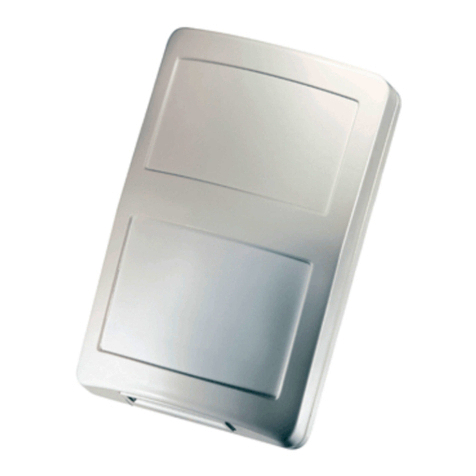
The MP-841 pet immune detector is a microprocessor-controlled wireless digital PIR detector supported by ZigBee Home Automation 1.2.
The detector has the following features:
•Detection distance up to 15 meters (49.2 ft.).
•Uniform Detection.
•White light immunity
•Enhanced Pet immunity up to 85Ibs (Target Specific Imaging™ (TSI) technology patented).
•Enhanced false alarm rejection (The advanced True Motion Recognition™ algorithm patented).
•No vertical adjustment is needed.
•In normal mode, after detection, the detector goes to sleep to save battery power. It wakes again and reverts to a ready state, if there is no
subsequent detection throughout the following 2-minute period.
•Temperature compensation.
•Front tamper protection.
•Black mirror technology provides excellent white light protection.
•Elegantly styled, sturdy case.
2 . SPECIFICATIONS
Detector Type
Dual element low-noise pyro electric sensor
Optical Data
27 “far” parabolic black mirrors (54 “beams”)
9 “near” cylinder black mirrors (18 "curtains”)
Pet immune protection is provided by a specific
optical attenuator on the mirror
Max. Coverage
15 x 15 m, (49.2 x 49.2 ft.) / 90°
Pet Immunity
Up to 38 kg (85 lb.) Pet immunity of 85 lb. is up
to 30 ft. (10 m) range.
ELECTRICAL
Internal Batteries
Two 3V Lithium batteries, type CR-123A. For
UL installations, use Panasonic and GP only
Nominal Battery
Capacity
1400 mAh
Battery Life
8 years of typical use.
Note: Inability to connect with wireless network,
or wireless link quality no higher than 20%
may significantly reduce the expected
battery life.
Battery Power
Test
Performed immediately upon battery insertion
and periodically every several hours.
FUNCTIONAL
Alarm Period
3 seconds
Visual Indications
Red LED lights for about 3 seconds during
transmission of alarm or tamper messages and
when motion is detected in walk test mode
only.
Red LED flashes during the power-up
stabilization period, or after restoring
(pressing) the tamper switch.
Red LED does not light during transmission of
supervision messages or alarm detection after
termination of walk test mode.
Rearm Timer
Rearms the detector 2 minutes after the last
alarm. Timer disabled in the walk test mode.
WIRELESS
Supported
Network
ZigBee H.A 1.2
Frequency
2.405 – 2.480 Ghz as per IEEE 802.15.4
Tamper Alert
Reported when a tamper event occurs and in
any subsequent message, until the tamper
switch is restored
MOUNTING
Height
1.8-2.4 m (6 - 8 ft.). For pet rejection, the
optimal height is 2.1 m (7 ft.)
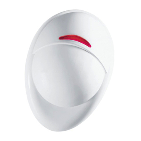
Installation
Options
Surface or corner
A. Red LED
B. Green LED
C. Tamper Switch
Figure 1 - MP-841
2 D-306173 MP-841 FLAT PIR
ENVIRONMENTAL
RFI Protection
>20 V/m up to 1000 MHz
Operating
Temperatures
-10°C to 50°C (14°F to 122°F)
Storage
Temperatures
-20°C to 60°C (-4°F to 140°F)
PHYSICAL
Size (H x W x D)
119 x 79 x 33.5 mm (4.68 x 3.11 x 1.31”)
Weight (with
batteries)
119 g (4.2 oz.)
Color
White
PATENTS
U.S. Patents 5,693,943 6,211,522
3. INSTALLATION
3.1 General Guidance
The following factors must be considered before selecting a location
for the detector:
1. Keep away from heat sources.
2. Do not expose to air drafts.
3. Do not install outdoors.
4. Avoid direct sunshine.
5. Do not install near high-voltage electrical lines.
6. Do not install behind partitions.
7. Always mount on a solid, stable surface.
Warning! Do not obscure partially or completely the detector’s field of
view.
Figure 2. General Guidelines
3.2 Installation Procedure
1. Press in this point; see Figure 3 Opening the unit for details.
2. Push in the direction of the arrow as shown in Figure 3 to
separate the detector from the bracket.
3. Mount the bracket on the wall.
4. Install new batteries.
-OR-
If batteries are already installed, pull the activation strip.
5. Mount the detector on the bracket by sliding it downward until a
click is heard.
6. Keep the protective film on the unit until after the unit is
mounted in its final location and ready for the walk test, then
remove it.
A. Use A1 or A2 for corner mounting, see Figure 4.
B. Use for surface mounting, see Figure 4.
C. Activation strip, see Figure 5.
Note: It is recommended to wait about 1 minute after battery removal, before inserting the new battery.
Caution! Risk of explosion if battery is replaced by an incorrect type. Dispose of used battery according to the manufacturer's instructions.
MP-841 shall be installed in accordance with the Standard for Installation and Classification of Burglar and Holdup Alarm Systems, UL 681.
Figure 3 – Opening the Unit
Figure 4 – Bracket Mounting
Figure 5 – Removing the Activation Strip
Figure 6 – Mounting Detector on Bracket
D-306173 MP-841 FLAT PIR 3
3.3 Replacing the Batteries
Figure 7 – Replacing Batteries
3.4 Activating and Pairing the Detector
To pair the detector to the Touchscreen control panel, you must set it to pairing mode.
1. First set the Touchscreen panel to pairing mode and then the detector.
2. To activate, pull the activation strip that protrudes from the back of the detector, see Figure 5.
3. The green LED (see Figure 1) blinks 3 times every 5 seconds (repeated up to 20 times) to indicate that the detector is searching for the
Touchscreen control panel.
Note: If detector pairing is not successful during the searching process – by tripping the motion detector or by pressing the tamper
switch – the searching process will restart.
4. Complete the pairing procedure on the Touchscreen control panel. For pairing instructions see the Touchscreen control panel’s
installation guide.
Note: Pairing should be performed before installation.
After the installation a good link to the panel is displayed when the Received Signal Strength Indicator (RSSI) indicated on the panel is higher
than -70dBm and the Link Quality Indicator (LQI) is stronger than 250. If the RSSI and LQI values are lower, you must change the location of the
detector.
3.5 Rebooting the Detector
To reboot the detector, complete the following steps:
1. Remove the battery cover.
2. Press and release the tamper switch for 1 to 2 seconds (see Figure 1).
3. Close the battery cover.
3.6 Returning the Detector to default mode
CAUTION! The default process removes the device from the network and enables re-pairing.
Prerequisite: Separate the detector from the bracket to remove both batteries. See Figure 7 for details.
1. Press and hold down the detectors tamper switch.
2. Insert one of the two batteries into the detector while observing battery polarity.
3. Release the tamper switch within 4 seconds (the LED blinks 3 times every 5 seconds).
4. To re-pair the detector, follow the instructions in section 3.4.
3.7 Walk Testing
Walk across the far end of coverage pattern in both directions. The LED should light for 2-3 seconds
each time your motion is detected.
Important! Instruct the user to perform a walk test at least once a week to verify the proper functioning
of the detector.
Note: After battery insertion or closing the cover (which results in closing the tamper switch) the LED
flashes for 2 minutes and the detector goes into walk-test mode for 15 minutes. In walk-test
mode the LED lights for every motion detected. After 15 minutes the detector automatically
enters normal mode in which the LED will not blink after detection.
TROUBLESHOOTING
If you encounter one of the following problems with the MP-841, perform the suggested remedy:
Problem
Remedy
Attempt to pair the sensor is unsuccessful.
Make sure that the sensor is reset to default mode and then set to
pairing mode, see section 3.4 for details.
The sensor and the Touchscreen panel do not communicate.
Perform the signal strength testing procedure described in the control
panel installation manual. Make sure that the signal is sufficient. If
necessary, replace the sensor’s battery.
The sensor sends a Low Battery indication.
To ensure continuous proper operation, replace both batteries within
two weeks of the first Low Battery indication.
Panel does not arm because of an unrecognized sensor malfunction. Consult with your installer or system provider before you disable
a zone.
Disable the sensor zone; see the control panel user manual for details.
Note that disabling a sensor zone lowers the overall security level of
the system.
1. Press upward to separate the detector
from the bracket.
2. Replace the batteries.
3. Put back the detector on the bracket.
Figure 8 – Coverage Pattern Walk Test
4 D-306173 MP-841 FLAT PIR
COMPLIANCE WITH STANDARDS
The MP-841 detector complies with the following standards:
Europe: EN 300328, EN 301489, EN 60950, EN 50130-4
This detector is compatible with the RED Directive 2014/53/EU of the European Parliament and of the Council of 16
April 2014
USA: FCC-CFR 47 Part 15
Canada: IC-RSS 247USA: UL-UL639Canada:ULC-S306
WARNING! Changes or modifications to this unit not expressly approved by the party responsible for compliance could void the user’s authority
to operate the equipment.
This device complies with Part 15 of the FCC Rules with Industry Canada license-exempt RSS standard(s). Operation is subject to the
following two conditions: (1) this device may not cause interference, and (2) this device must accept any interference, including
interference that may cause undesired operation of the device.
Le présent appareil est conforme aux CNR d'Industrie Canada applicables aux appareils radio exempts de licence. L'exploitation est
autorisée aux deux conditions suivantes : (1) l'appareil ne doit pas produire de brouillage, et (2) l'utilisateur de l'appareil doit accepter
tout brouillage radioélectrique subi, même si le brouillage est susceptible d'en compromettre le fonctionnement.
To comply with FCC Section 1.1310 for human exposure to radio frequency electromagnetic fields and IC requirements, implement the following
instruction: A distance of at least 20cm. between the equipment and all persons should be maintained during the operation of the equipment.
Le dispositif doit être placé à une distance d'au moins 20 cm à partir de toutes les personnes au cours de son fonctionnement normal. Les
antennes utilisées pour ce produit ne doivent pas être situés ou exploités conjointement avec une autre antenne ou transmett
NOTE: This equipment has been tested and found to comply with the limits for a Class B digital device, pursuant to part 15 of the FCC Rules.
These limits are designed to provide reasonable protection against harmful interference in a residential installation. This equipment generates,
uses and can radiate radio frequency energy and, if not installed and used in accordance with the instructions, may cause harmful interference to
radio communications. However, there is no guarantee that interference will not occur in a particular installation. If this equipment does cause
harmful interference to radio or television reception, which can be determined by turning the equipment off and on, the user is encouraged to try
to correct the interference by one or more of the following measures:
−Reorient or relocate the receiving antenna.
−Increase the separation between the equipment and receiver.
−Connect the equipment into an outlet on a circuit different from that to which the receiver is connected.
−Consult the dealer or an experienced radio/TV technician for help.
Cet équipement génère, utilize et peut émettre de l’énergie de fréquence radio et, s’il n’est pas installé et utilize conformément aux instructions du
fabricant, peut provoquer des interférences dangereuses pour les communications radio. Toutefois, rien ne garantit l’absence d’interférences
dans une installation particuliére. Si cet équipement provoque des interférences nuisibles au niveau de la réception radio ou television, ce qui
peut étre determine par la mise hors, puis sous tension de l’équipment, vous étes invite à essayer de corriger les interferences en pregnant les
mesures suivantes:
−Réorientez ou déplaces l’antenne réceptrice.
−Augmentez la distance qui sépare l’équipement et le récepteur.
−Branchez l’équipement à une prise d’un circuit different de celui auquel est branché le récepteur.
−Consultez le revendeur ou un technician radio/television expérimenté pour obtenir de l’aide.
SPECIAL COMMENTS
Even the most sophisticated detectors can sometimes be defeated or may fail to warn. Possible causes of failure are DC power failure or
improper connection, malicious masking of the lens, tampering with the optical system, decreased sensitivity in ambient temperatures close to
that of the human body and unexpected failure of a component part.
The above list includes the most common reasons for failure to detect intrusion, but is by no means comprehensive. It is therefore recommended
that the detector and the entire alarm system be checked weekly, to ensure proper performance.
An alarm system should not be regarded as a substitute for insurance. Home and property owners or renters should continue to insure their lives
and property, even though they are protected by an alarm system.
W.E.E.E. Product Recycling Declaration
For information regarding the recycling of this product you must contact the company from which you orignially purchased it. If you are discarding this product and not
returning it for repair then you must ensure that it is returned as identified by your supplier. This product is not to be thrown away with everyday waste.
Directive 2002/96/EC Waste Electrical and Electronic Equipment.
EMAIL: [email protected]
INTERNET: www.visonic.com
VISONIC LTD. 2017 MP-841 FLAT PIR D-306173 ( Rev. 4, 02/17)
D-306173 MP-841 FLAT PIR 1
MP-841
ZigBee Home Automation 1.2
Wireless Digital Pet Immune PIR Detector Installation Instructions
1. INTRODUCTION
The MP-841 pet immune detector is a microprocessor-controlled wireless digital PIR detector supported by ZigBee Home Automation 1.2.
The detector has the following features:
•Detection distance up to 15 meters (49.2 ft.).
•Uniform Detection.
•White light immunity
•Enhanced Pet immunity up to 85Ibs (Target Specific Imaging™ (TSI) technology patented).
•Enhanced false alarm rejection (The advanced True Motion Recognition™ algorithm patented).
•No vertical adjustment is needed.
•In normal mode, after detection, the detector goes to sleep to save battery power. It wakes again and reverts to a ready state, if there is no
subsequent detection throughout the following 2-minute period.
•Temperature compensation.
•Front tamper protection.
•Black mirror technology provides excellent white light protection.
•Elegantly styled, sturdy case.
2 . SPECIFICATIONS
Detector Type
Dual element low-noise pyro electric sensor
Optical Data
27 “far” parabolic black mirrors (54 “beams”)
9 “near” cylinder black mirrors (18 "curtains”)
Pet immune protection is provided by a specific
optical attenuator on the mirror
Max. Coverage
15 x 15 m, (49.2 x 49.2 ft.) / 90°
Pet Immunity
Up to 38 kg (85 lb.) Pet immunity of 85 lb. is up
to 30 ft. (10 m) range.
ELECTRICAL
Internal Batteries
Two 3V Lithium batteries, type CR-123A. For
UL installations, use Panasonic and GP only
Nominal Battery
Capacity
1400 mAh
Battery Life
8 years of typical use.
Note: Inability to connect with wireless network,
or wireless link quality no higher than 20%
may significantly reduce the expected
battery life.
Battery Power
Test
Performed immediately upon battery insertion
and periodically every several hours.
FUNCTIONAL
Alarm Period
3 seconds
Visual Indications
Red LED lights for about 3 seconds during
transmission of alarm or tamper messages and
when motion is detected in walk test mode
only.
Red LED flashes during the power-up
stabilization period, or after restoring
(pressing) the tamper switch.
Red LED does not light during transmission of
supervision messages or alarm detection after
termination of walk test mode.
Rearm Timer
Rearms the detector 2 minutes after the last
alarm. Timer disabled in the walk test mode.
WIRELESS
Supported
Network
ZigBee H.A 1.2
Frequency
2.405 – 2.480 Ghz as per IEEE 802.15.4
Tamper Alert
Reported when a tamper event occurs and in
any subsequent message, until the tamper
switch is restored
MOUNTING
Height
1.8-2.4 m (6 - 8 ft.). For pet rejection, the
optimal height is 2.1 m (7 ft.)
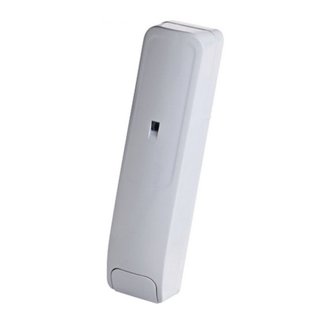
Installation
Options
Surface or corner
A. Red LED
B. Green LED
C. Tamper Switch
Figure 1 - MP-841

Other Visonic Security Sensor manuals

Visonic CLIP SMA User manual

Visonic

Visonic CLIP SMA User manual

Visonic SRN-2000W/PCN User manual

Visonic

Visonic SRN-2000W/PCN User manual

Visonic DE1260 DISCOVERY QUAD User manual

Visonic

Visonic DE1260 DISCOVERY QUAD User manual

Visonic NEXT PLUS PIR / K9-85 User manual

Visonic

Visonic NEXT PLUS PIR / K9-85 User manual

Visonic Elpas User manual

Visonic

Visonic Elpas User manual

Visonic MP-802 K9-85 PG2 User manual

Visonic

Visonic MP-802 K9-85 PG2 User manual

Visonic K-980D User manual

Visonic

Visonic K-980D User manual

Visonic NEXT PIR MCW User manual

Visonic

Visonic NEXT PIR MCW User manual

Visonic V-MOTION MCW User manual

Visonic

Visonic V-MOTION MCW User manual

Visonic NEXT K9-85 User manual

Visonic

Visonic NEXT K9-85 User manual

Visonic TOWER-20AM PG2 User manual

Visonic

Visonic TOWER-20AM PG2 User manual

Visonic MP-840 K9-85 User manual

Visonic

Visonic MP-840 K9-85 User manual

Visonic Logica User manual

Visonic

Visonic Logica User manual

Visonic DUO 240 - INSTALLER GUIDE User manual

Visonic

Visonic DUO 240 - INSTALLER GUIDE User manual

Visonic MCPIR-2000 User manual

Visonic

Visonic MCPIR-2000 User manual

Visonic DISC MCW User manual

Visonic

Visonic DISC MCW User manual

Visonic MCT-560 User manual

Visonic

Visonic MCT-560 User manual

Visonic MCT-302 User manual

Visonic

Visonic MCT-302 User manual

Visonic DUET User manual

Visonic

Visonic DUET User manual

Visonic DUET-AM C/O Assembly instructions

Visonic

Visonic DUET-AM C/O Assembly instructions

Visonic Quatro+ User manual

Visonic

Visonic Quatro+ User manual

Visonic TOWER 40 User manual

Visonic

Visonic TOWER 40 User manual

Visonic NEXT PG2 - User manual

Visonic

Visonic NEXT PG2 - User manual

Visonic DISCOVERY K9-80 User manual

Visonic

Visonic DISCOVERY K9-80 User manual

Popular Security Sensor manuals by other brands

Bosch Anatel Professional Series installation instructions

Bosch

Bosch Anatel Professional Series installation instructions

Siemens AS Series manual

Siemens

Siemens AS Series manual

Di-soric LAT52-80IU-RB5 quick start guide

Di-soric

Di-soric LAT52-80IU-RB5 quick start guide

DANLERS SILVAIR MESH-HBWD DALI quick start guide

DANLERS

DANLERS SILVAIR MESH-HBWD DALI quick start guide

OPTEX FA V Series instruction manual

OPTEX FA

OPTEX FA V Series instruction manual

GD Import 046555 manual

GD Import

GD Import 046555 manual

Stahl FX15 Series operating instructions

Stahl

Stahl FX15 Series operating instructions

Dectris PILATUS3 R Technical Specifications and Operating Procedure

Dectris

Dectris PILATUS3 R Technical Specifications and Operating Procedure

PCB Piezotronics 117B221 Installation and operating manual

PCB Piezotronics

PCB Piezotronics 117B221 Installation and operating manual

Buckingham Buck LeverJust 9M8 Series instructions

Buckingham

Buckingham Buck LeverJust 9M8 Series instructions

B.E.G. LUXOMAT PD4-M-1C-GH-AP quick start guide

B.E.G. LUXOMAT

B.E.G. LUXOMAT PD4-M-1C-GH-AP quick start guide

Bosch ISW-EN1262 installation guide

Bosch

Bosch ISW-EN1262 installation guide

Apogee Instruments SQ-100X Series owner's manual

Apogee Instruments

Apogee Instruments SQ-100X Series owner's manual

Rielta FOTON-SH2 installation guide

Rielta

Rielta FOTON-SH2 installation guide

Inficon TEK-Mate operating manual

Inficon

Inficon TEK-Mate operating manual

CENS MINO user guide

CENS

CENS MINO user guide

Glasdon Rebound Signmaster installation instructions

Glasdon

Glasdon Rebound Signmaster installation instructions

urmet domus 1033/127 quick start guide

urmet domus

urmet domus 1033/127 quick start guide

manuals.online logo
manuals.online logoBrands
  • About & Mission
  • Contact us
  • Privacy Policy
  • Terms and Conditions

Copyright 2025 Manuals.Online. All Rights Reserved.