manuals.online logo
Brands
  1. Home
  2. •
  3. Brands
  4. •
  5. Visonic
  6. •
  7. Security Sensor
  8. •
  9. Visonic DA-5 User manual

Visonic DA-5 User manual

DE1704 1
DA
DADA
DA-5
-5-5
-5
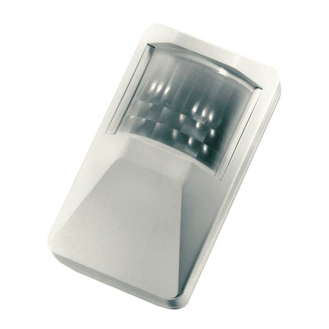
PIR Detector for Automatic Door Control Installation Instructions
1
11
1. INTRODUCTION
. INTRODUCTION. INTRODUCTION
. INTRODUCTION
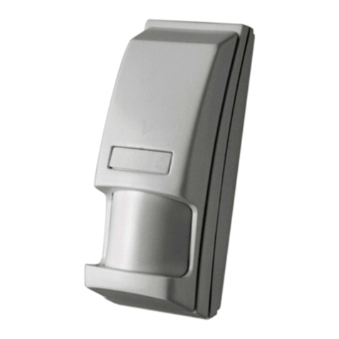
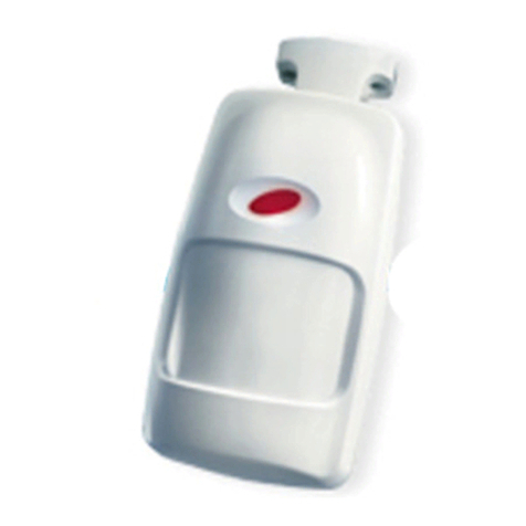
The DA-5 is a PIR motion detector designed for use with access
control and automatic door opening systems. It can be installed at
various heights on the wall above the door (Figure 1) or on the
ceiling (Figure 2), with its detection pattern directed at the floor in
front of the door. Upon detection of motion, the on-board
changeover relay energizes for a predetermined period. The relay
pull-in time is adjustable between 1 and 60 seconds with an
on-board timer control.
Operating power for the DA-5 may be supplied from a 12 or 24V
AC or DC source. A jumper is provided on the printed circuit
board for selecting the input voltage. Figure 1. Wall Mount
Configuration
Figure 2. Ceiling Mount
Configuration
2
22
2. SPECIFICATIONS
. SPECIFICATIONS. SPECIFICATIONS
. SPECIFICATIONS
OPTICAL
Detection Lens: Lens No. 74.
Detection Zones: 3 zones (A, B and C). 7 beams per zone.
ELECTRICAL
Input Voltage: 12/24VAC/DC (protected against reverse polarity)
Current Drain: 7 mA standby, 50 mA max @ 12 VDC; 14 mA
standby, 65 mA max @ 12 VAC
7 mA standby, 50 mA max. @ 24 VDC; 15 mA standby, 80 mA
max. @ 24 VAC
Output Relay Pull-in Period: 3 to 60 seconds, adjustable.
Relay Switching Capability: 2 A max. at 28 V AC or DC.
Detector Type: Dual-element pyroelectric sensor.
MOUNTING
Alternatives: Wall or ceiling mounting above the door. Surface
mountable on top of a standard single-gang electrical switchbox.
Height: 2.15 - 3 m (7 - 10 ft)
ENVIRONMENTAL
Operating Temperature: -10°C to 50°C (14°F to 122°F)
Storage Temperature: -20°C to 60°C (-4°F to 140°F)
Intended Use: Indoors or in water/rain-protected outdoor areas.
PHYSICAL
Size: 105 x 65 x 53 mm (4-1/10 x 2-1/2 x 2-1/10 in.).
Weight: 95 g (3.3 oz).
Color: White.
3
33
3. INSTALLATION
. INSTALLATION. INSTALLATION
. INSTALLATION
3.1 Construction Details
A. General Data
The unit consists of a plastic
base to which the electronic
module is fastened, and a
cover assembly with a curved
surface to which the milky
white lens is attached. The
cover must be removed for:
- Installation and wiring
- Adjusting the timer
- Selecting the input voltage
- Inverting the lens for ceiling
installation.
B. Lens Description
The DA-5 uses lens No. 74
that has 3 arrays of lens seg-
ments (Fig 3). Each array
provides a detection zone,
and all 3 zones combine to
form the entire detection
pattern (see Figures 5 thru 8).
Figure 3. Lens Division into
Detection Zones
Figure 4. Removing the Cover
Any detection zone or lens segment may be masked (para. 3.8).
The lens is factory set as required for wall mounting, but may be
easily inverted for ceiling mounting (para. 3.3).
C. Cover Removal
To separate the cover from the base, insert a screwdriver blade
into the slot provided between the cover and the base. Twist the
screwdriver slightly or move the handle down. The cover will
swing outward, ready for removal by hand.
3.2 Detection Patterns
A. Over-the-Door Wall Mounting
The DA-5 may be wall-mounted at various heights above the
door, centered with respect to the doorframe. Increasing the
mounting height will cause the coverage pattern to expand, as
demonstrated in figures 5 - 8. Note that detection zones B and C
partially overlap.
B. Ceiling Mounting
If the DA-5 is mounted on the ceiling, the detection patterns will
resemble those obtained with the unit mounted at the corres-
ponding height on the wall.
3.3 Ceiling Installation
Ceiling mounting requires the lens be inverted in its window.
The lens is held in place by a flexible plastic retainer. The lens
number (74) is engraved on the inner grooved surface of the lens
near the top rim (see Figure 9).
To invert the lens, proceed as follows:
A. Hold the cover assembly in the palm of your hand.
B. Seize the flat extractor tab (part of the lens retainer) between
two fingers of your other hand.
C. Press the extractor tab slightly down and pull it toward the
opposite side of the cover. This will dislodge the lens retainer,
which can then be removed.
D. Push the lens carefully out. Invert it (180° rotation) and place it
again in the lens window. The lens number should now be
near the 4 small plastic stoppers. Verify that the lens is snug
against the lens window frame.
E. Insert the straight, smooth edge of the lens retainer into the
deep end of the lens window. Then press the extractor tab
down until the near edge of the lens retainer snaps into place.
2DE1704
Figure 5. Mounting Height
2.15 m (7 ft)
Figure 6. Mounting Height
2.45 m (8 ft)
Figure 7. Mounting Height
2.78 m (9 ft)
Figure 8. Mounting Height
3.05 m (10 ft)
Figure 9. DA-5 Exploded View
3.4 Installation
The DA-5 is suitable for indoor or water/rain protected outdoor
installations. The minimum height for wall installation is 2.15 m
(7 ft) slightly above the door frame’s center. Remove the DA-5
cover (para. 3.1C). Two elongated holes are available in the base
for wall mounting (Fig. 10).
Note: The spacing between the mounting holes permits
installation of the DA-5 on a standard single-gang electrical
switchbox.
Figure 10. Components Layout
3.5 Wiring
The wiring configuration depends on the door control circuit in
use. The output relay contacts of the DA-5 can switch currents up
to 2A at 28 VAC or DC. Refer to Fig. 11 and connect as follows:
A. Wire the output relay's C and N.O. (or C and N.C.) contacts to
switch the door control device on and off, as required for the
door control circuit in use.
Warning! Verify that the input voltage jumper is positioned
correctly. For 12V operation, install it across the two pins. If
the power source is 24 V, remove the jumper and install it on
a single pin to prevent it from getting lost.
B. Connect the power supply
leads to the 12/24 V (+) and
(–) terminals. The unit
accepts both AC and DC
inputs. When using an AC
supply, disregard the (+)
and (–) markings. Figure 11.Terminal Block.
C. Seal all wire entry holes with RTV (clear silicone sealant) to
prevent insects and air currents from entering the unit.
3.6 Timer Adjustment
The relay timer is adjustable from 3 seconds to 1 minute, as
required for triggering the door control mechanism. Rotate the
knob towards MIN to decrease the relay pull-in time, and towards
MAX to increase the relay pull in time. The results of your
adjustment can be verified by watching the on-board LED, which
will be lit as long as the output relay is energized.
Note: For an accurate timer adjustment test, the cover must be
installed.
3.7 Testing
A. Mount the cover by pushing it onto the base until it snaps into
place with a click.
B. Apply power to the DA-5 and wait 5 minutes for the unit to
warm up and stabilize before testing.
C. Test the DA-5 by walking towards the door through the
detector’s field of view. Verify that the LED lights and the relay
pulls in each time the detection pattern is crossed. If operation
is erratic, readjust the timer control of the DA-5.
D. If the coverage pattern is too far from the door, you can mask
the farthest beam array (para. 3.8).
3.8 Beam Masking
Ordinary opaque masking tape can be used to mask individual
lens segments of any one of the three detection zones, or an
entire zone (Fig. 3). The masking tape will prevent the infrared
energy from reaching the sensor through the blocked segment.
Cut a masking tape patch that fits the dimensions of the lens area
you wish to block. Apply it accurately to the inner (grooved)
surface of the appropriate segment(s). In some cases, more than
one layer of the masking tape may be required to completely
block the infrared energy.
DE1704 3
WARRANTY
WARRANTYWARRANTY
WARRANTY
Visonic Ltd. and/or its subsidiaries and its affiliates ("the Manufacturer") warrants its
products hereinafter referred to as "the Product" or "Products" to be in conformance with
its own plans and specifications and to be free of defects in materials and workmanship
under normal use and service for a period of twelve months from the date of shipment by
the Manufacturer. The Manufacturer's obligations shall be limited within the warranty
period, at its option, to repair or replace the product or any part thereof. The Manufacturer
shall not be responsible for dismantling and/or reinstallation charges. To exercise the
warranty the product must be returned to the Manufacturer freight prepaid and insured.
This warranty does not apply in the following cases: improper installation, misuse,
failure to follow installation and operating instructions, alteration, abuse, accident or
tampering, and repair by anyone other than the Manufacturer.
This warranty is exclusive and expressly in lieu of all other warranties, obligations or
liabilities, whether written, oral, express or implied, including any warranty of
merchantability or fitness for a particular purpose, or otherwise. In no case shall the
Manufacturer be liable to anyone for any consequential or incidental damages for breach
of this warranty or any other warranties whatsoever, as aforesaid.
This warranty shall not be modified, varied or extended, and the Manufacturer does not
authorize any person to act on its behalf in the modification, variation or extension of this
warranty. This warranty shall apply to the Product only. All products, accessories or
attachments of others used in conjunction with the Product, including batteries, shall be
covered solely by their own warranty, if any. The Manufacturer shall not be liable for any
damage or loss whatsoever, whether directly, indirectly, incidentally, consequentially or
otherwise, caused by the malfunction of the Product due to products, accessories, or
attachments of others, including batteries, used in conjunction with the Products.
The Manufacturer does not represent that its Product may not be compromised and/or
circumvented, or that the Product will prevent any death, personal and/or bodily injury
and/or damage to property resulting from burglary, robbery, fire or otherwise, or that the
Product will in all cases provide adequate warning or protection. User understands that a
properly installed and maintained alarm may only reduce the risk of events such as
burglary, robbery, and fire without warning, but it is not insurance or a guarantee that such
will not occur or that there will be no death, personal damage and/or damage to property
as a result.
The Manufacturer shall have no liability for any death, personal and/or bodily injury
and/or damage to property or other loss whether direct, indirect, incidental,
consequential or otherwise, based on a claim that the Product failed to function.
However, if the Manufacturer is held liable, whether directly or indirectly, for any loss or
damage arising under this limited warranty or otherwise, regardless of cause or origin, the
Manufacturer's maximum liability shall not in any case exceed the purchase price of the
Product, which shall be fixed as liquidated damages and not as a penalty, and shall be the
complete and exclusive remedy against the Manufacturer.
Warning: The user should follow the installation and operation instructions and among
other things test the Product and the whole system at least once a week. For various
reasons, including, but not limited to, changes in environmental conditions, electric or
electronic disruptions and tampering, the Product may not perform as expected. The user
is advised to take all necessary precautions for his /her safety and the protection of
his/her property.
6/91
VISONIC LTD. (ISRAEL): P.O.B 22020 TEL-AVIV 61220 ISRAEL. PHONE: (972-3) 645-6789, FAX: (972-3) 645-6788
VISONIC INC. (U.S.A.): 10 NORTHWOOD DRIVE, BLOOMFIELD CT. 06002-1911. PHONE: (860) 243-0833, (800) 223-0020 FAX: (860) 242-8094
VISONIC LTD. (UK): FRASER ROAD, PRIORY BUSINESS PARK, BEDFORD MK44 3WH. PHONE: (0870) 7300800 FAX: (0870) 7300801
INTERNET: www.visonic.com
VISONIC LTD. 1998 DA-5 D-1704-0 NEW : DE1704- (REV. 2 , 4/98)

Other Visonic Security Sensor manuals

Visonic DUO 220 User manual

Visonic

Visonic DUO 220 User manual

Visonic CLIP-4N User manual

Visonic

Visonic CLIP-4N User manual

Visonic DUO 240 User manual

Visonic

Visonic DUO 240 User manual

Visonic DISCOVERY K9-80 MCW - INSTALLER GUIDE User manual

Visonic

Visonic DISCOVERY K9-80 MCW - INSTALLER GUIDE User manual

Visonic DISC MCW User manual

Visonic

Visonic DISC MCW User manual

Visonic SPD-1000 User manual

Visonic

Visonic SPD-1000 User manual

Visonic K-980W User manual

Visonic

Visonic K-980W User manual

Visonic CLIP Series User manual

Visonic

Visonic CLIP Series User manual

Visonic DUO 240 - INSTALLER GUIDE User manual

Visonic

Visonic DUO 240 - INSTALLER GUIDE User manual

Visonic Elpas User manual

Visonic

Visonic Elpas User manual

Visonic MCT-560 User manual

Visonic

Visonic MCT-560 User manual

Visonic MC-302V PG2 User manual

Visonic

Visonic MC-302V PG2 User manual

Visonic NEXT PG2 - User manual

Visonic

Visonic NEXT PG2 - User manual

Visonic NEXT PLUS PIR / K9-85 User manual

Visonic

Visonic NEXT PLUS PIR / K9-85 User manual

Visonic MCT-425 User manual

Visonic

Visonic MCT-425 User manual

Visonic XHS1-TY User manual

Visonic

Visonic XHS1-TY User manual

Visonic POWERMAX - User manual

Visonic

Visonic POWERMAX - User manual

Visonic MP-802 K9-85 PG2 User manual

Visonic

Visonic MP-802 K9-85 PG2 User manual

Visonic TOWER 20 AM MCW User manual

Visonic

Visonic TOWER 20 AM MCW User manual

Visonic NEXT CAM PG2 User manual

Visonic

Visonic NEXT CAM PG2 User manual

Visonic CLIP MCW User manual

Visonic

Visonic CLIP MCW User manual

Visonic MCT-442 User manual

Visonic

Visonic MCT-442 User manual

Visonic TOWER-20AM PG2 User manual

Visonic

Visonic TOWER-20AM PG2 User manual

Visonic MCT-302 User manual

Visonic

Visonic MCT-302 User manual

Popular Security Sensor manuals by other brands

Nidec WL10 Series instruction manual

Nidec

Nidec WL10 Series instruction manual

Treasure Cove Vibra-Phone 280 quick start guide

Treasure Cove

Treasure Cove Vibra-Phone 280 quick start guide

Optex BX SHIELD quick start guide

Optex

Optex BX SHIELD quick start guide

InnoSenT SMR-313 user manual

InnoSenT

InnoSenT SMR-313 user manual

SEBSON GS412 operating instructions

SEBSON

SEBSON GS412 operating instructions

FAG Detector III user manual

FAG

FAG Detector III user manual

Vivax Metrotech VM-550 user guide

Vivax Metrotech

Vivax Metrotech VM-550 user guide

Atom AT4101/PIR/WHT instruction manual

Atom

Atom AT4101/PIR/WHT instruction manual

IP44.de custo control Instructions for use

IP44.de

IP44.de custo control Instructions for use

BEMKO SES08WH Instruction

BEMKO

BEMKO SES08WH Instruction

Datalogic SG4-Extended Series quick guide

Datalogic

Datalogic SG4-Extended Series quick guide

Orbis CIRCUMAT PRO CR quick guide

Orbis

Orbis CIRCUMAT PRO CR quick guide

Takex SSP-S200 Series manual

Takex

Takex SSP-S200 Series manual

Interlogix DC418 Operation and installation manual

Interlogix

Interlogix DC418 Operation and installation manual

Dräger Flame 3000 Instructions for use

Dräger

Dräger Flame 3000 Instructions for use

NK TECHNOLOGIES AG3 Series instructions

NK TECHNOLOGIES

NK TECHNOLOGIES AG3 Series instructions

Honeywell Friedland FGGA08 Series Quick installation guide

Honeywell

Honeywell Friedland FGGA08 Series Quick installation guide

Tempo Fitness 88 instruction manual

Tempo Fitness

Tempo Fitness 88 instruction manual

manuals.online logo
manuals.online logoBrands
  • About & Mission
  • Contact us
  • Privacy Policy
  • Terms and Conditions

Copyright 2025 Manuals.Online. All Rights Reserved.