Vitrum On-Off Wireless Owner's manual

HOME CONTROL
THINK SIMPLE
EN
INSTALLATION AND OPERATION
Vitrum On-Off Wireless

INDEX
0. Before starting ................ 3
1. Electrical connections ........... 4
2. Positioning the glass decor panel... 8
3. Vitrum is intelligent ............ 9
4.
Configuration of the type of switch
12
5. Advanced functions ........... 15
6. Factory reset................. 19
7. Supervision.................. 21
8. Compatibility ................ 22
9. Compliance with ec directives ... 22
MAIN TECHNICAL SPECIFICATIONS
. . 23

3
0. BEFORE STARTING
The Vitrum system that you have purchased is designed for connection to your
existing 230V power supply circuit. Before commencing installation, ensure that the
mains power supply had been disconnected by setting the main switch on your
electricity meter to
OFF
.
Do not re-connect the power supply and start using Vitrum
until all connections have been correctly completed and the Vitrum unit has been
inserted into the wall-mounting box.
Vitrum must be installed by a professional electrician who is
qualified to operate on electrical power circuits in full compliance
with all current safety legislation.
For each device, connect the power supply and the return wire from the actuators
as shown in the circuit diagrams printed on the rear of the boxes in the vicinity of
the terminal block. Refer exclusively to the circuit diagrams contained in this manual,
especially if connecting the system without an earth wire.
Carefully check that the wires and connectors are securely fastened. After
securing the unit to the wall-mounting box, temporarily use the plastic cover
for protection until the glass décor plate is fitted.
Do not install Vitrum in the vicinity of sources of heat or in conditions of high humidity.
IMPORTANT: Fit a rapid-acting fuse with a high switching capacity that is
suitable for the load applied to the device.

4
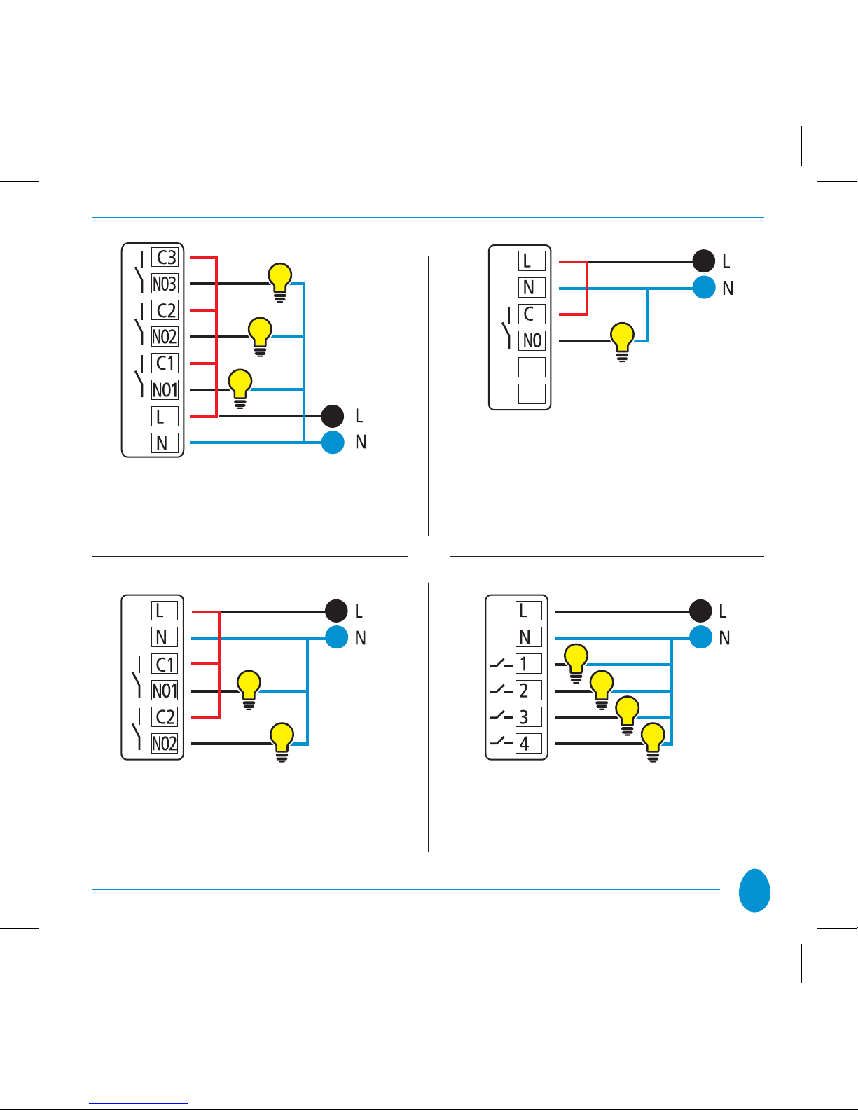
1. ELECTRICAL CONNECTIONS
Simply connect the Live wire to the terminal marked “L”, the Neutral wire to the
terminal marked “N” and the light(s) to the terminal(s) marked “NO1...NO3”.
All the relays function as switches, and the contacts are normally open. The units are
supplied complete with the jumpers marked on the diagram in red for connection
of terminals “C1...C3”. The device may be set to operate as a “Button” as well as
a “Switch”.
On-off Wireless
1 channel EU
On-off Wireless
2 channels EU
5
On-off Wireless
3 channels EU
On-off Wireless
1 channel BS
On-off Wireless
2 channels BS
On-off Wireless
4 channels BS

6
The circuit diagram below shows how to connect without the use of the jumper in
order to replace a button which controls a step relay for control of an existing lighting
system:
Step Relay
Button
to replace

7
IMPORTANT
After connecting, check that the wires are correctly positioned inside the
wall-mounting box. When securing Vitrum to the wall-mounting box, use
the screws supplied but do not use electric screwdrivers, as these may
exert excessive force which might damage the product.
8
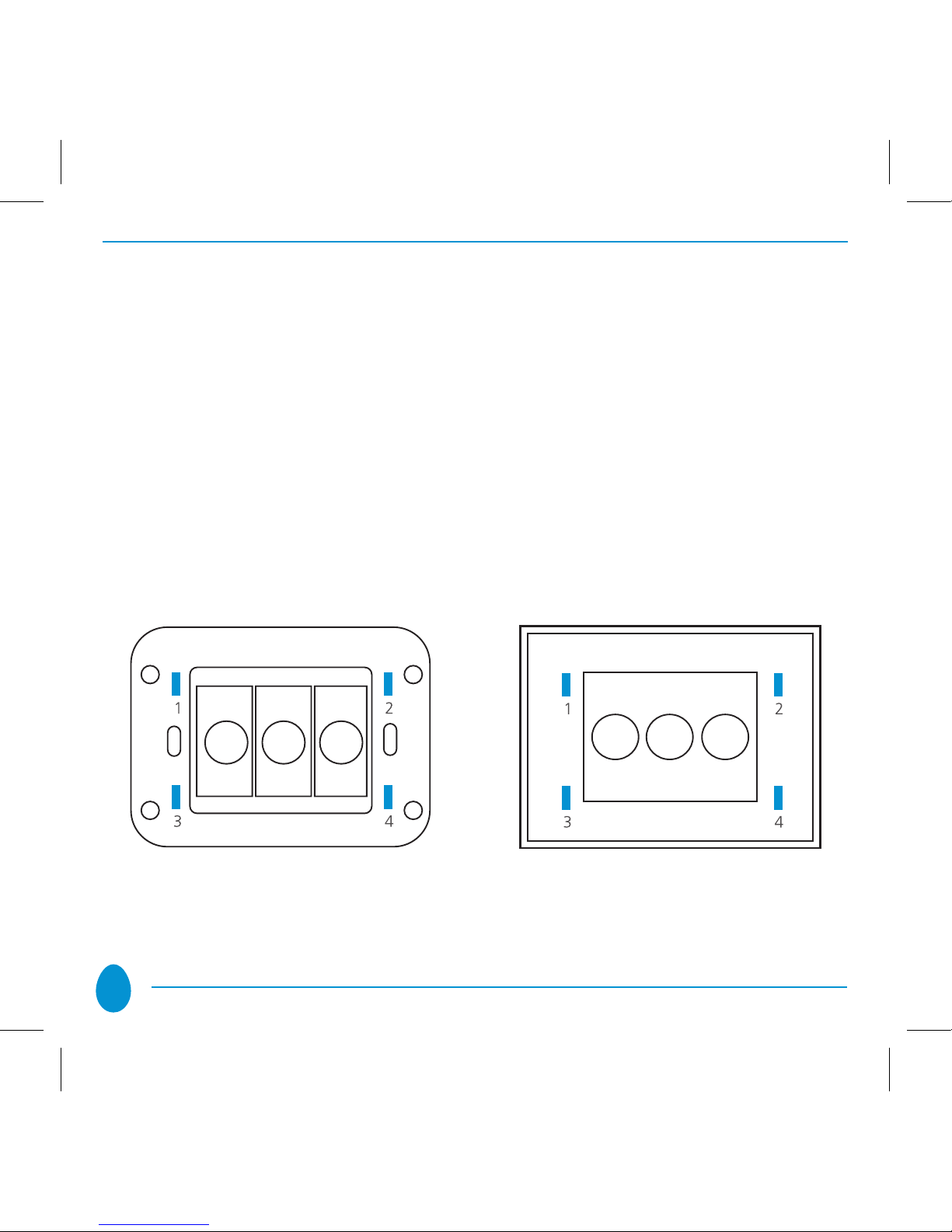
2. POSITIONING THE GLASS DECOR PANEL
In order to refit the glass panel correctly, ensure that the four plastic tabs on the
panel are in perfect alignment with the anchor holes. When the glass panel tabs
are aligned with the holes, press the four corners of the glass panel evenly until it
is fully inserted into the wall-mounting box.
After fitting the glass panel, the buttons remain inoperative for about 10 seconds.
An acoustic signal sounds three times to indicate that the sensors have been re-
calibrated, after which they resume normal operation. To remove the glass panel
from the wall-mounting box, gently lever the upper or lower edge away.
Anchor holes on electronic section Anchor tabs on décor panel

9
1A
B
C
D
2
3
4
3. VITRUM IS INTELLIGENT
The product that you have purchased functions INDEPENDENTLY, but it also has
a hi-tech “Wireless” technological heart. Thanks to “Z-Wave” Wireless technology,
each Vitrum Wireless unit offers numerous advantages if connected as part of a
network: it is possible to associate multiple Vitrum units, to construct scenarios,
and to control lights using a remote control unit. If you connect Vitrum into a pre-
existing z-wave net working with third parts devices, please refer to instruction and
procedure of your remote control. Otherwise proceed as follows to include Vitrum
to your Home Wireless Network:
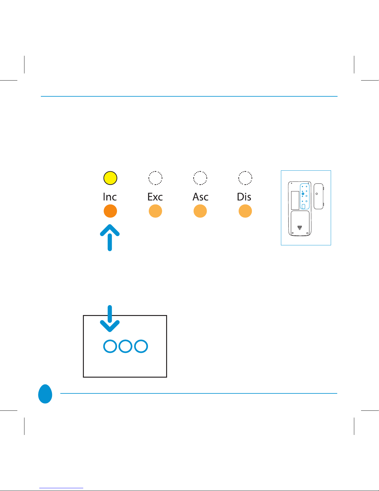
Open the rear panel of the• HOME MASTER remote handset.
10
Press and hold down• “INC” until the corresponding LED turns yellow, then
release the button.
Place the• HOME MASTER remote handset near the Vitrum unit to be included
in the network. Touch any of the keys on Vitrum to include the unit in the home
wireless network.
Vitrum indicates that it has
been connected to the network
by flashing the yellow LEDs three
times and switching on all the
lights connected to the unit.

11
When all the Vitrum units have been added to the network, press the• “INC”
key again until the LED switches off. Now you will see that the illuminated rings
around the Vitrum touch keys no longer light red when changing from one
status to the next.
NOTE
A Vitrum unit cannot be added to the network if it has already been included
in a different network. In this case, it is necessary to perform the factory reset
procedure > see Paragraph 6.
12
4. CONFIGURATION OF THE TYPE OF SWITCH
Vitrum is configured to operate as a normal ON/OFF switch (i.e. to ‘toggle’ the
ON and OFF status with each touch). The individual channels can be configured
as simple buttons. To do so, proceed as follows:
Remove the glass décor panel.•
Press and hold down the• two service touch keys for at least 8 seconds and
wait until the BEEP sounds twice to indicate that the system has entered the
configuration MENU. The LEDs in the touch keys will begin to flash either
blue or red, depending on the setting entered. The default setting for the
flashing light is blue since the factory setting is Switch.

13
Press each of the Vitrum touch keys briefly to select the•
desired operating mode.
FLASHING BLUE
Switch
Each time the touch key is pressed, the cyclic status is ‘toggled’:
Switch -> Button -> Switch …
FLASHING RED
Button
14
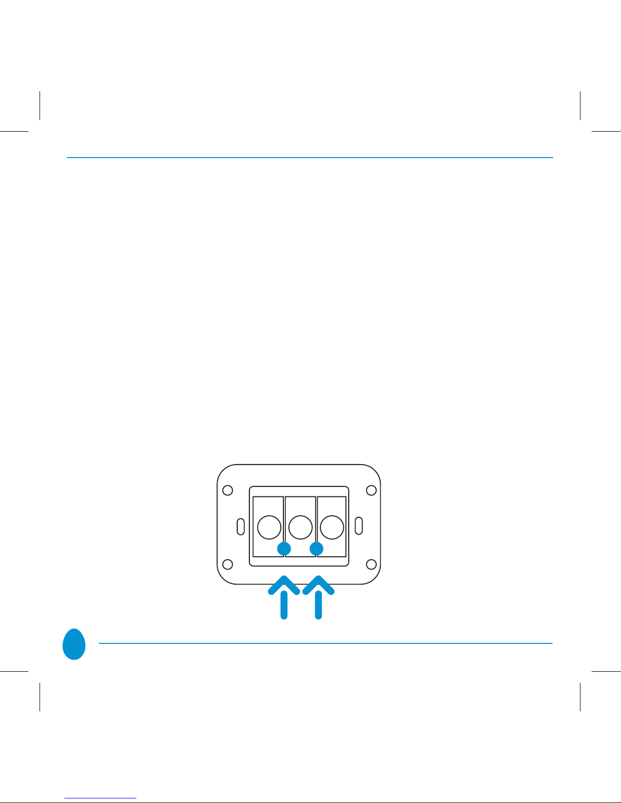
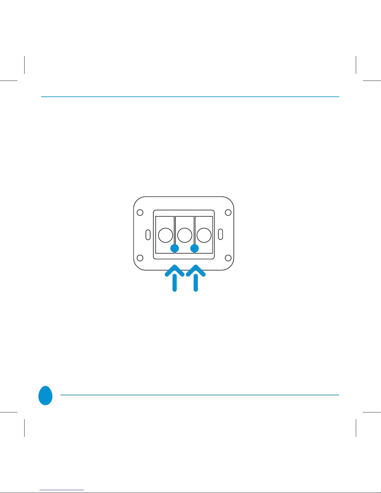
Vitrum returns to normal operation after 12 seconds of inactivity or if the two service
touch keys indicated by the yellow arrows in the figure below are pressed briefly
(0.5 seconds).
IMPORTANT
The default operating mode is “Switch”.

15
5.
ADVANCED FUNCTIONS: CREATION OF CONTROL LOGIC
On all Vitrum Wireless units, it is possible to create control logic processes that
associate the button on one Vitrum module to other buttons on OTHER Vitrum
modules (up to a maximum of five). Every Vitrum Wireless On-Off supports a
number of groups equal to the number of the device’s channels (=device’s buttons);
every single button/channel of a Vitrum has its own association group. Every group
supports up to 5 nodes (max 4 endpoint per node).
For creating a control logic, the modules must first be included in the home wireless
network (see paragraph 3). Then proceed as follows:
Set the HOME MASTER remote handset to• association mode by pressing and
holding down the “ASC” button until the YELLOW LED lights. Then release the
“ASC” button.

16
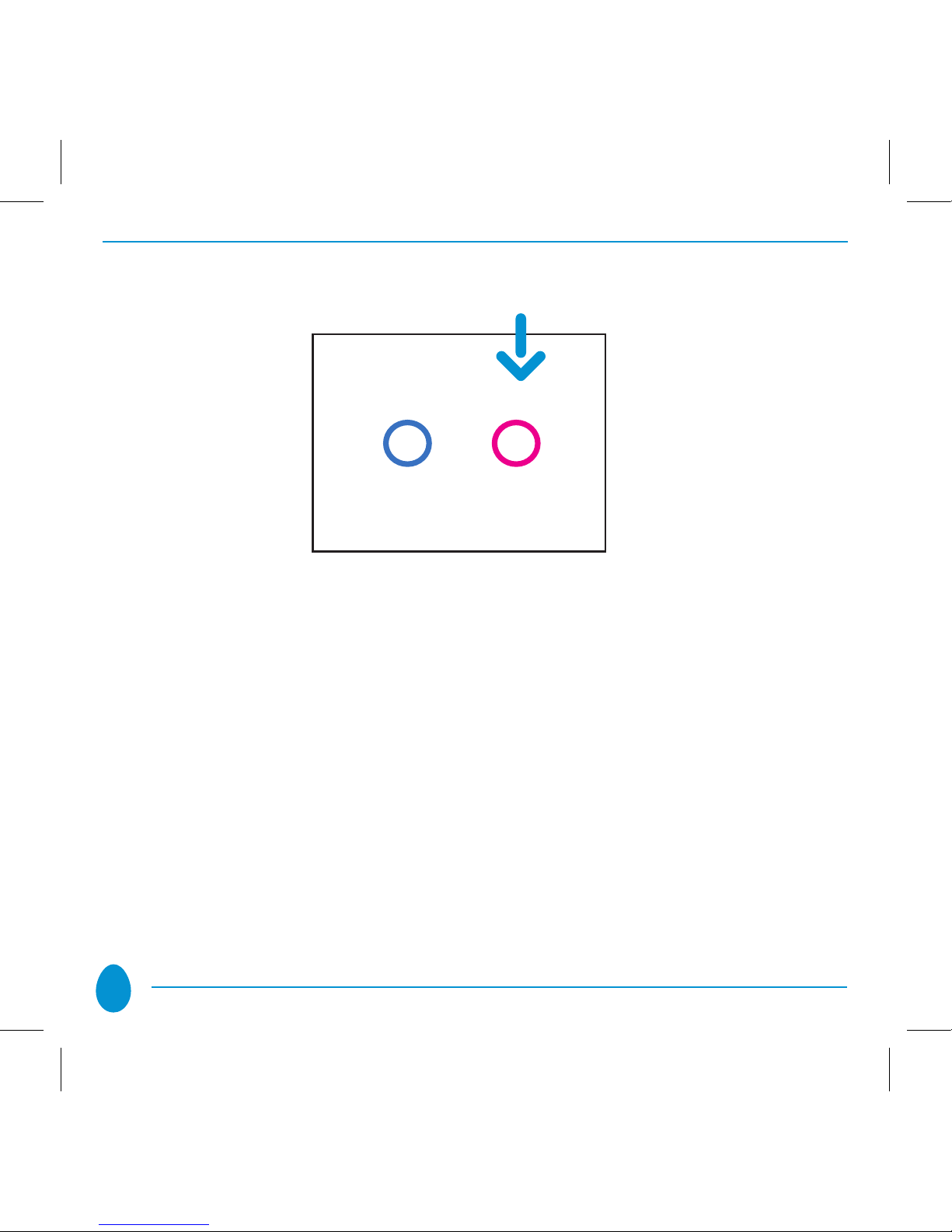
Press the button corresponding to the button/channel of the Vitrum unit to which•
the lights to be controlled are physically connected. The LED corresponding to
the selected button/channel will flash magenta until the ‘association’ process has
been completed. The user may select up to a maximum of FIVE buttons/channels
on different Vitrum modules.

17
Press the touch key on the Vitrum unit from which to control the lights connected•
to the buttons/channels of the Vitrum device(s) that have been selected previously.
In this case, too, the corresponding LED will light magenta.
On the HOME MASTER remote handset, press the ‘association’ touch key briefly.•
The LED will light red.
18
When carrying out these operations, it is necessary to position the remote
handset in the vicinity of the wall units.
IMPORTANT
Associations are possible only between separate Vitrum modules. It is not possible
to control more than one channel of a Vitrum device using a single touch key on
the same Vitrum unit. A touch key on a Vitrum device can be associated with a
maximum of 5 touch keys on other devices.
In order to cancel associations that have been entered, simply perform the same procedure,
though pressing the “DIS” key on the HOME MASTER remote handset instead of “ASC”.

19
6. FACTORY RESET
Proceed as follows to reset the Vitrum unit to the original factory settings:
A. EXCLUSION from the home network using the HOME MASTER remote handset:
Press• “EXC” on the HOME MASTER remote handset and wait until the
yellow LED lights.
Press and hold down the leftmost touch key on the multi-channel Vitrum•
unit (EU Standard), or the topmost key (BS Standard), or the central key
on single-channel units, for at least 8 seconds.

20
Vitrum will flash red three times and sound an acoustic signal to indicate•
that the original factory setting has been restored.
B. FACTORY RESET a.using the hidden button
Remove the Vitrum unit from the wall-mounting box.•
Press the hidden Factory Reset button and hold down for at least 3 seconds.•
Vitrum will flash red three times and sound an acoustic signal to indicate
that the original factory setting has been restored.
Table of contents
Other Vitrum Home Automation manuals


