Vivreau V3-204 User manual

1
V3-204 and 205 Dispensing Systems
Service Manual

2 3
Table of contents
Safety Precautions .......... ...................................................................3
General Information..............................................................................4
Technical Specications......................................................................5
Installation.............................................................................................7
Operating Instructions.........................................................................13
Maintenance........................................................................................15
Troubleshooting..................................................................................23
Illustrated Parts List............................................................................33
Wiring Diagrams..................................................................................36
© 2020 Vivreau Water Systems
All rights reserved.
Any and all information contained within this document is subject to
change without prior notice.
IMPORTANT ______________
The information contained in this manual is
specific to your system. It is IMPORTANT
you READ, FOLLOW and UNDERSTAND the
instructions given.
This manual and all material provided with your
system should be retained in a convenient location
for future reference.
Contact Vivreau if you have any questions
regarding the information contained in this
manual.
Safety precautions
IMPORTANT ________________________
This manual is intended for use by qualified
installers and service technicians only.
WARNING
Improper installation, adjustment,
alteration, service or maintenance can cause
property damage, injury, or death. Read the
installation, operating, and maintenance
instructions thoroughly before installing or
servicing this equipment.
WARNING
Keep the area around the unit
clear of any combustible materials.
WARNING
Do not store or use gasoline
or other flammable vapors or liquids in the
vicinity of this or any other unit.
IMPORTANT ________________________
Carefully read, understand and follow all safety
instructions in this manual and safety labels
on the unit.
• Keep safety labels in good condition and
replace missing or damaged items.
• Learn how to operate the unit and how to use
the controls properly.
• Do not let anyone operate the unit without
proper training. This unit is intended for use by
authorized personnel only.
• In the event of a power failure, do not attempt to
operate this unit.
• Keep unit in proper working condition and do
not allow unauthorized modications to the unit.
WARNING
Only trained and certied electrical,
plumbing and refrigeration technicians should
service this unit.
WARNING
ALL WIRING AND PLUMBING
MUST CONFORM TO NATIONAL AND LOCAL
CODES. FAILURE TO COMPLY COULD RESULT
IN SERIOUS INJURY, DEATH OR EQUIPMENT
DAMAGE.
SAFETY PRECAUTIONS ________________
This unit has been specifically designed to
provide protection against personal injury.
To ensure continued protection, observe
the following:
WARNING
Disconnect power to the unit
before servicing. Follow all LOCKOUT/TAGOUT
procedures. Verify power to the unit is OFF and
disconnected before any work is performed.
Failure to do so could result in serious injury,
death or equipment damage.
• To protect against electric shock, do not
immerse power cord in water or other liquid.
• To prevent damage to the power cord, do not
allow cord to hang over the edge of a table or
counter, or come in contact with hot surfaces.
• Isolate unit from power supply (unplug or turn
OFF breaker) and turn OFF the water supply
when not in use and before cleaning.
• Allow Boiler (if supplied) to cool before
removing any components.
• The use of spare parts and accessories not
recommended by Vivreau may cause damage
and/or injuries.
• Do not operate any unit with damaged cords,
plugs, or after the unit malfunctions or has
been damaged in any manner.
• Do not use outdoors.
• Do not place on or near a hot gas or electric
burner.
• Do not use the unit for anything other than its
intended use.
• Save these instructions.

4 5
INFORMATION FOR THE READER
To nd specic topics of interest quickly, refer
to the Table of Contents at the beginning of this
manual.
This manual is solely for the use of qualied
installers and service technicians.
PURPOSE OF THE MANUAL
• Vivreau has produced this manual to provide
necessary information to qualied and
authorized personnel for the safe and proper
installation, operation, maintenance, and
servicing of the Vivreau V3-204 and V3-205
Dispensing Systems.
• Information contained in this manual will help
prevent risks to health and safety, and the risk
of economic losses.
• Keep this manual in a clearly identied and safe
place throughout the working life of the unit, so
that it will always be available as needed.
• The manufacturer reserves the right to make
modications to the unit without any obligation
to provide prior notice.
• A number of symbols have been used to
highlight particularly important parts of the text
or important specications. Their meaning is as
dened below.
WARNING
Indicates that suitable procedures must be
adopted to avoid putting people’s health and
safety at risk or causing economic losses.
CAUTION
Indicates a potentially hazardous situation
which, if not avoided, may result in property
damage, minor or moderate injury.
IMPORTANT ________________________
Indicates important technical information
which
must not
be overlooked.
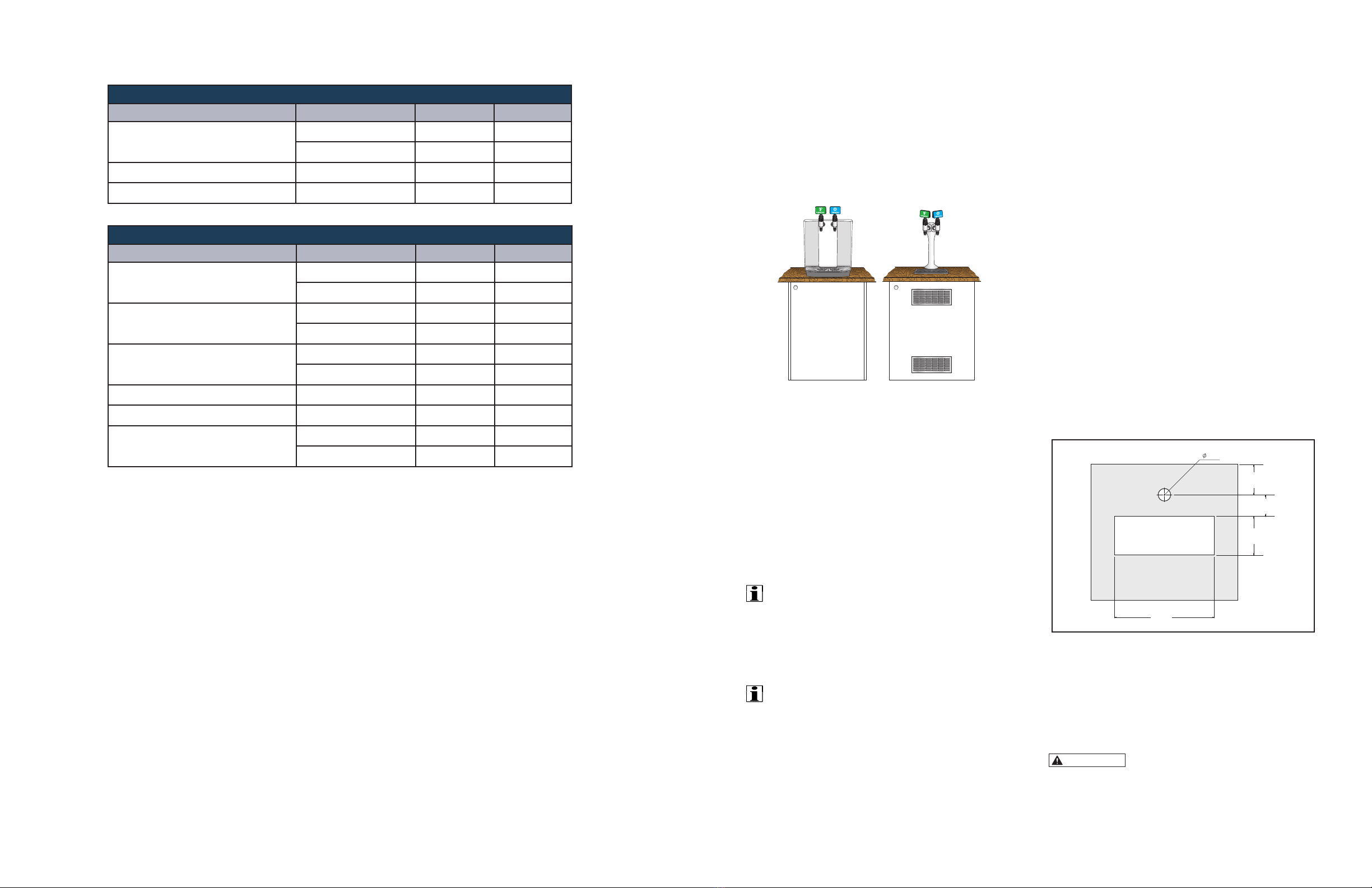
Technical SpecicationsGeneral Information
GENERAL DESCRIPTION
The Vivreau V3-204 and V3-205 Dispensing Systems
are designed to provide Chilled Still and Sparkling
Water on demand.
Model V3-204 is a Water Dispensing System designed
for countertop installation with the CO2Cylinder, CO2
Regulator and Water Filter mounted in a cabinet below
the unit.
Model V3-205 is a Self-Service Water Dispensing
System designed for under-counter installation with
the Dispenser Head mounted to the countertop
directly above the unit.
Each unit can be connected to a bulk CO2system, in
lieu of a CO2Cylinder and regulator.
Both systems are made up of several components
that will t under a standard minimum 24” wide base-
cabinet section.
Performance is the same for both models and
selection is based on space available for installation.
The system has been designed for operation at
ambient temperatures up to 90ºF.
Dispensing Specications
Description Specication V3-204 V3-205
Chilled still water ΔT=18 °F @ 15.8 gal/h ü ü
Chilled sparkling water ΔT=18 °F @ 15.8 gal/h ü ü
Water Pressure at Dispensing Head 5 PSI ü ü
Operating Conditions
Description Specication V3-204 V3-205
Temperature 60 – 90°F ü ü
Relative Humidity 60% (max.) ü ü
Water Supply Requirements
Description Requirements V3-204 V3-205
1/2” FNPT connection with Ball Valve 1/2” ü ü
PSI (min.) 50 ü ü
GPH (min.) 80 ü ü
Temperature (max.) 60°F ü ü
CO2Operating Pressure
Description Requirements V3-204 V3-205
Pressure 65-70 PSI ü ü
Supply Pressure (Bulk System) 100 PSI (min.) ü ü
6 7
Installation
INTRODUCTION
The Vivreau V3-204 and V3-205 Dispensing
Systems are countertop and under-counter Water
Dispensing Systems. Chilled water is available
from Dispensers that provide Still and Carbonated
Water from individual faucets.
Vivreau V3-204 and V3-205 Dispensing Systems
PRE-INSTALLATION
Below are the services required to be in place
prior to the installation of the Vivreau V3-204 or V3-
205 Dispensing System. If you have any questions
regarding these or other services, please contact
Vivreau Service Toll-Free at 877-999-1044.
WATER SUPPLY
One (1) potable 1/2” cold water supply terminating in
a 1/2” NPT Ball Valve, 1/2” female pipe thread.
IMPORTANT ________________________
Ball Valve must be accessible for service and
installation.
Minimum Water Pressure: 50 PSI
Minimum Water Flow: 80 gallons per hour
IMPORTANT ________________________
The Vivreau V3-204 and V3-205 Dispensing
System incorporates back-ow prevention. Any
additional back-ow devices required by Federal,
State or Local Code must also be supplied by the
customer prior to installation. There must not be
any other Filters/Pre-Filters inline before the unit.
ELECTRICAL OUTLET
Model V3-204 and V3-205
(1) 20 Amp Electrical Circuit (NEMA 5-20R) 120V,
60 Hz (8 Amps)
CO2
CO2Cylinder (Customer supplied) - Size should
be selected based on available space. A 20 lb.
cylinder is typical.
NOTE: If connecting to a bulk or existing CO2
system, a CO2 line terminating at a 1/4” Barbed
Shutoff Valve must be available within 40” of the
unit with 100 PSI minimum pressure.
DRIP TRAY AND DISPENSING HEAD
CUTOUTS (Model V3-205 Only)
Cut out the holes for the Drip Tray and Dispensing
Head per the supplied template.
NOTE: The Dispensing Head must be mounted
on the work surface directly above the Chiller/
Carbonator.
15/8"
27/8"
37/8"51/8"
121/8"
Dispensing Head Dimensions
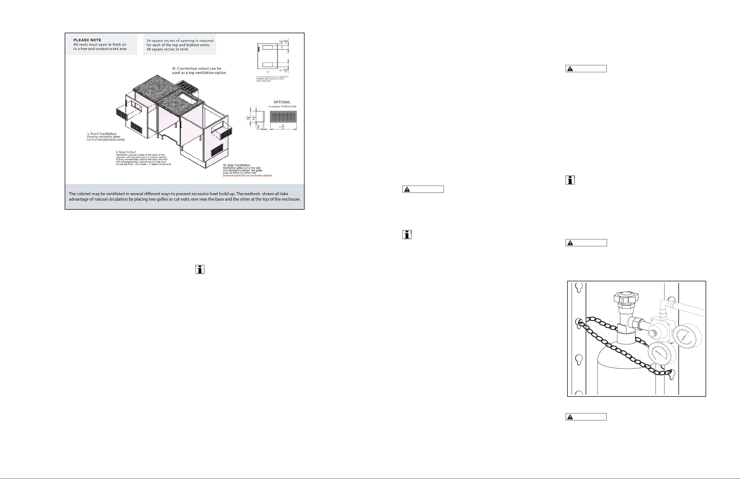
VENTILATION
If the system is to be installed in an enclosed space or
in a cabinet, adequate ventilation must be provided.
Countertop units require a 1” minimum clearance on
each side for proper ventilation.
CAUTION
Failure to provide adequate
ventilation will cause system failure.
This unit is to be installed indoors only.
Cooler/Carbonator Specications
Description Specication V3-204 V3-205
Width
14.7” ü—
14.2” —ü
Height
21.3” ü—
18.5” —ü
Depth
19.5” ü—
17” —ü
Weight 72.6 lbs. üNA
Voltage 110/120 VAC/60 Hz ü ü
Amperage
8A ü—
11A —ü
Dispenser Head Specications
Description Requirements V3-204 V3-205
Height
21.25” ü—
19.3” —ü
Distance Nozzle to Drip Tray 12.3” ü ü
Weight 7.4 lbs. NA ü
NA = Not Available
8 9
LOCATION OF SERVICES
All services must be accessible for installation
and service. Ensure all services are kept within 40”
of the V3-204 and V3-205 Dispensing Systems.
Water Shutoff Valve to be located at low level.
Ensure there is sufcient room for a 6” long tting to
be connected to the Water Shutoff Valve.
Top of drain should be located between 12” and
18” from oor level.
SHIPPING DAMAGE/MISSING PARTS
Unpack and inspect the unit for shipping damage
and/or missing parts. If any damage or missing
parts are found, contact Vivreau Service Toll-
Free at 877-999-1044 and report the missing or
damaged parts.
INSTALLER’S CHECKLIST
Below are the services required to be in place
prior to the installation of the Vivreau Dispensing
System. Please review and check all services
before beginning work. If anything is missing
or not correct, do not start the installation. Call
Vivreau Service for instructions at 877-999-1044.
WATER SUPPLY
A potable 1/2” cold water supply terminating in a
1/2” Ball Valve, 1/2” female pipe thread.
IMPORTANT ________________________
Ball Valve must be accessible for service and
installation.
Any water line or valve less than 1/2” is not
acceptable. Must be a direct supply with no
other Inline Filters.
ELECTRICAL OUTLET(S)
All Electrical Outlets must be within 40” of unit. No
Extension Cords.
Model V3-204 and V3-205
(1) 20 Amp Electrical Circuit (NEMA 5-20R) 120V,
60 Hz (8 Amps)
CO2
CO2 Cylinder (Customer supplied) must t within
the allotted space.
CO2Cylinder must always remain vertical.
If connecting to a bulk or existing CO2system, a
CO2 line terminating at a 1/4” Barbed Shutoff Valve
must be available within 40” of the unit with 100
PSI minimum pressure.
DRIP TRAY AND DISPENSING HEAD
CUTOUTS (Model V3-205 Only)
For under-counter units, cut out the holes for the Drip
Tray and Dispensing Head per the template.
The Dispensing Head must be mounted on the work
surface directly above the Chiller/Carbonator.
The Dispensing Head lines must never be extended.
DRIP TRAY DRAIN (Model V3-205 Only)
Drip Tray must be plumbed to a drain. Customer
will need to supply a properly trapped drain
according to Federal, State and Local Codes. The
drain must be large enough to accommodate a 1”
OD exible pipe.
VENTILATION
If the system is to be installed in an enclosed
space or in a cabinet, adequate ventilation must
be provided.
CAUTION
Failure to provide adequate
ventilation will cause system failure.
This unit is to be installed indoors only.
INSTALLATION
IMPORTANT ________________________
Installation must be performed by properly trained
and qualied persons and comply with Federal,
State and Local Codes for connection to electrical
supplies, water supplies and pressurized gas
systems.
Note: Vivreau cannot be held responsible for any
damage caused by improper installation.
LOCATION
A completed Pre-installation Checklist must be
available prior to installation. The Vivreau Dispensing
System must be installed indoors where the ambient air
temperature will not exceed 90°F.
The Vivreau Dispensing System should not be
exposed to spills, spray, steam or high humidity.
A suitable location should be chosen within 40” of
the electrical and water supply connections.
Vivreau Model V3-204 is designed to be installed with a
minimum 1” clearance on the left and right sides.
Allow adequate space in the rear of the unit for
connections. This will allow for proper ventilation.
Vivreau Model V3-205 is designed to be installed
in an under-counter cabinet with adequate
ventilation for component cooling.
Do not obstruct air vents.
Install the system on a rm, level oor or base.
CONNECTIONS
WARNING
This unit must be electrically
grounded.
ELECTRICAL
Power Supply: 120V 60Hz
Power Supply Connection Type: NEMA 5-20 plug
Grounded, with proper circuit protection.
CO2
Mount the CO2Regulator in a secure location
where it will not be subject to damage.
A Cylinder of food-grade CO2gas is required. Only
use non-syphon type Cylinders.
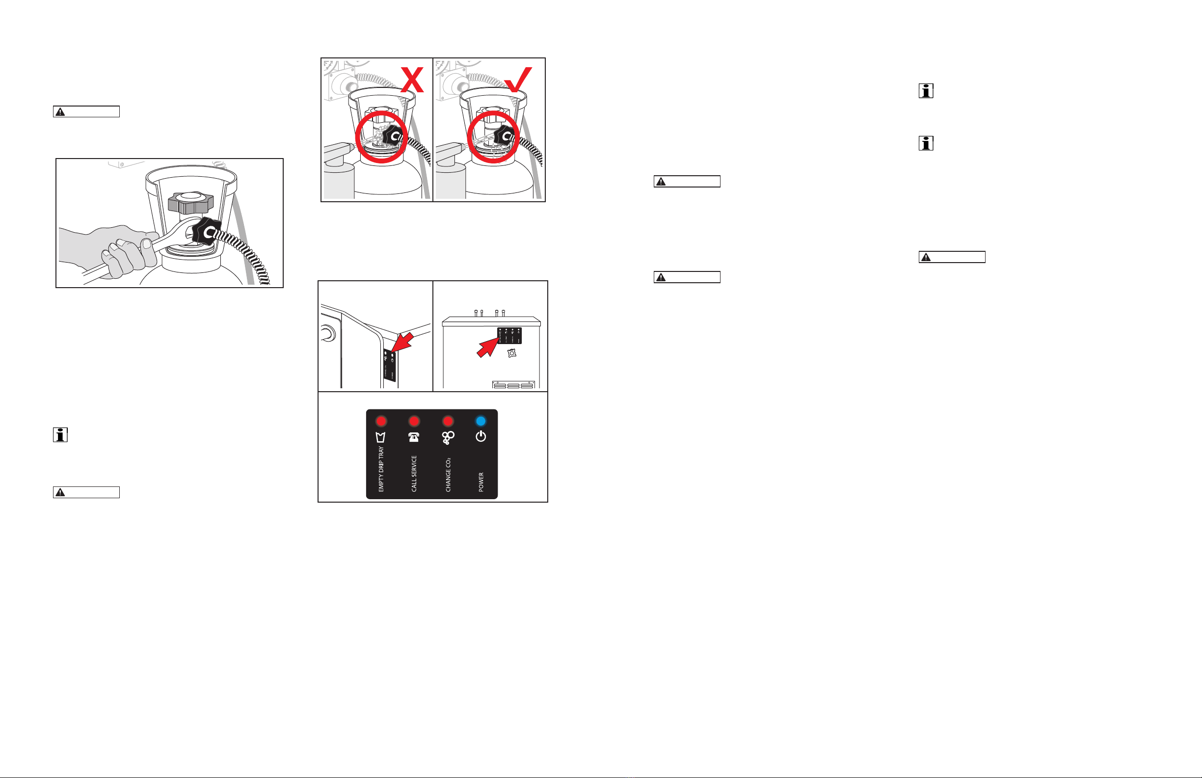
IMPORTANT ________________________
Before connecting, with the Cylinder Outlet
turned away, open Valve for short blast and
close immediately. This will clear any debris
from the outlet.
CO2Cylinder must be installed vertically and
secured with a Chain, Strap or Bracket.
CAUTION
CO2Cylinders should always be
secured in the vertical position with the Outlet
Valves positioned at the top. This will help
prevent injury caused by the entry of liquid
Carbon Dioxide into the Pressure Regulator.
CO2Cylinder Installation
WARNING
Never open the Gas Cylinder
Valve without the Gas Regulator installed.
Ventilation Options

10 11
Ensure the Sealing Washers are positioned
between the Gas Regulator / Regulator Hose and
Cylinder and connect the Cylinder.
Regulator
Sealing
Washers
CO2Cylinder
Sealing Washer Locations
Connect the Regulator to the unit using the supplied
Installation Kit. Tighten all connections.
In the event of a CO2leak, close the Cylinder Valve,
retighten connection(s) and retest. If leak persists,
report leak to Vivreau.
CO2Pressure: 65 - 70 PSI. Adjust Regulator as
needed.
WATER
The Vivreau V3-204 andV3-205 DispensingSystems
provide back-flow prevention, however, it must
be installed with adequate back-flow protection to
comply with applicable Federal, State and Local
Codes. Additional back-flow prevention must be
installed prior to connecting the unit to the water
supply.
The water supply to the unit must be cold, potable
water with an accessible Shutoff Valve.
Water connection to the supply is 1/2” FNPT.
Water Inlet connection to the unit is 3/8” tube. A
Retaining Clip must be used to attach the tube to
the connection on the unit.
CO2
In
Still
Out
Sparkling
Out
Water In
From Filter
V3-205V3-204
Retaining Clip
Water
Connection
CO2
Connection
Connecting Water Supply
Insulate the pipe to prevent condensation.
The supply water pressure must be 50 PSI minimum
with a minimum ow of 1.5 gal/min. A Booster Pump
(for low pressure) or Pressure Regulator (for high
pressure) may be required to ensure the pressure.
IMPORTANT ________________________
Only connect water supply to the unit after
filling the Internal Water Tank with the water
supply line.
DISPENSING HEAD
The Dispensing Heads for Model V3-204 come
assembled and connected to the front of the unit.
Assemble and mount Dispensing Heads for Model
V3-205, making sure Dispensers are tight and
straight.
V3-205V3-204
V3-204 and V3-205 Dispensing Heads
COUNTERTOP INSTALLATION
(Model V3-204)
Place the unit on a at, level surface; use adjustable
feet to level if necessary.
Position Drip Tray beneath Dispensers.
Mount Filter Head nearby (under-counter cabinet,
rear wall, etc.) and secure.
Select a location for the CO2Cylinder where it can
be secured in an upright position.
UNDER-COUNTER INSTALLATION (Model
V3-205)
The Under-Counter Cooler/Carbonator System
is intended to be located directly under the
Dispensing Head.
The Drip Tray is positioned in the counter under
the Dispensing Head and should have lateral play
of no more than 1/8”.
Dispensing Head Connection Tubes are to be
build-up.
connected to the Under-Counter System directly
using the Installation Kit supplied by Vivreau.
Adequate ventilation must be provided in under-
counter installations to prevent excessive heat
build-up.
DRIP TRAY DRAIN (MODEL V3-205 ONLY)
Connect exible hose to Drip Tray Drain Fitting and
route to existing drain. Drain should be a Stand-
Pipe with a trap, 1.25” diameter.
FILLING THE WATER TANK
WARNING
Disconnect unit from electrical
power supply.
Before making the nal water connection to the unit:
Remove the Overow Plug, located on the Rear Panel on
Model V3-204 and Front Panel on Model V3-205.
Prop the side opposite the Overow Plug up about 1”.
Slowly ll the Water Tank using the Water Supply Line.
Catch any water that overows.
Remove
Overflow
Drain
Tube Plug
Water
Supply
Line
Drain Overow
Level the unit.
Replace the plug.
Connect Water Supply Line to unit.
Clean up any spills.
CAUTION
Do not leave the Water Hose
unattended while filling.
Make sure no water spills onto electrical
components.
Unless approved by Vivreau, do not use de-ionized
water or add any substance to the water.
CAUTION
The installer must stay on site
until a full icebank has formed. Water will be
displaced and exit from the overflow.
CONNECTING THE CO2
Ensure both Dispensers are in the closed
(UP) position.
Open the units door for access and connect the CO2
Regulator to the CO2Cylinder or bulk system. Ensure
the Sealing Washer is used for each connection.
V3-205
Regulator
CO2tank
Sealing
Washers
Connect the CO2Cyliner
Open the CO2 Cylinder Valve or turn ON bulk CO2
supply and check for leaks.
Set Regulator Pressure to 65 - 70 PSI.
CARBONATOR BOWL ACCESS
To access the Carbonator Bowl, remove the two (2)
Screws across the rear of the Top Panel and remove
panel.
Top Panel Removal s

12 13
Carbonator
Bowl
Carbonator Bowl Location
Vent the Carbonator Bowl for two (2) seconds. To
do this, lift the Carbonator Relief Valve located on
the Carbonator Bowl.
Carbonator Relief Valve Location
Make sure adequate Water Supply Pressure of 50
PSI minimum is present.
Connect the water supply to the Inlet Fitting on the
rear of the unit.
Secure with a Retaining Clip, and turn ON the
water.
Replace Back and Service Panels, Clamp and
Panel Screws.
Plug in the Power Cord to the electrical outlet.
Proceed with sanitizing the water system. Follow
Vivreau Sanitizing Process Instructions.
IMPORTANT ________________________
The Sanitizing and Filter Change Procedure
should only be performed by qualified and
authorized personnel.
After sanitizing, unplug unit. Remove Back and
Service Panel, and install the normal service Filter
Cartridge.
Reinstall Back and Service Panels and plug in unit.
Dispense two (2) gallons of water through each
Dispenser, Still and Sparking, to ush all Sanitizing
Solution from system.
Flushing the Sanitizing Solution
(Model V3-205 Shown)
Taste test samples from each Dispenser. Continue
to ush, if needed.
unit is ready for service.
Fill out Installation Checklist and return to Vivreau..
DISPENSING
Before operating either the Vivreau V3-204 or
V3-205 Dispensing System, make sure the Water
Supply Valve is open and the unit is plugged in.
Place appropriate container on Drip Tray beneath
Dispensing Head.
Chilled Still Water
Pull DOWN on Blue Dispenser Handle. Push
Dispenser Handle UP when full.
Dispensing Chilled Still Water (Model V3-205 Shown)
Chilled Sparkling Water
Pull DOWN on Green Dispenser Handle. Push
Dispenser Handle UP when full.
Dispensing Chilled Sparkling Water
(Model V3-205 Shown)
The Dispenser Handles should be fully opened
when filling and fully closed when filling is
complete.
IMPORTANT ________________________
Do not allow the Dispenser Handles to slam shut.
The Dispenser Handles must be closed after each
Bottle is lled.
The Vivreau V3-204 and V3-205 Dispensing Systems
are designed to ll Bottles of up to one (1) liter, one
Bottle at a time.
Vivreau Bottles should be lled to the line in the
neck just below the Cap.
IMPORTANT ________________________
Sparkling Water requires room for the CO2gas
to expand.
At the end of service, remove the Black Dispenser
Nozzles and soak in Sanitizing Solution.
The Dispensers and unit should be wiped down
with Sanitizing Solution to keep the Dispensing
System clean and in hygienic condition.
Once the unit is wiped down and Nozzles removed,
both Dispensers must be wrapped in plastic wrap
to prevent contamination and misuse while not in
service.
To return the Vivreau V3-204 or V3-205 Dispensing
System to service, remove all plastic wrap and rinse
Dispenser Nozzles.
Reinstall the Nozzles into the Dispenser Head.
CHANGING A CO2CYLINDER
WARNING
Wear protective gloves and
safety glasses when changing CO2Cylinders.
Close the Valve on top of the empty Cylinder.
Close Empty Cylinder Valve
Operating Instructions
14 15
Using the proper wrench, loosen the Nut on the
Cylinder to disconnect the High-Pressure Hose or
Primary Regulator. Allow residual gas to escape
from the hose.
WARNING
The line is pressurized.
Pressure will be released while performing this
procedure. Handle carefully.
Disconnect High-Pressure Hose
Place the Regulator within safe reach.
SECURE CYLINDER
Move empty Cylinder to storage area and secure
safely.
Remove the plastic plug or tape from the new full
Cylinder outlet and discard it.
IMPORTANT ________________________
To avoid confusion, do not replace plastic
plugs in the outlet of empty CO2Cylinders.
WARNING
Wear protective gloves and safety
glasses when purging Cylinder. Be sure to point
the Cylinder outlet away from your body.
Purge the replacement Cylinder by quickly opening
and closing the Valve on top to clear any dust or
moisture from the outlet.
Connect the High-Pressure Hose or Primary
Regulator. Make sure the Sealing Washer is seated
correctly.
Tighten the Nut rmly using a wrench.
Open the Valve on top of the Cylinder.
Check for leaks using a solution of soapy water or
a commercial equivalent.
Checking for Leaks
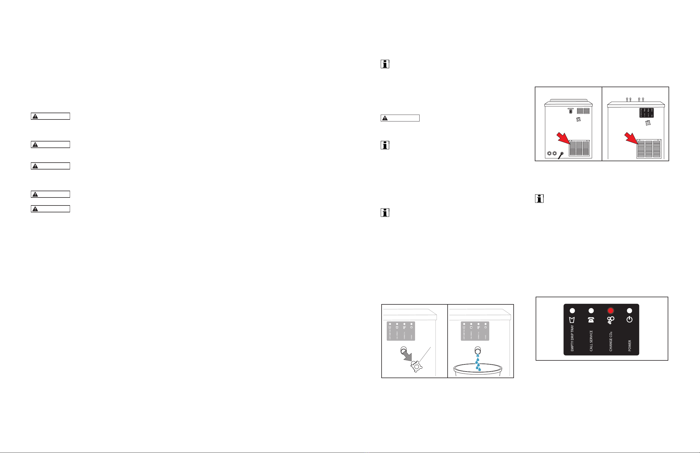
LED DISPLAY PANEL
The LED Display Panel indicates the status of the
unit and is located on the front panel of the unit.
V3-205V3-204
LED PANEL LIGHTS
LED Display Panel Location and Lights
POWER: When the Dispensing System is plugged
in and turned ON, a Blue LED will be illuminated.
CHANGE CO2: When the CO2supply is low, a Red
LED will illuminate and the unit will beep; alerting
you to change the CO2Cylinder.
CALL SERVICE: If there is a problem, a Red LED will
illuminate and the unit will beep. Please contact Vivreau
Service Toll-Free at 877-999-1044 immediately.
EMPTY DRIP TRAY (Not Activated on this unit):
When the Drip Tray Container is FULL, a Red LED will
illuminate and the unit will beep; alerting you to empty
the Drip Tray Container located just inside the cabinet
front door or below the Dispensing System.
MAINTENANCE RECOMMENDATIONS
Keep the unit at peak efciency by performing
all scheduled maintenance procedures that
are recommended by the manufacturer. Proper
maintenance will allow the best performance and a
longer working life.
WARNING
Before performing any service
procedure, perform all safety procedures. In
particular, turn OFF the water supply, disable
the electricity at the main circuit breaker
and prevent access to all devices that might
cause unexpected health and safety hazards
if turned ON.
WARNING
Before performing any service
that involves electrical connection or
disconnection and/or exposure to electrical
components, ALWAYS follow the Electrical
LOCKOUT/TAGOUT Procedure. Disconnect all
circuits. Failure to comply can cause property
damage, injury or death.
At the end of each day or whenever necessary, be sure
to clean:
• Dispensing Head/Nozzle
• Drip Tray
• The surrounding work area
Every year, have skilled, authorized personnel
perform the following operations:
• General check of the unit
• Identify and replace worn parts
IMPORTANT ________________________
Record all yearly inspections.
IMPORTANT ________________________
Contact the factory, the factory representative
or an authorized service agent to perform
maintenance and repairs.
ELECTRICAL LOCKOUT/TAGOUT
PROCEDURE
WARNING
Before performing any service
that involves electrical connection or
disconnection and/or exposure to electrical
components, ALWAYS follow the Electrical
LOCKOUT/TAGOUT Procedure. Disconnect all
circuits. Failure to comply can cause property
damage, injury or death.
The Electrical LOCKOUT/TAGOUT Procedure is
used to protect personnel working on an electrical
unit. Before performing any maintenance or service
that requires exposure to electrical components,
follow these steps:
In Electrical Box, place unit Circuit Breaker into
OFF position.
Place a lock or other device on the Electrical Box
Cover to prevent someone from placing Circuit
Breaker in the ON position.
Place a tag on Electrical Box Cover to indicate
that unit has been disconnected for service and
power should not be restored until tag is removed
by maintenance personnel.
Disconnect the unit’s Power Cord from Electrical
Outlet.
Place a tag on the Power Cord to indicate that the
unit has been disconnected for service and power
should not be restored until tag is removed by
maintenance personnel.
Maintenance
16 17
STAINLESS STEEL CARE
Cleaning
Stainless steel contains 70-80% iron, which will
rust if not properly maintained. It also contains 12-
30% chromium, which forms an invisible passive,
protective lm that shields against corrosion. If the
lm remains intact, the stainless steel will remain
intact. However, if the lm is damaged, the stainless
steel can break down and rust. To prevent stainless
steel breakdown, follow these steps:
CAUTION
Never use any metal tools. Scrapers,
les, wire brushes or scouring pads (except for
stainless steel scouring pads) will mar the surface.
CAUTION
Never use steel wool, which will
leave behind particles that rust.
CAUTION
Never use acid-based or
chloride-containing cleaning solutions, which
will break down the protective film.
CAUTION
Never rub in a circular motion.
CAUTION
Never leave any food products
or salt on the surface. Many foods are acidic.
Salt contains chloride.
For routine cleaning, use warm water, mild soap or
detergent and a sponge or soft cloth.
For heavy-duty cleaning, use warm water, a degreaser
and a plastic, stainless steel or Scotch-Brite pad.
Always rinse thoroughly.
Always rub gently in the direction of the steel grain.
Preserving & Restoring
Special stainless steel polishing cleaners can
preserve and restore the protective lm.
Preserve the life of stainless steel with a regular
application of a high quality stainless steel
polishing cleaner as a nal step to daily cleaning.
If signs of breakdown appear, restore the stainless
steel surface. First, thoroughly clean, rinse and
dry the surface. Then, on a daily basis, apply a
high-quality stainless steel polish according to
manufacturer’s instructions.
Heat Tint
Darkened areas, called heat tint, may appear on
stainless steel exposed to excessive heat, which
causes the protective lm to thicken. It is unsightly
but is not a sign of permanent damage.
To remove heat tint, follow the routine cleaning
procedure. Stubborn heat tint will require heavy-
duty cleaning.
To reduce heat tint, limit the exposure of equipment
to excessive heat.
DAILY CLEANING
The Vivreau V3-204 and V3-205 Dispensing
Systems should be cleaned once a day.
Vivreau recommends using disinfectant spray or a
sanitizing wipe for cleaning.
If the Dispensing Head becomes soiled with coffee,
tea, milk, etc., clean with hot soapy water using a
non-abrasive cloth.
Clean the Drip Tray Cover and inside the Drip Tray
using either disinfectant spray (non-chlorine) or
hot, soapy water and non-abrasive cloth.
Keep area around the unit clean and sanitized.
Viverau V3-204 and V3-205 Dispensing Systems
equipment in the under-counter area should be
kept free of dust; the ventilation should not be
obstructed restricting free air ow around the
equipment.
The VivreauV3-204 and V3-205 Dispensing Systems
Nozzles should be removed daily and cleaned with
hot soapy water and a non-abrasive cloth.
After completing all cleaning tasks, dispense water
for at least 10 seconds to ush through the Nozzle.
DO NOT use any abrasive material on your Vivreau
V3-204 or V3-205 Dispensing System.
SERVICE INFORMATION
The CO2Cylinder is located inside the cabinet
door.
IMPORTANT ________________________
Maintenance and repairs must only be
performed by qualified and trained personnel
and comply with Federal, State and Local
Codes for connection to electrical supplies,
water supplies and pressurized gas systems.
WARNING
Always electrically disconnect
the Vivreau system before removing covers or
carrying out any work.
IMPORTANT ________________________
If the unit malfunctions, develops a leak,
sustains physical damage or component
failure, UNPLUG THE POWER CORD.
If any maintenance or service is required, refer
to the troubleshooting chart, wiring diagram and
exploded parts drawings contained in this manual.
IMPORTANT ________________________
Only use Vivreau recommended spare parts
for cooler maintenance. Failure to do so will
invalidate cooler approvals and warranty.
MAINTENANCE
Chiller Unit
Check that the Water Level in the Tank is up to the
Overow Plug. Tip unit, if necessary, to observe
the Water Level.
Remove
Overflow
Drain
Tube Plug
Check Water Level
CONDENSER GRILLE
The Cooling System Condenser Grille should be
cleaned regularly, a minimum of every three (3)
months, with a vacuum cleaner or soft brush to
ensure the equipment can breathe. The Condenser
is located on the front of the unit behind the cabinet
door.
V3-205V3-204
Condenser Grille Location
CARBONATOR PUMP PROTECTION
IMPORTANT ________________________
The Carbon Vane Pump located on the
Carbonator Motor should never be run dry.
This will cause permanent damage to the unit.
To reduce this risk, the Controller has a timer
circuit that will automatically turn OFF the
Motor and Solenoid after running continuously
for approximately two (2) minutes.
If there is a problem, a Red LED will illuminate and
the unit will beep. Please contact Vivreau Service
Toll-Free at 877-999-1044 immediately.
LED Display Panel CALL SERVICE
18 19
WATER FILTRATION
Replace the Water Filter after 25,000 gallons or
every 6 months of use, whichever comes first.
Follow ALL Sanitizing and Filter Change Procedures.
SANITIZING AND FILTER CHANGE
WARNING
Make sure Do Not Use sign is
displayed throughout the entire sanitation
process.
WARNING
Always wear safety glasses
while handling the sanitizing chemicals.
Turn the main Water Supply OFF and unplug the
Power Cord.
To drain both Still and Sparkling Water, pull down
the Blue and Green Dispensing Handles until the
water stops.
Pull Down to Drain Still and Sparkling Water
(Model V3-205 Shown)
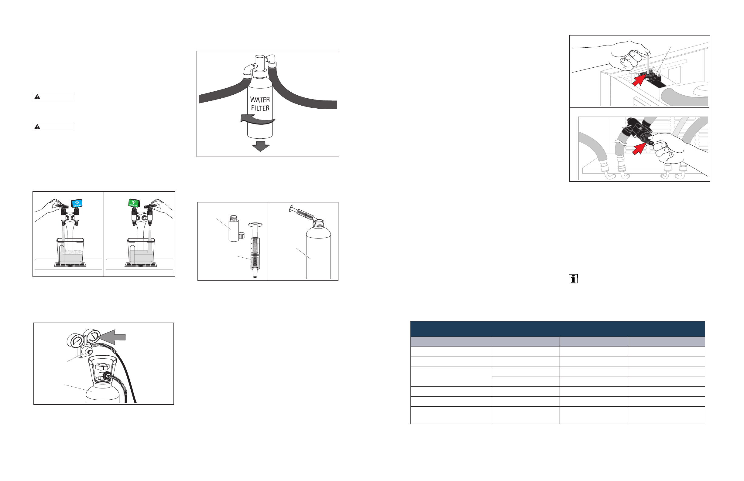
Conrm the proper CO2Pressure, 65 - 70 PSI, at
the Regulator and adjust if necessary.
Regulator
CO2Cylinder
CO2Pressure
65-70 PSI
Conrm CO2Pressure
Remove the old Filter Cartridge by turning counter-
clockwise and pulling down.
Remove Old Water Filter
Using the supplied Syringe, ll Sanitizing Cartridge
with 2ml (about 1/2 teaspoon) of Sanitizing Solution
and insert Sanitizing Cartridge into Filter.
Sanitizing
Solution
Sanitizing
Cartridge
2 ml
Insert Sanitizing Solution
Turn the water supply back ON.
Pull down the Blue Still Dispenser Handle and
dispense water until the Sanitizing Solution
appears. Push up on the Dispenser Handle to stop.
Plug in the Power Cord and allow the Carbonator
to cycle completely.
Unplug the Power Cord.
Pull down the Sparkling Water Dispenser
Handle until Sanitizing Solution is dispensed.
Leave Sanitizing Solution in the lines for at least
10 minutes.
Check all ttings and connections for leaks.
Clean and wipe the entire system with a soft
cloth using anti-bacterial spray; you can also use
disposable sanitizing wipes. Pay close attention to
the Drip Tray and inside the Drip Tray; remove any
scale deposits found.
Clean Condenser Grille with a soft brush and
remove any dust or grease.
When the sanitizing time has elapsed, turn the
Water Supply OFF and drain the Still Water from
the Dispensing Head until the water stops.
Remove Sanitizing Cartridge and install a new
Filter.
Turn Water Supply ON and dispense at least ve (5)
gallons of Still Water or until the water is clear and free
of any Sanitizing Solution.
Pull down the Green Sparkling Dispenser Handle
and ush until water stops and only CO2gas is
dispensed.
Plug in the Power Cord and allow the Carbonator
to cycle completely.
Unplug the Power Cord.
Pull down the Green Sparkling Dispenser Handle
again until just CO2gas is dispensed. Repeat this
process at least four (4) times to ensure all of the
Sanitizing Solution has been ushed out.
Plug in Power Cord.
Make sure the Refrigeration System is operating
properly.
Check the Sparkling Water ow-rate. It should
dispense one liter in 20 seconds.
Adjust the ow regulator if needed.
Flow Regulator
V3-205
Flow Regulator
V3-204
Flow Regulator Adjustment
Replace all panels
Before putting the Vivreau Dispensing System back
into service, taste test both the Still and Sparkling
water. If any residual taste, continue ushing and
retest.
Remove the DO NOT USE Sign and carefully
inspect the water system for leaks.
The Vivreau Dispensing System is ready for use.
IMPORTANT ________________________
Make sure to complete the Vivreau Service
Checklist recording all information required.
Cleaning Schedule
Component Task Frequency Personnel
Dispensing Head/Nozzle Clean and Sanitize Daily End-User
Drip Tray Drain, Clean Daily End-User
CO2Cylinder Fill Level Weekly End-User
Replace As Needed End-User
Chiller Condenser Grille Clean, Degrease Weekly End-User
Chiller Exterior Clean Weekly End-User
Water Filter Replacement Twice Yearly Authorized Service
Dealer

20 21
CLEANING THE DISPENSER NOZZLES
The Vivreau V3-204 and V3-205 Dispensing
Systems are equipped with removable Nozzles for
ease of cleaning and sanitizing.
IMPORTANT ________________________
The Nozzles must be cleaned separately in
Sanitizing Solution.
WARNING
Wear protective gloves when
handling Sanitizing Solution.
Fill a small container with Sanitizing Solution.
Unscrew the Nozzle.
Dispensing Nozzles (Model V3-205 Shown)
Submerge Nozzle and cover in Sanitizing Solution.
Soak for a minimum of 4 hours.
Remove parts from Sanitizing Solution and rinse
thoroughly.
Re-install sanitized Nozzles.
Wipe external surfaces of Dispenser Handles.
CLEANING THE DRIP TRAY
Lift Drip Tray Lid from unit.
V3-205
V3-204
Clean the Drip Tray
Wipe top and bottom of Drip Tray Lid with a clean
cloth and Sanitizing Solution.
Wipe interior of Drip Tray with a clean cloth and
Sanitizing Solution.
Replace Drip Tray Lid.
INSPECTING THE CO2CYLINDER
Open the Front Door and inspect the CO2Regulator
Gauge.
Make sure Cylinder Valve is open.
If the CO2 Cylinder is nearly empty, the Needle on
the Gauge will be in the Red Zone.
CO2Regulator Gauge
CO2Regulator Gauge
Replace Cylinder if needed.
CLEANING THE COOLING SYSTEM
CONDENSER GRILLE
The Cooling System Condenser Grille is located on
the front of the unit.
CAUTION
Condenser Grille must be kept
clean to allow proper cooling of components.
Unit damage will occur due to overheating!
The Cooling Fins must not be blocked and must
maintain a minimum distance of 4” to other objects.
Never cover the Cooling Fins.
Never place objects in front of the Cooling Fins.
Clean the Cooling Fins with a suitable brush or with
a vacuum cleaner.
Degrease with a soft cloth sprayed with degreaser.
CAUTION
Never spray degreaser or any
other liquid into the Condenser Grille.
EXTERIOR CLEANING
Wipe all surfaces with a soft cloth and non-abrasive
cleaner.
IMPORTANT ________________________
Never use abrasive cleaners to clean the
equipment.
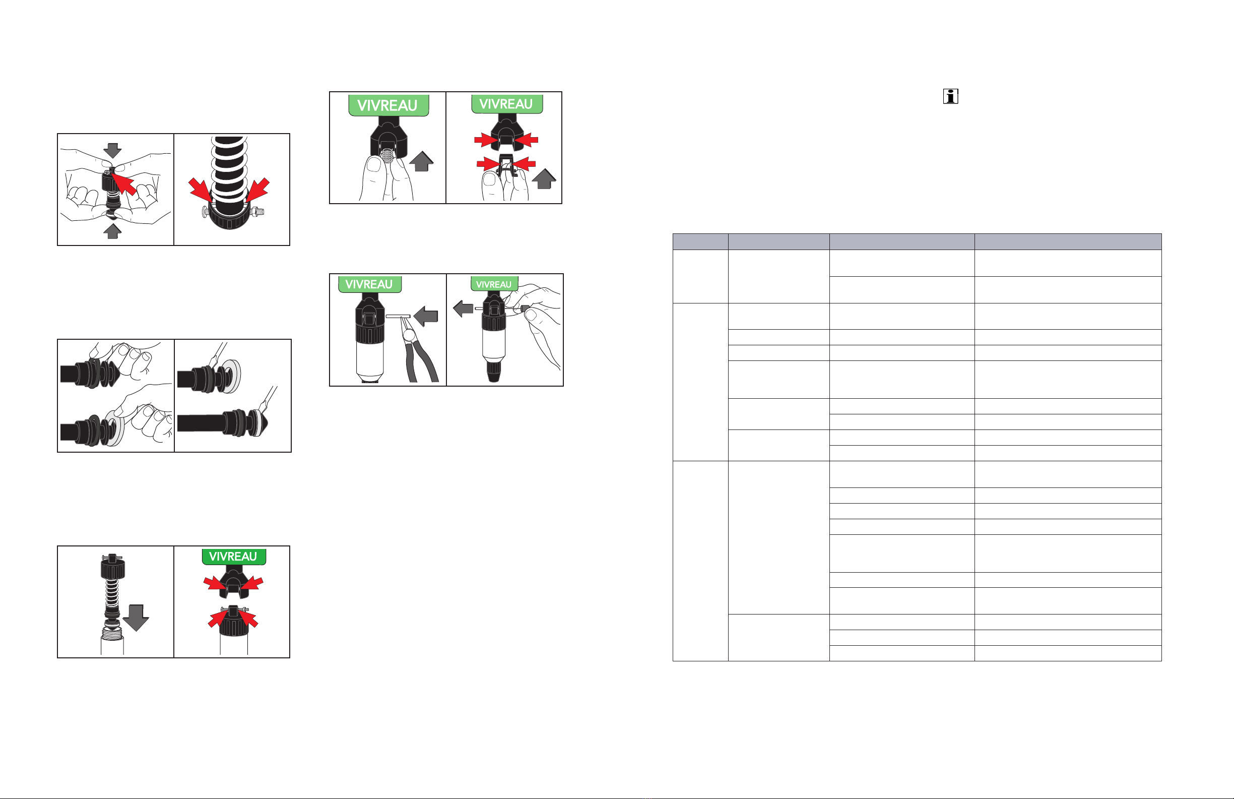
DISPENSER HANDLE ASSEMBLY CLEANING
Disassembly
Use Drift Pin to push the Roll Pin from the Dispenser
Handle
Remove the Roll Pin using pliers. Remove
Dispenser Handle.
Spring
Removing Roll Pin and Dispenser Handle
Secure with Screw and Nut to ensure it stays
together.
Rotate the top counter-clockwise. Remove
Assembly up from Dispenser Body.
Secure with Screw and Nut and
Rotate Top Counter-Clockwise
IMPORTANT ________________________
Wrap the metal Dispenser Body with plastic
film to prevent dirt from entering.
Press Dispenser Collar down rmly.
Remove Screw and release spring pressure gently.
Dispenser Collar and Screw Removal
REMOVING THE SEALS
With a at edged tool, pry the Seal from groove.
Remove Seal from groove.
Replace the Seal, if damaged.
Pry and Remove Seals from Groove
22 23
Reassemble the Dispenser
Press Dispenser Collar down rmly, reinsert screw
and release the spring pressure gently.
Alignment of the dimple and hole illustrated by the
position of the Screw.
Dimple and Hole Alignment
Gently feed into position and then work the
remainder around the piston into groove.
Use a at edged tool to ensure the Seal is located
correctly.
Position Seal with Flat Edged Tool
Reassemble Piston to Dispenser Body.
Screw the Cap onto the body. Ensure the Screw is
positioned properly to allow internal components
to align.
Reassemble Piston and Cap
Insert spring in Dispenser Handle.
Push in Plastic Insert and position with Screw.
Insert Spring and Position Plastic Insert
Position Dispenser Handle and align holes.
Drive Roll Pin back into position.
Dispenser Handle Roll, Pin In Position
Troubleshooting
The information provided in this section is intended
to assist in the identication and correction of any
irregularities and malfunctions which might occur
during operation.
IMPORTANT ________________________
Maintenance and repairs must be carried out by
properly qualied and trained personnel only.
Always switch OFF and unplug the equipment
before performing any service or repair
procedures.
CHILLER/CARBONATOR SYSTEM
Problem Possible problem Possible cause Action
Water
will not
dispense
Water frozen in Coil Ice bank too large
Faulty ice bank control
Replace
Poorly positioned/ faulty Ice
Sensor
Re-position/Replace Ice Sensor
No
sparkling
water
Water Pump or Motor
failure
Pump or Motor failure Replace Pump or Motor
Unit not switched ON Turned OFF Turn on to activate the carbonation system
Water Inlet Valve Faulty Replace Valve
Controller timed out Leak in system or too much water
dispensed in a short period
Check for leaks before re-setting Controller
– Achieved by interrupting the electrical
supply
CO2alarm sounds Low or no CO2supply Replace CO2supply
Faulty Pressure Switch Replace Switch
No dispense Fuse blown Check and replace
No electrical supply Check and resolve
Water
warm
Reduced ice weight or
long time to form ice
Faulty ice bank control Replace (taking care to not damage the
Sensor Bulb)
Fuse blown Check and replace
No electrical supply Check
Refrigeration system failure Replace base unit
Poor condenser cooling Check clearance around Cooler and Fan
Motor operation. Check Condenser and
clean if necessary
Insufcient water in Tank Top off water level
Supply voltage out of
specication
Check and resolve
Poor agitation of water
onto Cooling Coils
Motor failure Replace Motor/Pump
Motor Impellor failed Replace
Excessive algae growth in Tank Clean Tank and Coil outer surface
(continued on next page)

24 25
CHILLER/CARBONATOR SYSTEM (continued)
Problem Possible Problem Possible Cause Action
CO2
volume too
low
CO2pressure too low Regulator set incorrectly Reset CO2Regulator
Water warm Refer to ‘Water warm’ section Refer to Water warm section
Air in Carbonator System not purged during
connection
Vent Carbonator for ve (5) seconds
No CO2 Cylinder empty Reconnect to a new Cylinder
Regulator or Cylinder Valve
closed
Ensure both are open
Dispensing
Head
leaking
CO2pressure too high Regulator set incorrectly Reset CO2Regulator
Dispensing Head Seals blown
out of their position
Follow Dispensing Head maintenance
procedure to re-position Seals
Incorrect assembly
post cleaning process
Seals damaged or positioned
incorrectly
Re-perform Dispensing Head Assembly
and replace parts as required
Water
leaking
from the
green pipe
on front of
the unit
Check Valve failure Debris in Vented Check Valve
sited on the Carbonator Pump
Strip and clean as per instructions
contained in the Maintenance Section
Dispense
ow
incorrect
Incorrectly set Flow
Control
Not adjusted correctly Reset ow rate
IMPORTANT ________________________
Refrigeration System Failure Modes, Compressor Start Device, Over-Temperature Device in
Compressor, Open Circuit on Compressor Motor Windings, Refrigerant loss, Capillary Tube
blockage etc. are best diagnosed and repaired off-site in a shop environment.
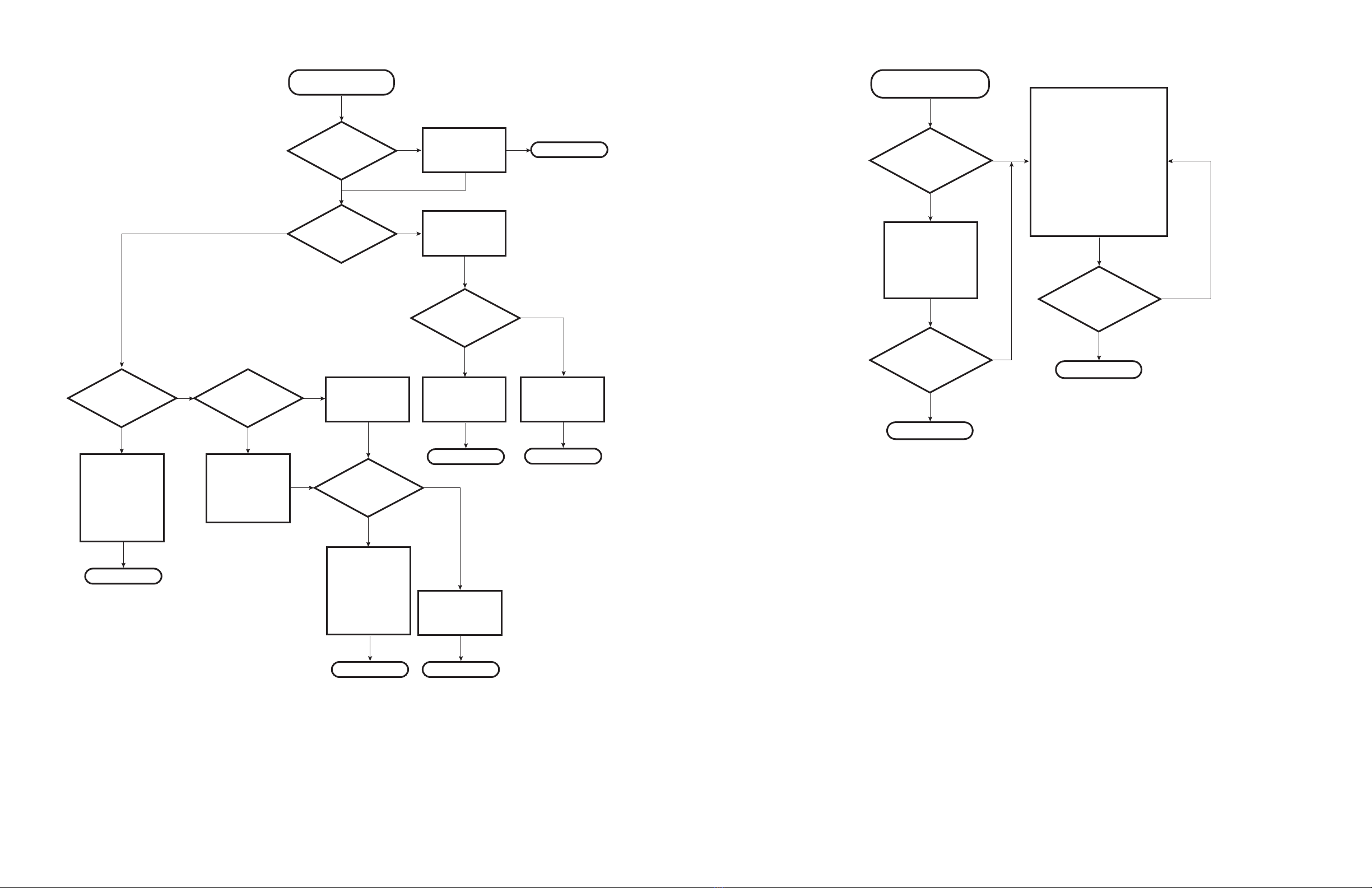
Yes
No
Is
Water Supply Valve
fully Open?
Change Filter
Open Valve and
Check for Proper
Operation
Still Water is Slower
Than Normal and/or
Carbonator is Running
Very Loud.
No Still Water
Thawing once should solve
the issue. If unit
continues to freeze up after
thawing, theThermostat
may need adjusting or
replacing.
Can 3 Liters
of Sparkling Water
be dispensed?
Still Water Coil is frozen. With
Power ON, open both
Dispensers and continue to
run Sparkling Water until Still
Water dispenses.This is the
fastest and only way to thaw
the Still Water.
Yes
Note
If only CO2
dispenses, there is a water
supply issue. Confirm that
Water Supply Valve to unit is
Open and working before
Dispatching ServiceTech.
Once water supply issue is
resolved, reset Carbonator.
Unplug the
Chiller/Carbonator and plug
back in to power the system
OFF and back ON again.
On Older Model,
check Water Block.
No
Note
Note
Problem resolved
Problem resolved
Problem resolved
Problem resolved

26 27
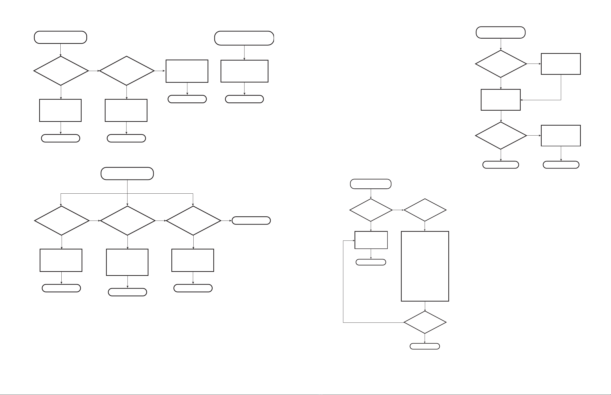
Water Leak
Confirm the leak is
coming from the
Vivreau System.
Repair leak.
Problem resolved
No Sparkling Water
Is CO2gas
dispensing
when Sparkling
Tap is open?
Yes
Yes
Confirm CO2
Cylinder Valve is
Open and Cylinder
is full. Confirm
pressure readings
on CO2Regulator.
Confirm CO2
Cylinder Valve is
Open and Cylinder
is full. Confirm
pressure readings
on CO2Regulator.
Make sure Power
Cord is plugged in
and the Outlet is
working.
No
Carbonator must
be reset to get the
Sparkling Water to
work again.
Unplug the
Chiller/Carbonator
and plug back in to
power the system
OFF and back ON
again.
Problem resolved
Problem resolved
Is Outlet Working? Resolve Power
Issue.
No Problem resolved
Service Light is ON
Does
Still Water
dispense from Still
Dispenser?
Yes Yes
Is Water
Supply Valve to
System Open and
working?
On Older Model,
check Water Block.
Remove and bypass
Water Block
No No
Is Still Water
slower than
normal?
Is water
restored?
Yes
No
No
Problem resolved
Carbonator must
be reset to get the
Sparkling Water to
work again.
Unplug the
Chiller/Carbonator
and plug back in to
power the system
OFF and back ON
again.
Sanitize and replace
Filter.
Yes
Problem resolved
Problem resolved
28 29
Water
Is Dispensing Warm
Is unit
plugged into a
working outlet? (Blue
Power Light
ON.)
Is Compressor
running?
Is Compressor
running?
Is water
being chilled?
No
No
No
No
No
Jump out
Terminals on
Thermostat
No Plug in unit
Replace
Thermostat
Yes
Once unit is
powered ON, it
may take up to 45
Minutes for the
water to dispense
cold and 4-6 Hours
to maintain a cold
Dispensing
Temperature.
Is the
Condenser Grille
clogged or
obstructed?
No
Yes
Clean the
Condenser Grille
with a Soft Brush
or Cloth and
remove any
obstructions to the
airflow.
Problem resolved
Problem resolved
Problem resolved
Once unit is
powered ON, it
may take up to 45
minutes for the
water to dispense
cold and 4-6 hours
to maintain a cold
Dispensing
Temperature.
Problem resolved
Yes
Yes
Yes
Yes
Confirm the Water
Supply Feeding
the unit is a Cold
Water Supply.
Yes
Is water
being
chilled?
Yes
Replace
Chiller
Problem resolved
Replace
Chiller
Problem resolved
No
Sparkling Water is Flat
Is CO2
Cylinder empty?
(CO2LED Illuminated)
or below 70 PSI on
Gauge.
Yes
No
No
No
Problem resolved
Flush the Sparkling Water:
1. Switch the Cleaning Mode
Switch OFF.
2.Touch and Hold the
Sparkling Button until only
Gas is dispensed.
3. Release the Button and
turn the Cleaning Mode
Switch back ON.
4. Let the unit cycle for 30
seconds and check the
Sparkling Water again.
Replace CO2
Cylinder and/or
make sure CO2
Cylinder Valve and
Secondary Shutoff
Valve (if equipped)
are open.
Yes
Is the
Sparkling
Water OK?
Yes
Problem resolved
Is the
Sparkling
Water OK?
Yes
30 31
Yes
No No
Replace CO2
Cylinder.
Is the CO2Cylinder
empty?
CO2LED is ON.
Yes
Is CO2
Cylinder Valve or
Secondary Shutoff
Valve closed?
Yes
No
Is the noise
constant and never
stops?
Yes
No No
Is the
noise after or
during dispensing
Sparkling Water
only?
Yes
Is the
noise during or
after dispensing either
Still or Sparkling
Water?
Open CO2Cylinder
and/or Secondary
Shutoff Valve.
Problem resolved
Check CO2Pressure
Switch and change
if needed.
Problem resolved
Problem resolved
Check for faulty
Agitator.
Problem resolved
Check Refrigeration
System.
Problem resolved
Problem resolved
Confirm Water
Supply Valve is fully
open before
checking for a
clogged Filter.
Problem resolved
Unit makes Loud Noise.
Drip Tray Light is ON.
Empty Internal or
External DripTray
Container.
Problem resolved
Is the Gasket
between the
Regulator andTank
in place?
Connect a new CO2
Cylinder. Monitor
CO2level over the
next 24-48 hours
Yes
No
Did new CO2
Cylinder hold
pressure?
Yes
No Find and correct
CO2leak.
Replace Gasket.
Problem resolved Problem resolved
CO2Leak
Problem resolved
Do both
Still and Sparkling
Water have a bad
taste?
Yes
No
No
Sanitize and replace
Filter.
Water Tastes Bad
Yes
Does only
Sparkling Water
have a bad
taste?
Yes
Is the issue
resolved?
Bad CO2Cylinder
Turn OFF the Power Switch
on the back of the unit and
dispense Sparkling Water
until only CO2is dispensed.
Turn OFF the CO2Cylinder
and dispense Sparkling Water
to release all CO2pressure.
Replace CO2Cylinder and
open Valve, dispense the
Sparkling Water for 5 seconds
to flush any residual CO2.
Turn the Power Switch back
ON and allow carbonator to
cycle.
Retest.
Problem resolved

32 33
Illustrated Parts List
GENERAL INFORMATION
HOW TO USE ILLUSTRATED PARTS LIST
Ordering Parts
Use this parts list to order parts for your Vivreau V3-
204 and V3-205 Dispensing System.
For your convenience, part numbers have been
included for all replaceable parts.
Illustrations
Item numbers on illustrations correspond with parts
listings on pages that accompany the drawings.
Notes are included on illustrations where needed.
Parts Listings
Parts listings identify serviceable parts with the
following categories:
Item - corresponds with numbers on illustrations
for part identication.
Description - species part name or description
of the item.
Quantity (Qty) - quantity required for assembly.
11
7
8 9 10
12
13
14
15
16
17a & 17b
18
19
21
20a & 20b
22
23
1
2
3
4
5
6
V3-204 Dispensing System Exploded View
Item
No. Part Number Description Qty
1 N/A Compressor Set THB1335YS LST 120V NA
2 1017463 Thermostat NA
3 1040297 Mini Bottler Cassette Fan NA
4 N/A Condenser NA
5 N/A Molded Handle NA
6 1017462 JG 3/8 x 5/16 Flow Regulator NA
7 1029135 AGIT-MOTOR-V3-204-US NA
8 1040270 Water Inlet Solenoid NA
9 N/A Level Probe NA
10 N/A Carbonator Bowl NA
11 1046015 Carb Motor NA
12 1040276 Vented Dual Check 3/8” mpt in 3/8” male are NA
13 1046076 Carb Pump NA
14 N/A Splash Cover – Controller NA
15 1040271 PCB Controller NA
16 N/A Inll Panel For Fascia NA
17a 1029146 Still Tap Lense US-BT-SP NA
17b 1029145 Sparkling Tap Lense US-BT-SP NA
18 N/A Water Tap NA
20b N/A Fascia Panel Blue Frost NA
21 N/A Drip Tray – Grill NA
22 1034117 Mini Bottler Drip Tray NA
23 N/A Adjustable Leg NA
NS 1046143 Co2 Reg Tank Kit NA
NS 1017470 Main Bottler LED-Buzzer Kit BT102-BT-SP NA
NS N/A Cleaning Mode Switch NA
NS 1040704 Pentair Stainless Steel 65psi PRV NA
NS 1023695 Tap Nozzles NA
V3-204 Dispensing System Parts List
34 35
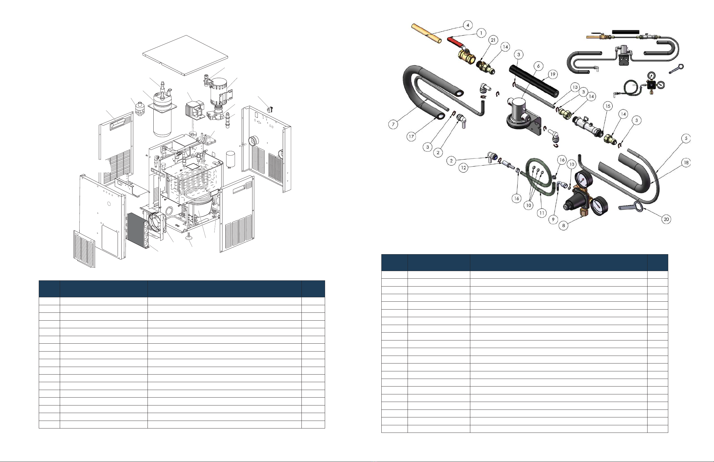
Vertical Cooler/Carbonator Under-Counter Range (120V 60Hz) Exploded View
5
3
16
1
2
4
15
96
7
10
13
11
14
8
12
Vertical Cooler/Carbonator Under-Counter Range (120V 60Hz) Parts List
Item
No. Part Number Description Qty.
1 N/A Compressor TL4G (120V; 50/60Hz) - Secop 1
2 1017463 Thermostat 1
3 1040297 Mini Bottler Cassette Fan 1
5 N/A Condenser 1
6 1029135 AGIT-MOTOR-V3-204-US 1
7 1040270 Water Inlet Solenoid 1
8 N/A Level Probe 1
9 N/A Carbonator Bowl 1
10 1046015 Carb Motor 1
11 1040276 Vented Dual Check 3/8” mpt in 3/8” male are 1
12 1046076 Carb Pump 1
13 1040271 PCB Controller 1
14 N/A Rocker Switch 273 235 1
15 1017465 ViTap Dual Solenoid Assembly 1
16 1030554 PCB Board NA VT-SP Vitap 1
17 1040704 Pentair Stainless Steel 65psi PRV 1
18 N/A Foot M8 Adjust Lvl RS750-777 1
Item
No. Part Number Description Qty.
1 Shut off valve Supplied By Client 1
2 1019479 Gray Acetal Plug In Elbow 3/8 Stem - 3/8 Tube 4
3 1046036 Locking Clip, 3/8 9
4 Water supply Supplied By Client 1
5 1046021 LLDPE Tubing 3/8 OD, Black (500 ft. Roll) 1
6 1025659 VH-3 Filter Head 1
7 1025665 .380 Whiteline Braided Bev Tube (300’ roll) 1
81040294 Reg Pri WM 160 W/6’ Hose Attchd 1
91040289 Swivel ELL 1/4 Barb x 1/4 FFL 1
10 1040281 Nylon Washer White 1/4 4
11 1040283 .265 Whiteline Braided Bev Tube (500’ roll) 1
12 1024849 Tube To Hose Stem 3/8 Stem - 1/4 Hose 1
13 1046021 LLDPE Tubing 3/8 OD, Black (500 ft. Roll) 1
14 1019480 Gray Acetal Female Connector 3/8 X 1/2 BSPP (Cone End) 3
15 1025656 Dual Check Valve With Shutoff 1
16 1040284 12.3 Stepless Clamp (100 pack) 2
17 1045998 Insulation Pipe 3/8” ID x 3/8” x6 1
18 1046002 6’ Pipe Insulation 1
19 1046002 6’ Pipe Insulation 1
20 1025664 CO2 Regulator Wrench 1
21 1025667 Hose Nipple 1/2 Mpt x 1/2 Mpt Hex 1
204 Installation Parts
No Water-block

36 37
Wiring Diagrams Contact Info
Phone Number:
+1 877 999 1044
Email:
InfoUSA@vivreau.com
InfoCanada@vivreau.com
Or visit vivreauwater.com
LNE
INDICATOR PANEL – NOT VISIBLE
COLOR KEY:
WHITE = WHT
BLACK = BLK
BLUE = BLU
BROWN = BRN
RED = RED
ORANGE = ORG
GREEN = GRN
GREEN/YELLOW = G/Y
LOW
HIGH
SIGNAL
CONTROLLER
314015000-100
INPUT
115V L2
L1
CONDENSER
FAN
WIRING SCHEMATIC
WATER
BOOST
PUMP
SOLENOID
CO2
SWITCH
PROBE
EARTH
MAINS INPUT
TERMINAL
BLOCK
CHASSIS
EARTH BASEPLATE
ICEBANK
THERMOSTAT COMPRESSOR AGITATOR
WHT
WHT
WHT
WHT
WHT
WHT
WHT
WHT
WHT
BLK
BLK
BLK
BLK
BLK
BLK
BLK
BLK
BRN BRN
BLU
G/Y
G/Y
G/Y G/Y
G/Y
G/Y
CARBONATOR
BOWL
GRN
RED
ORG
LABEL: 06-0-388312-1 PLUMBING SCHEMATIC
WATER
BOOST
PUMP
SOLENOID
VALVE
DOUBLE
CHECK
VALVE
CO2
CHECK
VALVE
FLOW
CONTROL
WATER COIL
WATER COIL
CARBON DIOXIDE (CO2)
CARBONATOR
BOWL
PRV
TAP
TAP
WATER
IN
COOLER
Vivreau V3-204 and V3-205 Wiring Diagram and Plumbing Schematic
Other manuals for V3-204
2
This manual suits for next models
1
Table of contents
Other Vivreau Dispenser manuals


