Nordson EFD Ultimus I User manual

Ultimus I-III Dispenser Pressure Readout,
VacuumReadout, and Dispense Timer Validation
Instructions
Introduction
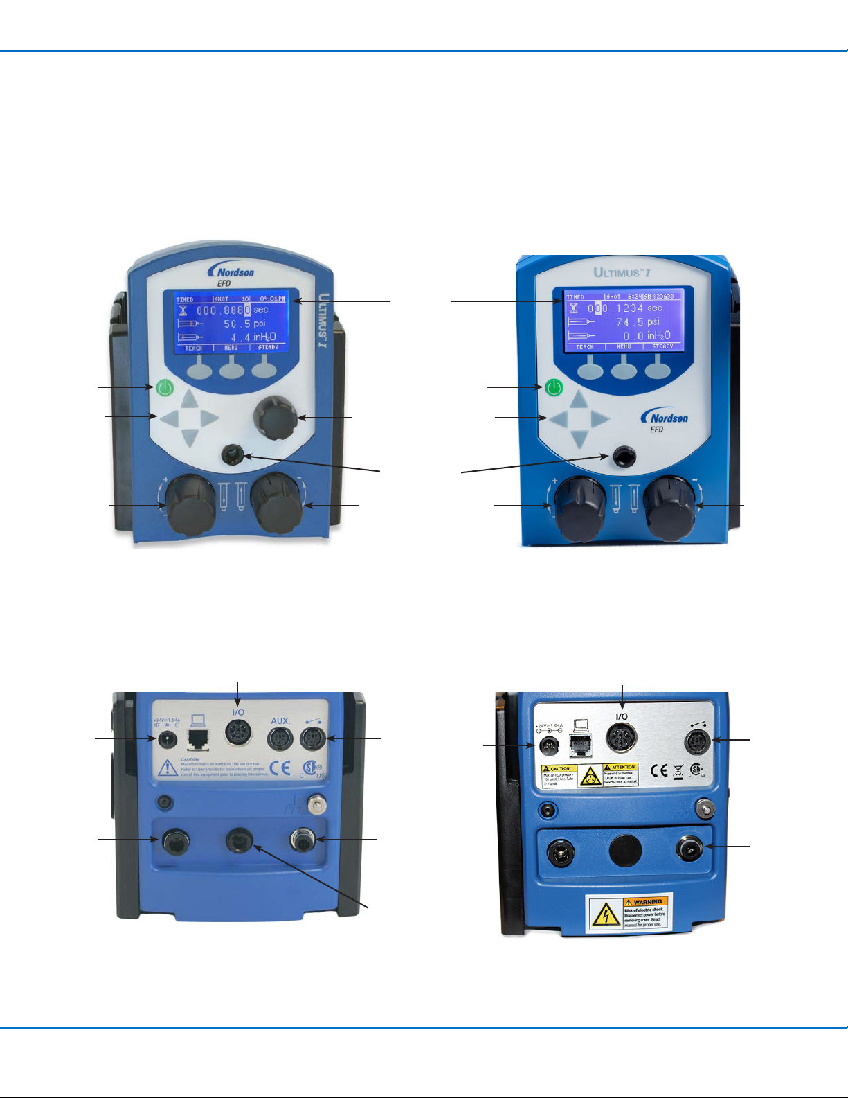
These instructions provide the pressure, vacuum, and dispense timer validation procedures for the following dispensers:
• Ultimus™I: P/N 7017041 • Ultimus II: P/N 7002003 • Ultimus III P/N 7017068 (legacy)
Specification List
Model Pressure Accuracy Vacuum Accuracy Timer Accuracy
Ultimus I ±2.0 psi, 0–100 psi ±2.0 inH2O, 0–6 inH2O ±0.05%
Ultimus II ±0.3 psi, 0–15 psi ±2.0 inH2O, 0–6 inH2O ±0.05%
Ultimus III ±0.3 psi, 0–5 psi ±2.0 inH2O, 0–6 inH2O ±0.05%
Required Tools and Supplies
The following equipment is required for the performance of these procedures.
# Description Minimum Accuracy Requirement Suggested
Equipment Purpose
1* Precision pressure
and vacuum test
gauge
±0.05 psi at 0–100 psi
±0.33" H2O
Fluke, model 700G06
pressure and vacuum
test gauge
Reference standard for 100/15 psi
pressure and 6" H2O vacuum
2 0–100 psi test gauge,
±0.25% full scale
accuracy
±0.25 psi WIKA®, model 312.20 6,
P/N 9746892
Reference standard for validating the
Ultimus I pressure readout
3 0–15 psi test gauge,
±0.25% full scale
accuracy
±0.05 psi WIKA®, model 312.20 6,
P/N 9746867
Reference standard for validating the
Ultimus II and III pressure readouts
4 Slack tube
manometer, 18-0-18"
±0.33" H2O Dwyer Instruments,
model 1211-36
Reference standard for validating the
Ultimus I, II, and III vacuum readouts
5 Function generator,
triggered 10 s pulse,
±1 ppm accuracy
±20 ppm for a 10 s triggered pulse;
5–24V for ON,
0V for OFF
Load: 1,200 ohms
Tektronix®, AFG 3021B Reference standard for validating the
Ultimus I, II, and III dispense timer
*Item 1 is the preferred equipment and can be used in place of items 2-4. When item 1 is used, only item 5 is also required.
Optional Accessories
The following recommended Nordson EFD accessories are available to support the performance validation and field validation of the
vacuum display.
Accessory Description Nordson EFD
Part Number Purpose
Input / output (I/O) cable,
Ultimus I, II, III
8-pin DIN cable, color coded
leads, stripped and tinned lead
ends, 1.9 m (6 ft)
7017143 Connection to Ultimus I, II, or III from the function
generator for validation of the dispense timer
Vacuum calibration kit,
Ultimus I, II, III
Nordson EFD vacuum
calibration software, USB to
RS-232 converter, RS-232 to
modular plug cable
7028817 Adjustment of the Ultimus I, II, or III vacuum
readout validation; kit provides hardware and
software for site-specific validation of the digital
vacuum readout

Ultimus I-III Dispenser Pressure Readout, Vacuum Readout, and Dispense Timer Validation
2www.nordsonefd.com [email protected] +1-401-431-7000 Sales and service of Nordson EFD dispensing systems are available worldwide.
Pressure Readout Validation
The Ultimus I–III digital pressure readings are validated against a pressure standard with a known minimum accuracy. The pressure
standard must be at least ±0.25 psi for Ultimus I and ±0.05 psi for Ultimus II and III. Refer to the equipment list for suitable test
gauges. The digital pressure readout accuracy specification of the Ultimus I–III is ±2.0% of full scale range. Each of the five pressure
validation points are applied and confirmed by the calibrated pressure standard. Maximum readout deviation, as observed on the
Ultimus digital pressure display, at any of the five points, is listed in the table below.
Pressure Readout Performance Validation Points
The following table provides the pressure validation points and maximum deviation for Ultimus I–III digital pressure readings.
Product Model Verification Points (psi) Maximum Deviation
Ultimus I (100 psi) 20, 40, 60, 80, 95 ±2.0 psi
Ultimus II (15 psi) 2, 6, 9, 12, 15 ±0.3 psi
Ultimus III (5 psi) 1, 2, 3, 4, 5 ±0.3 psi
Validation Procedure
Refer to the Ultimus Operating Manual and Quick Start Guide for connection and setup instructions.
1. Connect a foot pedal to the foot pedal port on the rear panel.
2. Set the air pressure to the minimum setting by turning the pressure regulator knob fully counterclockwise.
3. Set the vacuum to the minimum setting by turning the vacuum regulator knob fully counterclockwise.
4. Verify that the rear panel exhaust port is open.
5. Connect the 100 psi or 15 psi test gauge to the front or rear panel air output port.
6. Connect the dispenser air input to a 100 psi regulated air supply.
7. Plug the power supply DC connector into the rear panel power input port.
8. Plug the power supply into an AC power source.
9. Press the power switch to power ON the Ultimus dispenser.
10. Select STEADY mode using the Ultimus screen and/or menu controls.
11. Select “psi” for pressure units using the Ultimus menu controls.
12. Press and hold the foot pedal.
13. Adjust the pressure regulator to the first verification point specified in the “Pressure Readout Performance Validation
Points” on page 2 as monitored on the test gauge.
NOTE: Adjust to verification points in a clockwise direction, never counterclockwise.
14. Ensure that the test gauge reading is exact by releasing and pressing the foot pedal, adjusting the pressure regulator
if necessary, to attain a repeatable pressure.
15. Record the pressure reading from the Ultimus digital display.
16. Release the foot pedal.

3www.nordsonefd.com [email protected] +1-401-431-7000 Sales and service of Nordson EFD dispensing systems are available worldwide.
Ultimus I-III Dispenser Pressure Readout, Vacuum Readout, and Dispense Timer Validation
17. Repeat steps 12 through 16 for all verification points.
18. Evaluate the five pressure digital display readings against the maximum deviation criteria shown in the “Pressure
Readout Performance Validation Points” on page 2.
Validation Procedure (continued)
Date / time
control knob
Air
input
port
Power
switch
Legacy Ultimus I, II, and III dispenser
front panel components
Pressure
regulator
knob
Exhaust
port
I/O port
Power
input
port
Menu
navigation
arrows
Digital
display
Ultimus I and II dispenser
front panel components
I/O port
Foot
pedal
port
Back panel air
output port
Foot
pedal
port
Power
input
port
Vacuum
regulator
knob
Vacuum
regulator
knob
Pressure
regulator
knob
Power
switch
Menu
navigation
arrows
Front panel air
output port
Air
input
port
Legacy Ultimus I, II, and III dispenser
back panel components
Ultimus I and II dispenser
back panel components

Ultimus I-III Dispenser Pressure Readout, Vacuum Readout, and Dispense Timer Validation
4www.nordsonefd.com [email protected] +1-401-431-7000 Sales and service of Nordson EFD dispensing systems are available worldwide.
Vacuum Readout Validation
The Ultimus I–III digital vacuum readings are validated against a calibrated vacuum standard. Accuracy of the standard must be at
least ±0.33 inH2O. Refer to the equipment list for a suitable vacuum test instrument. The digital vacuum readout accuracy specification
of the Ultimus I–III is ±2.0 inH2O. Each of the vacuum verification points are applied and confirmed by the calibrated vacuum standard.
The Ultimus I–III exhaust port must be unobstructed for this assessment. Maximum readout deviation, as observed on the Ultimus
digital vacuum display, at any of the verification points is ±2.0 inH2O.
Vacuum Readout Performance Validation Points
The following table provides the vacuum validation points and maximum deviation for Ultimus I–III digital vacuum readings.
Product Model Verification Points (inH2O) Maximum Deviation
Ultimus I, II, or III 2, 6 ±2.0 inH2O
Validation Procedure
Refer to the Ultimus Operating Manual and Quick Start Guide for connection and setup instructions.
NOTE: The vacuum readout can be field-calibrated using the Ultimus I, II, III Vacuum Calibration Kit (P/N 7028817), available from
Nordson EFD. A description and contents of the kit is shown under “Optional Accessories” on page 1.
1. Set the air pressure to the minimum setting by turning the pressure regulator knob fully counterclockwise and
pushing the knob to lock the setting.
2. Set the vacuum to the minimum setting by turning the vacuum regulator knob fully counterclockwise.
3. Connect the vacuum test instrument to the front or rear panel air output port.
4. Verify that the rear panel exhaust port is open.
5. Connect the dispenser air input to a 100 psi regulated air supply.
6. Plug the power supply DC connector into the rear panel power input port.
7. Plug the power supply into an AC power source.
8. Press the power switch to power ON the Ultimus dispenser.
9. Select “inH2O” for vacuum units using the Ultimus menu controls.
10. Adjust the vacuum regulator to the first verification point specified in the “Vacuum Readout Performance Validation
Points” on page 4 as monitored on the vacuum test instrument.
11. Ensure that the reading on the vacuum test instrument is exact, adjusting if required.
12. Record the vacuum reading from the Ultimus digital display.
13. Repeat steps 10 through 12 for all verification points.
14. Evaluate the vacuum digital display readings against the maximum deviation criteria shown in the “Vacuum Readout
Performance Validation Points” on page 4.

5www.nordsonefd.com [email protected] +1-401-431-7000 Sales and service of Nordson EFD dispensing systems are available worldwide.
Ultimus I-III Dispenser Pressure Readout, Vacuum Readout, and Dispense Timer Validation
Dispense Timer Validation
The accuracy specification of the Ultimus I–III dispense timer is ±0.05% of the selected time setting. Validation of the Ultimus I–III
dispense timer is performed by comparing an external time pulse that is known to be accurate to the internal timing reference of the
Ultimus I–III. This timing reference establishes the dispense timer accuracy of the Ultimus I–III. The external time pulse is wired to the
“Voltage Initiate” circuit on pins 1 and 2 of the I/O connector and measured by the Ultimus I–III TEACH feature.
The measured TEACH result shown on the Ultimus I–III display will be:
External Pulse Time minus 0.0060 s (seconds).
Ultimus I–III dispensers add 0.0060 s to all dispense times to compensate for solenoid lag.
Tektronix AFG 3021B Function Generator Setup
The Tektronix AFG 3021B function generator, or an other verified pulse generator, can be used. Setup for an AFG 3021B is provided
below. A single external time pulse of 10.0 s is specified to provide a high-resolution measurement.
Function: Pulse
Run Mode: Burst, N-Cycle = 1
Frequency/Period: Period, Period = 12.00000000 s
Duty/Width: Width, Width = 10.000 s
Amplitude/High: High, High = 10.00 v
Offset/Low: Low, Low = 0 mv
Output Menu: Load = High Z, Noise Add = Off
Output: 50 ohm connector
Channel Button: ON to Enable Trigger
Trigger: Manual, Panel Button
Validation Procedure
Refer to the Operating Manual for instructions on connecting to the I/O connector and for using the TEACH mode.
1. Configure the pulse generator as described above.
2. Connect the pulse generator output to pins 1 and 2 of the I/O connector.
3. Plug the power supply DC connector into the rear panel power input port.
4. Plug the power supply into an AC power source.
5. Press the power switch to power ON the Ultimus dispenser.
6. Select the TEACH mode.
7. The time display should be zero. If not, press the CLEAR button.
8. Initiate the external 10 s time pulse:
• The Ultimus I–III time display will ideally read 9.9940 s at the conclusion of the
10.0 s initiate pulse.
• For a 10 s initiate pulse, the acceptable readout range is
9.9890 to 9.9990 s [(10.0–0.006) ±0.005 s].
For Nordson EFD sales and service in over
40 countries, contact Nordson EFD or go to
www.nordsonefd.com.
800-556-3484; +1-401-431-7000
Tektronix is a registered trademark of Tektronix, Inc.
WIKA is a registered trademark of WIKA Instrument Corporation.
©2020 Nordson Corporation 7028813 v062420
This manual suits for next models
5
Table of contents
Other Nordson EFD Dispenser manuals

Nordson EFD
Nordson EFD UltimusPlus I User manual

Nordson EFD
Nordson EFD Performus I User manual

Nordson EFD
Nordson EFD E2 User manual

Nordson EFD
Nordson EFD 2K Pneumatic Dispense Gun User manual

Nordson EFD
Nordson EFD HP Series User manual

Nordson EFD
Nordson EFD PROPlus Series User manual

Nordson EFD
Nordson EFD Ultimus I User manual

Nordson EFD
Nordson EFD Ultimus IV Series User manual