VOLKTEK IRF-633 User manual

IRF-633
RS-232/422/485 to 10/100Base-TX
Device Server/Managed Media
Converter
User Manual
(Dec 2007)

IRF-633 RS-232/422/485 TO 100BASE-TX DEVICE SERVER
COPYRIGHT
All rights reserved. No part of this publication may be reproduced, stored in a retrieval system,
or transmitted in any form or by any means, whether electronic, mechanical, photo copying,
recording or otherwise, without the prior written permission of the publisher.
FCC WARNING
This equipment has been tested and found to comply with the limits for a class A device,
pursuant to part 15 of FCC rules. These limits are designed to provide reasonable protection
against harmful interference in a commercial installation. This equipment generates, uses and
can radiate radio frequency energy and, if not installed and used in accordance with the
instructions, may cause harmful interference to radio communication. Operation of this
equipment in a residential area is likely to cause harmful interference, in which case, the user
will be required to correct the interference at the user’s own expense.
CE
This is a Class A product. In a domestic environment, this product may cause radio interference
in which case the user may be required to take adequate measures.
Take special note to read and understand all the content in the warning boxes:
Warning
i

RS-232/422/485 TO 100BASE-TX DEVICE SERVER
ii
TABLE OF CONTENTS
1ABOUT THIS GUIDE..........................................................................1
1.1 Welcome............................................................................................................1
1.2 Purpose .............................................................................................................1
1.3 Terms/Usage .....................................................................................................1
1.4 Features.............................................................................................................1
1.5 Specifications ...................................................................................................2
1.6 Package Contents.............................................................................................3
2HARDWARE DESCRIPTION .............................................................4
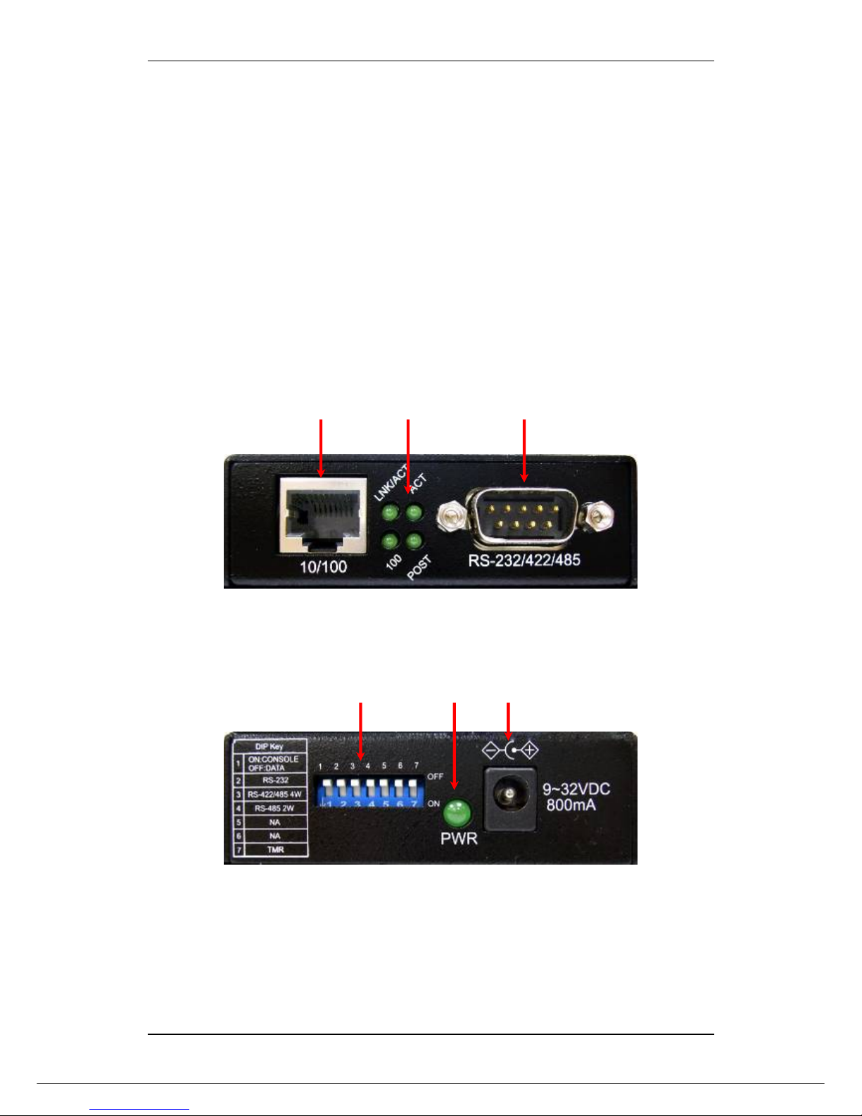
2.1 Product Overview .............................................................................................4
2.2 Product Illustrations.........................................................................................4
3INSTALLATION..................................................................................5
3.1 Location.............................................................................................................5
3.2 Wall Mount Installation.....................................................................................5
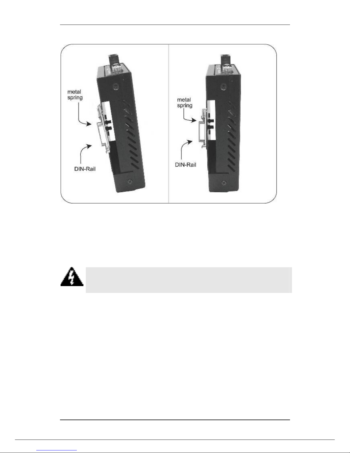
3.3 Din Rail Mount Installation...............................................................................5
3.4 Powering On Unit..............................................................................................6
3.5 DB9 Male Connector Pin Assignments...........................................................7
3.6 Serial Connection .............................................................................................7
4LED INDICATORS .............................................................................9
5USER INTERFACE STARTUP.........................................................10
5.1 Console Port Access...................................................................................... 10
5.2 Telnet Access..................................................................................................12
5.3 Web Access.....................................................................................................13
6CONFIGURATION MANAGEMENT.................................................14
6.1 Menu-driven User Interface............................................................................14
6.1.1 System Information Menu...............................................................................................14
6.1.2 DHCP Configuration Menu..............................................................................................15
6.1.3 Serial Port Config Menu ..................................................................................................16
6.1.4 RS-232/422/485 UART Menu ...........................................................................................20
6.1.5 Connection Status ...........................................................................................................20
6.1.6 TFTP Firmware Upgrade .................................................................................................21
6.1.7 SNMP Configuration........................................................................................................21
6.1.8 System Restart Menu ......................................................................................................23
6.2 Command Line Interface ................................................................................24
6.3 Web Graphic User Interface........................................................................... 25
6.3.1 System Information .........................................................................................................25
6.3.2 Master Information ..........................................................................................................25
6.3.3 Serial Port Configuration ................................................................................................25

RS-232/422/485 TO 100BASE-TX DEVICE SERVER
iii
6.3.4 Serial Connect Status......................................................................................................30
6.3.5 User Configuration ..........................................................................................................31
6.3.6 Firmware Download ........................................................................................................31
6.3.7 Configuration File Backup and Restore ........................................................................32
6.3.8 SNMP Community Configuration ...................................................................................32
6.3.9 IP Trap...............................................................................................................................32
6.3.10 System Restart...............................................................................................................33
7APPENDIX: RS-232 CABLE CONNECTION DIAGRAM.................34
8CONTACT INFORMATION ..............................................................45

IRF-633 RS-232/422/485 TO 100BASE-TX DEVICE SERVER
1
1 About This Guide
1.1 Welcome
Thank you for selecting the IRF-633 RS-232/422/485 to 10/100Base-TX Device Server
/ Managed Media Converter. This unit is designed to provide an RS-232/422/485
connection over twisted-pair cable where the connected devices have RS-232/422/485
interfaces. Enabling serial devices such as CNCs and PLCs to instantly connect to an
existing Ethernet/ Fast Ethernet network, the Serial-to-Ethernet Device Server /
Managed Media Converter represents a robust solution for devices controllers for MIS
personnel. This product can either be used as Device Server or Managed Media
Converter.
1.2 Purpose
This guide discusses how to install and configure your IRF-633 Device Server/
Managed Media Converter.
1.3 Terms/Usage
In this guide, the term “Device Server/Managed Media Converter” (first letter upper
case) refers to your IRF-633, and “device server / managed media converter” (first
letter lower case) refers to other device servers / managed media converter.
1.4 Features
•IRF-633 Device Server & Managed Media Converter Mode option
•Complies with EIA/TIA and IEEE standards
•Supports 4 wires full duplex asynchronous serial data transmission (RS-422/485)
•Supports 2 wires half-duplex asynchronous serial data transmission (RS-485)
•Supports serial port asynchronous data rates up to 115.2 Kbps
•Extended distances up to 1.2 km (24 AWG) using RS-422/485
•Auto-detecting 10/100 Mbps Ethernet interface
•Terminator feature improves signal quality and distance
•LEDs for ‘at-a-glance’ device status
•Wall mount or Din-Rail mountable installation
•Power range 9~32V DC
•FCC Class A & CE approved

IRF-633 RS-232/422/485 TO 100BASE-TX DEVICE SERVER
2
1.5 Specifications
Standards: IEEE 802.3 (10BASE-T Ethernet);
IEEE 802.3u (100BASE-TX/ Fast Ethernet); EIA/TIA RS-
232/422/485; EIA/TIA-5744
Ports: 1x UTP 100/120ohm; RJ-45 type
1x 9-pin serial connector; D-sub, Male
Max. Distance: UTP: 100 meters (Cat 3/4/5.)
Serial: 15 meters (RS-232)
1,200 meters (RS-422, RS-485)
Data Rates: UTP: 10 or 100 Mbps
Serial: 115.2 kbps (asynchronous)
Signals: RS-232: TxD, RxD, CTS, RTS, DTR, DSR, RI, DCD, GND RS-422:
TxD+/-, RxD+/-, GND RS-485: Data+, Data-, GND
Configuration: Bits Per Second: 38400
Parity: None
Data bits: 8
Stop bits: 1
Flow Control: None
(The console connection is only available once the DIP switch 1 is
ON)
Switches: DIP 1: Enables / disables console / data communication mode
DIP 2: Enables / disables RS-232
DIP 3: Enables / disables RS- 422/485 (4-wire)
DIP 4: Enables / disables RS-485 (2-wire)
DIP 5: N/A
DIP 6: N/A
DIP 7: Enables / disables termination (TMR)
Power: External power adapter; 9~32V DC @800mA
Frequency: 47Hz to 63Hz
Environment: Temperature: Operating: 0°C to 50°C
Relative Humidity: 10% to 80%, non-condensing
Storage: -20°C to 80°C
Relative Humidity: 5% to 90%, non-condensing
Emissions: FCC Part 15 of Class A & CE approved
Dimensions: 109.2 x 90 x 30mm (L x W x H)
Weight: 280 grams

IRF-633 RS-232/422/485 TO 100BASE-TX DEVICE SERVER
3
1.6 Package Contents
The package should include the following:
•One IRF-633 Device Server / Managed Media Converter
•One power adapter (please check connector type and input power specification)
•Four self-adhesive pads
•DIN Rail Kit
•Screws for wall-mount installation
•Quick Installation Guide
•User’s Manual CD
•Serial IP Redirector software CD

IRF-633 RS-232/422/485 TO 100BASE-TX DEVICE SERVER
2 Hardware Description
2.1 Product Overview
The IRF-633 features complete Ethernet and TCP/IP network support that allows
devices in industry with RS-232/422/485 connectors such as milling machines,
measurement instruments, and robots to connect to LAN based automation. Other
devices typically found on campus networks such as card readers, code readers, lab
equipment, medical equipment, and other similar serial devices can now instantly
migrate to a TCP/IP network. Additionally, by deploying the device server mode, enable
users to monitor and manage up to 256 serial devices from single PC with the help of
Serial IP Redirector software for Device Server mode.
2.2 Product Illustrations
Front Panel
RS-232/422/485,
DB9 Male
RJ-45 LEDs
Rear Panel
DIP Switches Power LED Power Connector
4

IRF-633 RS-232/422/485 TO 100BASE-TX DEVICE SERVER
5
3 Installation
To install your IRF-633, please see the following procedures:
•Location
•Din Rail Mounting
•Desktop Installation
•Powering On Unit
•Connecting Copper Cables
•DB9 Male Connector Pin Assignment
•Serial Connection
•Ethernet Connection
3.1 Location
The location selected for installing the IRF-633 may greatly affect its performance.
When selecting a site, we recommend considering the following rules:
1. Install the IRF-633 in a fairly cool and dry place. See Technical Specifications for
the acceptable temperature and humidity operating ranges.
2. Install the IRF-633 in a location free from strong electromagnetic field generators
(such as motors), vibration, dust, and direct exposure to sunlight.
3. Leave at least 5cm of space at the front and rear of the unit for ventilation.
4. Affix the provided rubber pads to the bottom of the IRF-633 for grip, and to protect
the case from scratching.
3.2 Wall Mount Installation
The Device Server/Managed Media Converter can also be installed by wall mounting.
The backside casing provides space for two screws each side. Identify the exact
location at wall by placing the IRF-633 and marking the screw positions. Use the screw
(include in the package) and snug them well to fix the IRF-633.
3.3 Din Rail Mount Installation
The aluminum DIN Rail attachment plate should already be affixed to the back panel of
the IRF-633. If you need to attach the DIN Rail plate, assure that the stiff metal spring
is situated towards the top. Attaching the IRF-633 to the DIN rail is easy, just align, and
attach the top rail, then press down and snap forward the IRF-633 to snap in the
bottom rail, as shown in the figures below.

IRF-633 RS-232/422/485 TO 100BASE-TX DEVICE SERVER
Use following steps set up the IRF-633:
•The surface must support at least 500 gm for the IRF-633.
•The power outlet should be within 1.82 meters (6 feet) of the IRF-633.
•Visually inspect the power adapter and make sure that it is properly connected.
Make sure that there is proper heat dissipation from and adequate ventilation around
the IRF-633. Do not place heavy objects on the product.
Warning Please exercise caution when using power tools. Also, install this
unit away from damp or wet locations, or in close proximity to very hot
surfaces. These types of environments can have a detrimental effect on the
unit and cables.
3.4 Powering On Unit
The IRF-633 uses external power supply 9~32V DC @ 0.8A 50~60 Hz.
1. Insert the power cable plug directly into the receptacle located at the back of the
device.
2. Plug the power adapter into an available socket.
3. Check the rear-panel LEDs as the device is powered on to verify that the Power
LED is lit. If not, check that the power cable is correctly and securely plugged in.
6
NOTE: The RJ-45 port accepts both ‘straight-through’ and ‘cross-over’ Ethernet cables
without the need to re-configure the port.

IRF-633 RS-232/422/485 TO 100BASE-TX DEVICE SERVER
3.5 DB9 Male Connector Pin Assignments
PIN RS-232
(Full-duplex)
RS-422/485
4-wire
(Full-duplex)
RS-485
2-wire
(Half-duplex)
1 DCD
2 RX RX- **DATA B(-)
3 TX TX-
4 DTR
5 GND GND GND
6 DSR
7 RTS RX+ **DATA A(+)
8 CTS TX+
9 RI
NOTE: Bi-directional RS-485 BUS line.
For RS-232 cable connection, use cross-over cable when connecting to a DTE device,
and straight-through cable for connecting to a DCE device. See Appendix for
illustration.
3.6 Serial Connection
This IRF-633 features DIP switches on the rear panel that sets the unit to the correct
type of cable configuration to support connection with a RS-232 / 422 / 485 device.
Definition of DIP Switches
No Dip description Default
1 ON: Console / OFF: Data OFF
2 RS-232 ON
3 RS-422 / 485 (4W) OFF
4 RS-485 (2W) OFF
5 NA OFF
6 NA OFF
7 TMR (Terminator) OFF
For setting the control function of the serial port, see the table below:
DIP 1 Serial Connection
ON RS-232 Console
OFF Data Communication
NOTE:
1. If using console mode turn the DIP Switch 1 to ON position. For data
communication from the serial device keep the DIP switch 1 to OFF position. In
case of ON position data communication will be blocked and at OFF position
console port access blocked.
2. In RS-232 Condole mode (DIP Switch 1 = ON), all other DIP Switch settings are
ignored. In Data Communication mode (DIP Switch 1 = OFF), properly set other
DIP Switches for serial interface modes.
7
3. For some RS-422/485 devices, which may not be designed to provide DB-9
connection, please check the pin definition to connect the devices.

IRF-633 RS-232/422/485 TO 100BASE-TX DEVICE SERVER
8
4. For the first time installation, you have to use console mode to setup the IP and
TCP port configuration with RS-232 cable. Always use Cross Over cable, if using
Straight Through, you must use “Null Modem” to use Telnet option.

IRF-633 RS-232/422/485 TO 100BASE-TX DEVICE SERVER
9
4 LED Indicators
This device has LED indicators located at the front of the device. The LEDs have been
designed to give easy at-a-glance network status, and provides ‘real-time’ connectivity
information. Please see below for an interpretation of their functions:
LED Indicators
LED Condition Status
On (Green) Unit is receiving power
PWR Off Power off or failure
On (Green) Illuminated when RJ-45 connector attached and
link signals received
LNK / ACT
(RJ-45) Flashing (Green) Data traffic passing through RJ-45 port
Off No link established
100 On (Green) RJ-45 port in 100Base mode
Off Port is operating at full duplex
On (Green) Receiving data packets
ACT Flashing RS-232/422/485 data packets being transmitted
or received
Off No data packets received
POST On (Green) Indicates normal operation

IRF-633 RS-232/422/485 TO 100BASE-TX DEVICE SERVER
5 User Interface Startup
There are two separate methods for configuring this IRF-633 for use. In the first section
of this chapter, the Command line Interface (CLI) or Menu-driven interface via the
Console Port to set the device IP and TCP configuration to monitor/managed the
attached serial device via Serial IP Redirector software. The second section will
describe CLI or Menu-driven via Telnet configuration. Firstly, make the connection
below:
DIP Switch 1 set to ‘ON’ position
5.1 Console Port Access
The IRF-633 is accessible via a terminal emulator attached to the RS-232 console port.
Please follow the step below.
1. Attaching the serial cable to COM port of computer and serial port of device server.
2. Select Hyper Terminal from (start menu Æprograms ÆAccessories Æ
communication) a window will appear, assign the connection name. Then select the
correct available COM port (COM1 or COM2). After this enter the port settings as
below.
Bits per seconds: 38400
Data bits: 8
Parity: None
Stop bits: 1
Flow Control: None
3. Once connection is established, you will see a log in screen.
10
Device
Serve
r
Female
Female
Compute
r
RS-232 Cable

IRF-633 RS-232/422/485 TO 100BASE-TX DEVICE SERVER
Press ENTER and on the following screen, type the default username admin, leave the
password field blank since there is no default value and press ENTER to proceed.
4. Select either CLI User Interface or Menu-driven Interface option by using the
associated number key or using the TAB key and pressing ENTER. A relevant
Main Menu screen appears.
The IRF-633 is preset with a factory IP address (192.168.0.254) that must be
configured to the user’s individual IP address. It is important to do this so that the IRF-
633 doesn’t conflict with other devices with the same defaults.
NOTE:
Prior to following the instructions for HyperTerminal Configuration, ensure that a serial
cable connection between the IRF-633 and workstation exists.
Type the following command line to change the device IP address in CLI mode where
xxx’s represent values between 0 and 254 and the user should enter their own IP
address in this form.
11
a) set eth0 ip xxx.xxx.xxx.xxx

IRF-633 RS-232/422/485 TO 100BASE-TX DEVICE SERVER
If using the Menu-driven interface. Select the System Information from the Main Menu
and following screen will appear. Use TAB key to move the cursor and <Enter> to
change the value. Once change the value, select <SAVE> to apply the changes.
After entering the new IP address the system will confirm whether the operation is
successful.
NOTE:
Copy the new address down on a piece of paper. You will need the address when you
are going to use Telnet or set up data transfer/communication connection.
Warning
IP addresses are unique! If an address isn’t available, please contact the
appropriate authorities to apply for one.
5.2 Telnet Access
The IRF-633 is accessible via a Telnet. At the command prompt type telnet
192.168.0.254 (If connecting with default IP). You will be prompted to Enter user name
and password as mentioned and shown in the topic Console Port Access. Use CLI or
Menu-driven interface to perform the changes.
NOTE:
12
The only limitation of Telnet Access is that users can not assign new IP address to
device server. Please use Console Port Access or Web Access to assign new IP
address.

IRF-633 RS-232/422/485 TO 100BASE-TX DEVICE SERVER
5.3 Web Access
The IRF-633 is accessible via a web browser once connected to the network. Type the
IP address at web browser 192.168.0.254 (if connecting with default IP). A window will
be prompted to Enter user name and password.
(Note: We use IP 192.168.0.200 to write this manual)
After successful login, the main screen will appear.
13

IRF-633 RS-232/422/485 TO 100BASE-TX DEVICE SERVER
6 Configuration Management
Users can manage the Device Server via menu-driven interface or command line
interface from Telnet or serial console, or Web graphic user interface.
6.1 Menu-driven User Interface
The figure below shows the Main Menu screen. From this screen the configuration
options available provide the user to quickly access and adjust the device server
settings as required.
Main Menu Screen
Use TAB key to move the cursor to different fields and press Enter to select/edit the
option.
6.1.1 System Information Menu
From this menu, the user can view system-related information and the default IP
address. The user should set up an appropriate IP address, subnet mask and Gateway
for his/her own network. After entering a new IP address, Telnet and data
communication will be based on the new address.
14

IRF-633 RS-232/422/485 TO 100BASE-TX DEVICE SERVER
System Information menu
Once changes are made, move the cursor to <SAVE> by using the TAB key and press
Enter to save the settings. Changing the IP address will automatically restart the IRF-
633.
NOTE:
In Telnet mode you can’t change the IP address.
6.1.2 DHCP Configuration Menu
DHCP (Dynamic Host Configuration Protocol) allows the IRF-633 to obtain an IP
address from the DHCP server automatically.
NOTE:
A DHCP server must exist and be available in your local network prior to enabling the
DHCP client.
DHCP Configuration menu
15
Use the Spacebar to enable/disable the DHCP Client settings. Select <SAVE> to
apply the settings and <ESC> to move to the previous menu. If you don’t want to save
the changes made, just select <ESC> and you will move to the previous menu without
making any changes.

IRF-633 RS-232/422/485 TO 100BASE-TX DEVICE SERVER
6.1.3 Serial Port Config Menu
This page offers the option for the communication model and operation mechanism of
Device Server. Please select the appropriate mode as required for your application.
The user can also monitor the serial port status and configure TCP port numbers from
this menu.
zThe unit offers six modes (TCP Server / TCP Client / Converter Mode / UDP
Server / UDP Client / Device Server). Please restart the unit after selecting the
desired mode.
Note: In case of using Converter Mode Mode, we recommend you keep the Packet
Mode option set at Disable.
A detailed explanation of the setting choices are given underneath the following
screenshot:
16
EXPLANATION: Server/Client Mode Configuration
Operation Mode TCP Server: the TCP Server mode of the Device Server allows
TCP connections from up to four Device Servers with TCP Client
mode or PC with Serial IP Redirector program running.
TCP Client: the TCP Client mode of the Device Server can
establish up to four TCP connections with Device Servers of TCP
Server mode.
UDP Server: the UDP Server mode of the Device Server allows
the communication initiated from up to four UDP Clients.
UDP Client: the UDP Client mode can communicate with up to
four UDP Servers in UDP communication model.
Device Server: the Device Server acts as Server role of RFC-
2217 COM Port Control Protocol.
Converter Mode: two Device Servers communicate with each
other through point-to-point architecture in TCP communication
model. The TCP Client and Server roles of two Device Server
peers are negotiated automatically.
Remote IP 1~4 IP addresses of the other end device or Serial IP Redirector
workstations.
Port The TCP port number corresponding to each remote IP that
the TCP Server is bound to.
Status Toggle between “Enable” and “Disable” for activating or
deactivating the second to the fourth remote IP/Port entries.
Connection Idle
Time
In seconds. The TCP Server or Client will disconnect the TCP
session if no packets are transmitted in the set period.
Packet mode
(serial)
Enabled – input data from the serial interface is treated as serial
packets.
Table of contents
Other VOLKTEK Media Converter manuals