Refrigerated Beverage Dispensers Service Manual 6
REFRIGERANT SYSTEM SERVICE (Continued)
CHARGING
The gauge set is usually four ports and four valves (see figure 8).
This is the easiest option because it allows the charging through
both low and high sides of the system. Our refrigeration systems
are manufactured to be chargeable through the compressor
process tube only (low side): thus, the HI port is never mentioned
nor used in the following procedure and the HI valve must be
kept closed.
1. Determine the ounces/grams that should be filled by the
charging unit by checking the dispenser data plate.
2. Remove bowls and mixers from the dispenser.
3. Plug in the dispenser and turn on the power switch.
4. Open the line valve of the charging unit.
5. Open the REF valve very slowly to allow refrigerant to be
pulled into the system as a gas.
6. When the amount of refrigerant listed on the data plate
has been used, the system is charged. Close the REF valve
and charging unit line valve and allow the compressor to
run a few minutes.
7. Ensure that all evaporator plates are covered with frost.
8. Close the LOW valve, disconnect the LOW hose from the
compressor process tube and tighten the screw cap.
Suction and discharge pressures of machines with dierent refrig-
erants are listed below. They must be verified with:
Ambient temperature: 32 °C
Product temperature in the bowls: 5 °C
Evaporation temperature approximately -5 °C
Condensation temperature approximately 50°C.
Refrigerant
pressure
Suction (low)
pressure
R134a 1,43 bar 12,17 bar
R223,20 bar 18,39 bar
COMPRESSOR BURN-OUT
To determine if a burn-out has occurred, perform the following:
1. Disconnect the unit from power source.
2. Remove wiring from compressor terminals.
3. Using an ohmmeter, check for ground between terminals
and compressor housing. If a reading exists, the compressor
has shorted to the ground and must be replaced.
COMPRESSOR REPLACEMENT
4. Recover refrigerant using an approved refrigeration
recovery system per DISCHARGING instructions.
5. Remove the burned-out compressor.
6. Correct the system fault which caused the burn-out. Check
the condition of the capacitor(s) and compressor relay.
7. Install a new compressor and liquid line filter dryer.
8. Evacuate and charge the system per EVACUATING and
CHARGING instructions.
ROUTINE MAINTENANCE
DAILY
Inspect the machine for signs of leaks, worn seals and gaskets.
If proper assembly does not stop leaks around seals or gaskets,
check for improper lubrication, and worn or damaged parts. Re-
place parts as needed with parts from the supplier.
WEEKLY
Clean and sanitize the machine following procedures in the Op-
erator's Manual. Check for worn impellers, bowl gaskets, faucet
pinch tubes, or stainless steel piston gaskets. Replace parts as
needed with parts from the supplier.
MONTHLY
Clean all internal components, primarily the condenser, using
compressed air, vacuum, or a soft brush. To clean internal parts,
unplug the unit and remove the panels.
WARNING
Hazardous voltage
The machine must be disconnected from the
electrical supply before servicing. Failure to
disconnect power before servicing could result
in death or serious injury.
WARNING
Condenser Fins are Extremely Sharp! Use ex-
treme caution when cleaning.
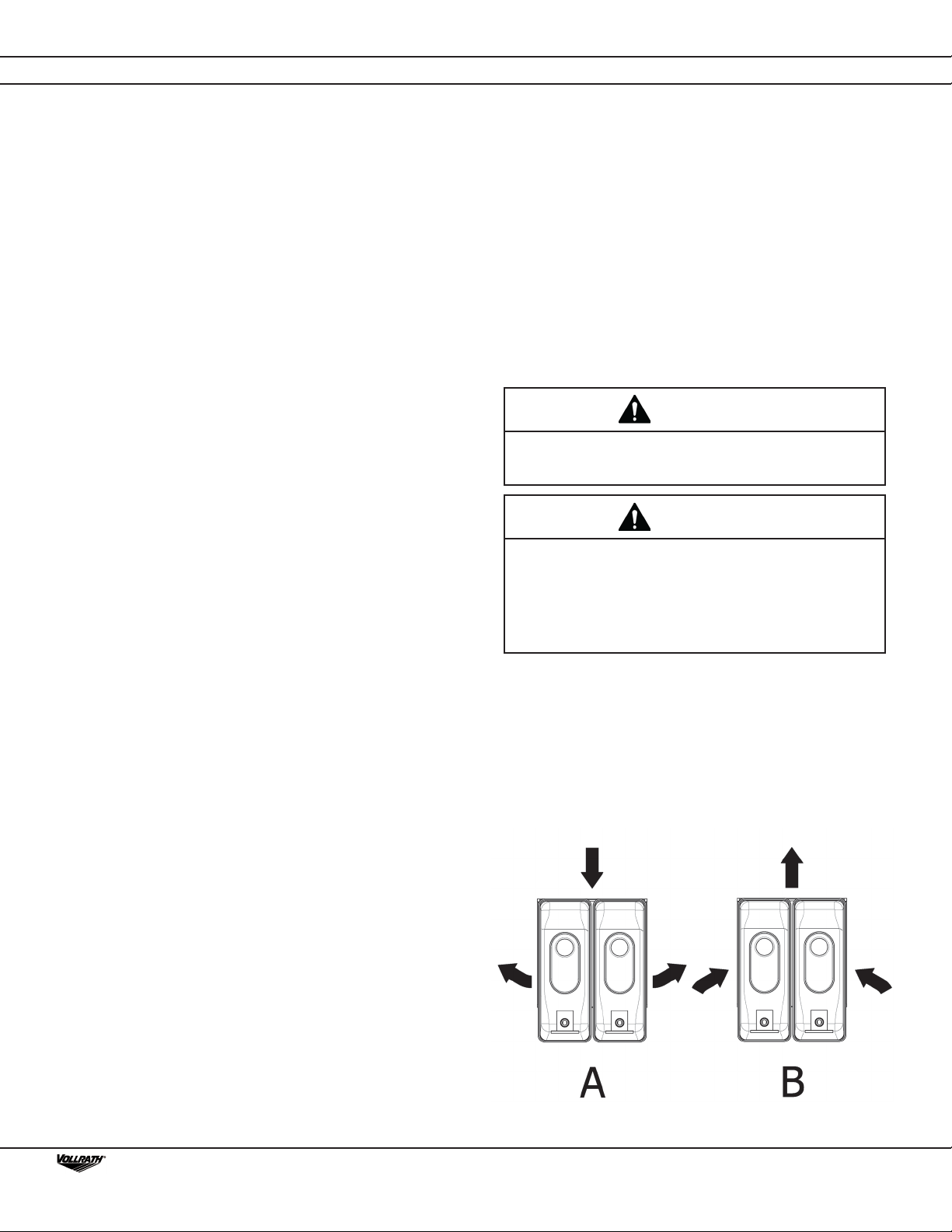
On 12L & 20L dispensers, the condenser is on the back of the
unit and air flow is from back to sides (A). To clean the condenser,
disconnect the power and remove the back panel.
On 8L dispensers, the condenser is also on the back of the unit,
but air flow if from sides to back (B). To clean the condenser,
disconnect the power and remove the faucet side panel to clean it
from the inside.