Voltronic Power 1KVA User manual

Axpert MKS 1~3KVA 24V Service manual
1
Axpert Charger/ Inverter
Service manual

Axpert MKS 1~3KVA 24V Service manual
2
Revision
Description
Prepared
by
Approved
by
V00
Initial draft release
Jing Fang
2013-06-10
Francis Fu
2013-06-11

Axpert MKS 1~3KVA 24V Service manual
3
Table of contents
1. General information.......................................................................................................................................... 4
1.1 Getting start............................................................................................................................................ 4
1.2 Important safety instructions ............................................................................................................... 4
2. Functional block................................................................................................................................................ 6
3. Working principle of the major functional block............................................................................................ 7
3.1 Switch Power Supply............................................................................................................................ 7
3.2 DC TO DC converter (push-pull)......................................................................................................... 8
3.3 DC TOAC inverter (full-bridge)........................................................................................................... 9
3.4 Charger................................................................................................................................................. 10
4. Functional explanations for each PCB......................................................................................................... 11
4.1 Main board........................................................................................................................................... 11
4.2 MPPT board......................................................................................................................................... 11
4.3 COMM board....................................................................................................................................... 11
4.4 LED board............................................................................................................................................ 12
5. Interface............................................................................................................................................................ 12
5.1 LED Indicator....................................................................................................................................... 12
5.2 LCD Display Icons .............................................................................................................................. 13
6. Troubleshooting............................................................................................................................................... 16
6.1 Fault Reference Code........................................................................................................................ 16
6.2 Warning Indicator................................................................................................................................ 17
6.3 Trouble shooting according to fault indication................................................................................ 17
6.4 Quick start............................................................................................................................................ 18
7. Test Step........................................................................................................................................................... 21
8. Electrical specification.................................................................................................................................... 22
Table 1 Line Mode Specifications................................................................................................................. 22
Table 2 Invert Mode Specifications............................................................................................................... 23
Table 3 Charge Mode Specifications............................................................................................................ 24

Axpert MKS 1~3KVA 24V Service manual
4
1. General information
1.1 Getting start
This manual is for Axpert MKS 1KVA-3KVA series, it can help service personal perform the basic
maintenance and repair service.
This manual focus on the service, so you should get the basic operation of the Inverter/Charger from the
user manual, and make sure you had read and understood user manual before you use this service
manual.
The manual include 8 sections, as follows
General Information, this section show you the general information of the service manual
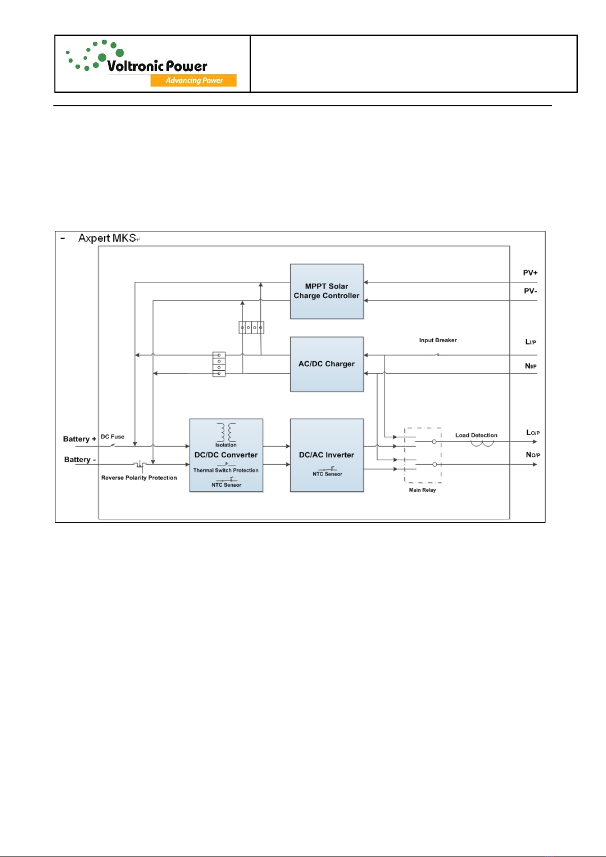
Functional Block, this section show you the major functional block of the Inverter/Charger
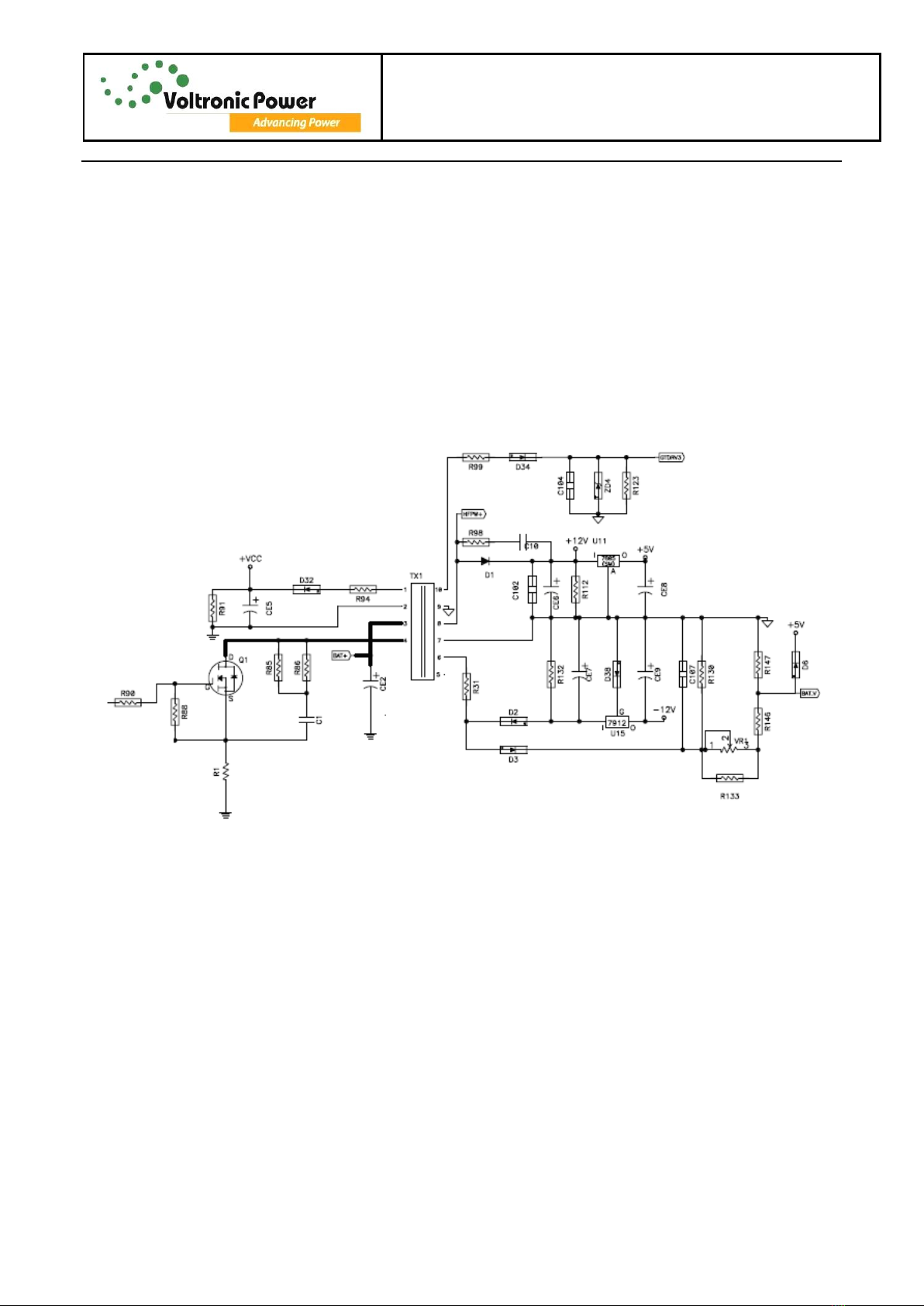
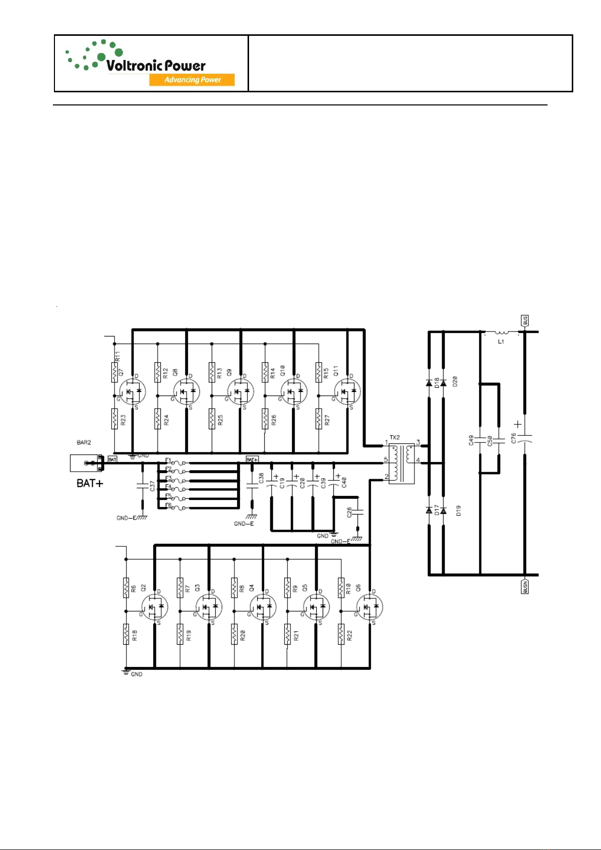
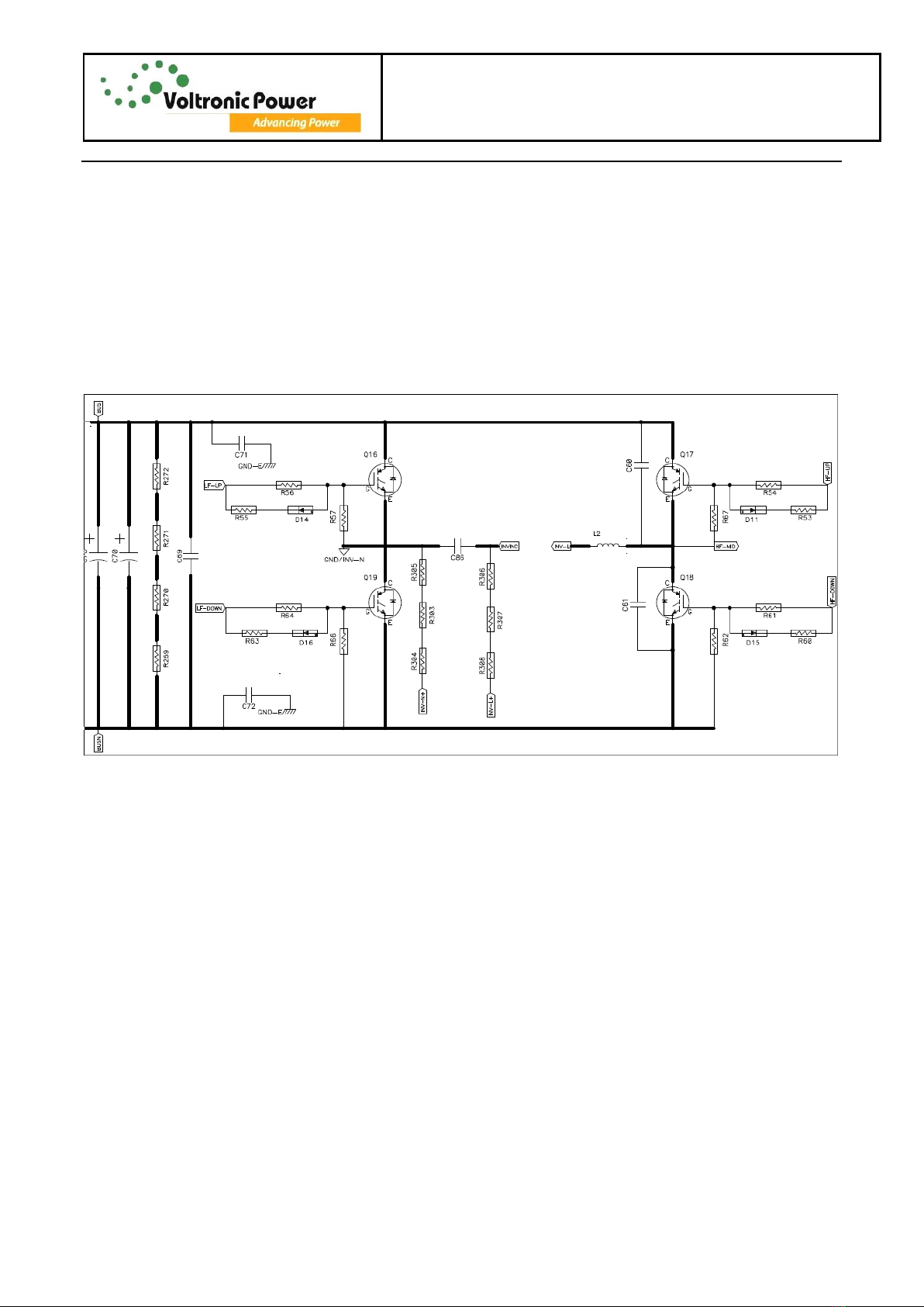
Working Principle of the major Functional Block, this section show you the major functional block
Function explanations for each PCB, this section show you all the PCBs of the Inverter/Charger
Interface, this section show you the LCD interface, include display and setting
Trouble shooting, this section will give you the way to find the trouble
Test step ,this section tell you how to test the Inverter/Charger after you repair the unit
Electric Specifications, this section show you the basic electric specification of the Inverter/Charger
1.2 Important safety instructions
WARNING: This chapter contains important safety and operating instructions. Read and
keep this manual for future reference.
1. Before using the unit, read all instructions and cautionary markings on the unit, the batteries and
all appropriate sections of this manual.
2. CAUTION --To reduce risk of injury, charge only deep-cycle lead acid type rechargeable batteries.
Other types of batteries may burst, causing personal injury and damage.
3. Do not disassemble the unit. Take it to a qualified service center when service or repair is required.
Incorrect re-assembly may result in a risk of electric shock or fire.
4. To reduce risk of electric shock, disconnect all wirings before attempting any maintenance or
cleaning. Turning off the unit will not reduce this risk.
5. CAUTION –Only qualified personnel can install this device with battery.
6. NEVER charge a frozen battery.
7. For optimum operation of this inverter/charger, please follow required spec to select appropriate
cable size. It’s very important to correctly operate this inverter/charger.

Axpert MKS 1~3KVA 24V Service manual
5
8. Be very cautious when working with metal tools on or around batteries. A potential risk exists to
drop a tool to spark or short circuit batteries or other electrical parts and could cause an explosion.
9. Please strictly follow installation procedure when you want to disconnect AC or DC terminals.
Please refer to INSTALLATION section of this manual for the details.
10. Fuses (40A, 32VDC *4pcs for 1KVA/2KVA and *6pcs for 3KVA) are provided as over-current
protection for the battery supply.
11. GROUNDING INSTRUCTIONS -This inverter/charger should be connected to a permanent
grounded wiring system. Be sure to comply with local requirements and regulation to install this
inverter.
12. NEVER causeAC output and DC input short circuited. Do NOT connect to the mains when DC
input short circuits.
13. Warning!! Only qualified service persons are able to service this device. If errors still persist after
following troubleshooting table, please send this inverter/charger back to local dealer or service
center for maintenance.

Axpert MKS 1~3KVA 24V Service manual
6
2. Functional block
Axpert MKS 1KVA-3KVA series production employ a double conversion topology, comprise following
functional blocks, as shown in figure 2.1
Figure 2.1 function block diagram

Axpert MKS 1~3KVA 24V Service manual
7
3. Working principle of the major functional block
3.1 Switch Power Supply
The switch power supply (SPS) supplies DC power for Inverter/Charger operation. The input voltage of
the SPS is the battery orAC Charger output voltage.
Figure 3.1 basic circuit of power supply
This is the fly-back DC-DC converter, fly-back operation can be easily recognized from the position of the
dots on the transformer primary and secondary(these dots show starts of the winds). When Q1 is ON, the
dot ends of all winds are negative with respect to their no-dot ends. Output rectifier diodes D1, D2, D32
and D34 are reverse-biased and all the output load currents are supplied from storage filter capacitors C1,
C2, C3 and C4.The primary coil of the transformer acts as an inductor and stored energy.
When Q1 is OFF, the stored energy in the primary coil is delivered to secondary filter capacitors CE5, CE6,
CE7and C104.
As shown in figure 3.1, this circuit may generate several output voltage, such as +12V,-12V, +VCC, +5V,
HFPW+, GTDRV3.

Axpert MKS 1~3KVA 24V Service manual
8
3.2 DC TO DC converter (push-pull)
The push-pull topology is a transformer isolated forward-mode regulator. Unlike the
Fly-back transformer, the push-pull transformer does not store any energy and output current is drawn
when either power switches (Q7-Q11 or Q2-Q6) is conducting.
A push-pull topology is shown in figure 3.2, power switch Q7-Q11 and Q2-Q6 receive 180 out-of-phases.
Refer to figure 3.2, the battery voltage is transformed through a push-pull DC-DC converter to >330Vdc
as DC BUS for inverter. When the line fails, the DC BUS voltage is caught up to supply the power needed
by the inverter immediately.
The output voltage (DCBUS) must be higher than the input voltage (BAT+) .It mentioned by the primary
turns and secondary turns. In this circuit, BAT+ =24VDC with MKS1000/2000/3000,DC BUS voltage
above 330Vdc.
Figure 3.2 Push-pull topology

Axpert MKS 1~3KVA 24V Service manual
9
3.3 DC TO AC inverter (full-bridge)
The Inverter circuit (Figure 3.3) and PWM control are only active under battery mode. The Inverter circuit
of Axpert MKS series is based on a full-bridge circuitry and its output is driven by photo-couplers. The
photo-couplers are capable to drive high energy and high speed power of MOSFET and IGBT with
independent high and low referenced output channels.
To construct a high frequency PWM inverter, the drivers receive switching signals from PWM generation
circuit through a pair of photo-couplers to trigger the upper IGBT and the lower IGBT alternately. The
output of IGBT's is filtered by an LC circuit to reduce the o/p voltage harmonics distortion.
Figure 3.3 Full-bridge topology

Axpert MKS 1~3KVA 24V Service manual
10
3.4 Charger
The Charger of utility is to recharge and maintain the batteries at fully charged condition .The charger
charges the batteries with a constant current at initial stage, and as battery voltage keep increasing, the
charge current decrease accordingly until the charge voltage reached the constant voltage level, and then
the charger turn to the floating charge mode.
As shown in figure 3.4, the charger also employed a fly-back topology like the SPS.
Figure 3.4 Charger fly-back topology

Axpert MKS 1~3KVA 24V Service manual
11
4. Functional explanations for each PCB
Item
Series name
PCB name
PCB serial number
Quantity
Remark
1
MKS-1000-24
Main
71-500324-XXG
1
2
MPPT
71-600084-XXG
1
3
COMM
71-500237-XXG
1
4
LED
71-500238-XXG
1
5
MPPT COMM
71-500323-XXG
1
6
MKS-2000-24
Main
71-500349-XXG
1
Item 2~5 is
common
used PCBA.
7
MKS-2000-24
Main
71-500348-XXG
1
Note: “XX” in the serial number is the version of the PCB.
4.1 Main board
The main board consists of SPS, DC-DC converter, inverter, charger, MCU control. Many semiconductors
and easy-failure components on the board, so it should be play more attention when the system is
abnormal.
4.2 MPPT board
The MPPT solar charge controller uses PWM-based DSP controller to keep batteries regulated and
prevent batteries from overcharging and discharging.Applying intelligent MPPT algorithm, it allows MPPT
solar charge controller to extract maximum power from solar arrays by finding the maximum power point
of the array.
4.3 COMM board
This inverter/charger is equipped with a communication port to communicate with a PC with
corresponding software. Please use supplied communication cable to connect to communication port of
this inverter and RS-232 port of the PC.

Axpert MKS 1~3KVA 24V Service manual
12
4.4 LED board
The LED display panel includes there indicators and four functional keys.
5. Interface
The operation and display panel, shown in below chart, is on the front panel of the inverter. It includes
three indicators, four function keys and a LCD display, indicating the operating status and input/output
power information.
5.1 LED Indicator
LED Indicator
Messages
Green
Solid On
Output is available in bypass mode
Flashing
Output is powered by battery in inverter mode
Green
Solid On
Battery is fully charged
Flashing
Battery is charging.
Red
Solid On
Fault mode
Flashing
Warning mode
LCD display
LED indicators
Function keys

Axpert MKS 1~3KVA 24V Service manual
13
Function Keys
Function Key
Description
ESC
Exit setting mode
UP
To previous selection
DOWN
To next selection
ENTER
To confirm the selection in setting mode or enter setting mode
5.2 LCD Display Icons
Icon
Function description
Input Source Information
Indicates the AC input.
Indicates the PV input
Indicate input voltage, input frequency, PV voltage, battery voltage and
charger current.
Configuration Program and Fault Information
Indicates the setting programs.
Indicates the warning and fault codes.
Warning: flashing with warning code.
Fault: lighting with fault code
Output Information
Indicate output voltage, output frequency, load percent, load in VA and
load in Watt.

Axpert MKS 1~3KVA 24V Service manual
14
Battery Information
Indicates battery level by 0-24%, 25-49%, 50-74% and 75-100% in battery
mode and charging status in line mode.
In AC mode, it will present battery charging status.
Status
Battery voltage
LCD Display
Constant
Current mode
/ Constant
Voltage mode
<2V/cell
4 bars will flash in turns.
2 ~ 2.083V/cell
Bottom bar will be on and the other three
bars will flash in turns.
2.083 ~ 2.167V/cell
Bottom two bars will be on and the other
two bars will flash in turns.
> 2.167 V/cell
Bottom three bars will be on and the top
bar will flash.
Floating mode. Batteries are fully charged.
4 bars will be on.
In battery mode, it will present battery capacity.
Load Percentage
Battery Voltage
LCD Display
Load >50%
< 1.717V/cell
1.717V/cell ~ 1.8V/cell
1.8 ~ 1.883V/cell
> 1.883 V/cell
50%> Load > 20%
< 1.817V/cell
1.817V/cell ~ 1.9V/cell
1.9 ~ 1.983V/cell
> 1.983
Load < 20%
< 1.867V/cell
1.867V/cell ~ 1.95V/cell
1.95 ~ 2.033V/cell
> 2.033

Axpert MKS 1~3KVA 24V Service manual
15
Load Information
Indicates overload.
Indicates the load level by 0-24%, 25-50%, 50-74% and 75-100%.
0%~25%
25%~50%
50%~75%
75%~100%
Mode Operation Information
Indicates unit connects to the mains.
Indicates unit connects to the PV panel.
Indicates load is supplied by utility power.
Indicates the utility charger circuit is working.
Indicates the DC/AC inverter circuit is working.
Mute Operation
Indicates unit alarm is disabled.

Axpert MKS 1~3KVA 24V Service manual
16
6. Troubleshooting
This section describes how to find the trouble when the system is abnormal. We suggest you can follow
the service procedure:
a. Check the system status by LED and LCD display, the sounds of buzzer.
b. Observe the failure board, static checking.
c. Replace the failure components.
d. Static checking.
e. Power up checking.
f. Test after repair.
Following section will help service person to solve most of problem.
6.1 Fault Reference Code
Fault Code
Fault Event
Icon on
01
Fan is locked
02
Over temperature
03
Battery voltage is too high
04
Battery voltage is too low
05
Output short circuited or Over temperature
06
Output voltage is abnormal
07
Over load time out
08
Bus voltage is too high
09
Bus soft start failed
11
Main relay failed

Axpert MKS 1~3KVA 24V Service manual
17
6.2 Warning Indicator
Warning
Code
Warning Event
Audible Alarm
Icon flashing
01
Fan is locked
Beep three times every
second
03
Battery is over charged
Beep once every 1second
04
Low battery
Beep once every 1
second
07
Overload
Beep once every 0.5
second
10
Power limitation
Beep twice every 3
seconds
12
MPPT Stop charging
as battery too low
13
MPPT charger PV voltage
high loss
14
MPPT charger overload
fault
6.3 Trouble shooting according to fault indication
Problem
LCD/LED/Buzzer
Explanation / Possible cause
What to do
Unit shuts down
automatically
during startup
process.
LCD/LEDs and
buzzer will be active
for 3 seconds and
then complete off.
The battery voltage is too low
(<1.91V/Cell)
1. Re-charge battery.
2. Replace battery.
No response after
power on.
No indication.
1. The battery voltage is far too
low. (<1.4V/Cell)
2. Battery polarity is connected
reversed.
1. Check if batteries and the
wiring are connected well.
2. Re-charge battery.
3. Replace battery.
Mains exist but the
unit works in
battery mode.
Input voltage is
displayed as 0 on
the LCD and green
LED is flashing.
Input protector is tripped
Check if AC breaker is
tripped and AC wiring is
connected well.
Green LED is
flashing.
Insufficient quality of AC power
(Shore or Generator)
1. Check if AC wires are too
thin and/or too long.
2. Check if generator (if
applied) is working well, or

Axpert MKS 1~3KVA 24V Service manual
18
check if input voltage range
setting is correct
(UPSAppliance)
Green LED is
flashing.
Set Solar power as the priority of
output source
Change output source
priority to Utility first.
When the unit is
turned on, internal
relay is switched
on and off
repeatedly.
LCD display and
LEDs are flashing.
Battery is disconnected.
Check if battery wires are
connected well.
Buzzer beeps
continuously and
red LED is on.
Fault code 07.
Overload error. The inverter is
loaded with more than 110%
load and time is up
Reduce the connected load
by switching off some
equipment.
Fault code 05.
Output short circuited.
Check if wiring is connected
well and remove abnormal
load.
Temperature of internal
converter component is over
120°C.
Check whether the air flow
of the unit is blocked or
whether the ambient
temperature is too high.
Fault code 02.
Internal Inverter component over
100°C
Fault code 03.
Battery is over charged.
Return to repair center.
The battery voltage is too high.
Check if spec and quantity
of batteries are meet
requirements.
Fault code 01.
Fan fault
Replace the fan.
Fault code 06.
Output abnormal (Inverter
voltage below than 190Vac or is
higher than 260Vac)
1. Reduce the connected
load.
2. Return to repair center
Fault code 08.
Internal components failed.
Return to repair center
Fault code 09.
6.4 Quick start
Before any detail check of the system, please check the components listed as follow table.
NOTE: It is important to check the capacitor’s voltage on the board lower than the safety voltage before
any check action.

Axpert MKS 1~3KVA 24V Service manual
19
Functional
block
Checked components
Instruction
function
Reference value
Failed status
DC-DC
Converter
Fuse
F1---F6
Resistance
0.14 ohm
short or open
MOSFET(IRF1407/IRF3205)
Q2---Q11
Resistance
310k DS
short or open
290k GD
short or open
4k GS
short or open
Diode(RHRP1560/RHRP860)
D17---D20
Resistance
165k
short or open
Driver IC
TC4427
Resistance
4.8K PIN6-PIN3
short or open
Resistance
R6---R15
Resistance
10 ohm
short or open
DC-AC
Inverter
IGBT(STGW45HF60WD)
Q16---Q19
Resistance
178K-200K DS
short or open
220K-250K GD
short or open
50K GS
short or open
Resistance
R54,R56,R61,R64
Resistance
100 ohm
short or open
Photo-coupler
U24---U27
Resistance
2K
short or open
Charger
Rectifier
REC1
Resistance
0.5M
PIN1-PIN2
short or open
0.43M
PIN1-PIN3
short or open
160K
PIN1-PIN4
short or open
MOSFET(2SK3878)
Q20---Q22
Resistance
162K DS
short or open
210K GD
short or open
12K GS
short or open
Diode(MBR20200)
D21---D23
Resistance
>4M K->A
short or open
Resistance
78K A->K
short or open
Control IC
UC3843
Resistance
>4K
PIN5-PIN7
short or open
Resistance
R258,R260,R262
Resistance
100 ohm
short or open
S.P.S
Control IC
UC3845
Resistance
>4K
PIN5-PIN7
short or open
Diode
D2,D3,D32,D34
Resistance
>4K
short or open
D1
Resistance
3.5K
short or open
Resistance
R31,R94,R99
Resistance
2.2 ohm
short or open
MPPT
MOSFET
Q1,Q2
Resistance
430ohm DS
short or open
>1M GD
short or open
0.618K GS
short or open
MOSFET
Q3,Q7
Resistance
256ohm DS
short or open
>0.5M GD
short or open
32.92K GS
short or open

Axpert MKS 1~3KVA 24V Service manual
20
MOSFET
Q5,Q6
Resistance
430ohm DS
short or open
>1M GD
short or open
0.618K GS
short or open
MOSFET
Q27,Q37,Q29,Q39
Resistance
448ohm DS
short or open
>1M GD
short or open
100K GS
short or open
Other manuals for 1KVA
1
This manual suits for next models
2
Table of contents