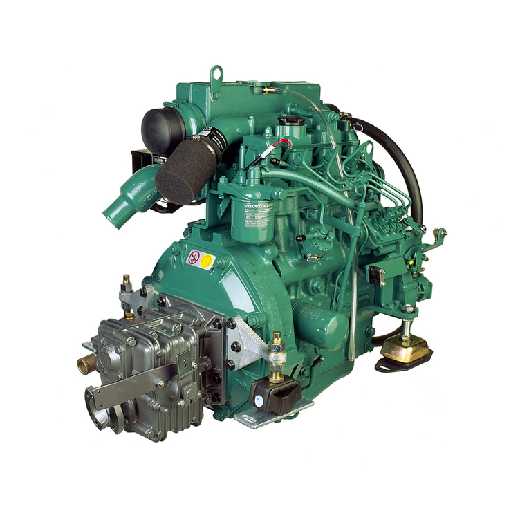
Volvo D1-13 B Instruction manual

Workshop manual
Group 30
A
2(0)
D1-13 B • D1-20 B
D1-30 B • D2-40 B
D2-55 D • D2-55 E
D2-75 B • D2-75 C
https://www.boat-manuals.com/

https://www.boat-manuals.com/

Group 30 Electrical system
Marine Diesel engines
D1-13 B • D1-20 B
D1-30 B • D2-40 B
D2-55 D • D2-55 E
D2-75 B • D2-75 C
© 2007 AB VOLVO PENTA
We reserve the right to make modifications without prior notice.
Printed on environmentally compatible paper.
Contents
Safety information ..................................................2
Introduction...............................................................2
Important ..................................................................2
General information ...............................................5
About this Workshop Manual....................................5
Spare parts...............................................................5
Certified engines.......................................................5
Repair instructions.................................................6
Our common responsibility .......................................6
Torque ......................................................................6
Special tools ...........................................................7
The MDI system ......................................................8
Component location...............................................9
Component description ....................................... 11
MDI......................................................................... 11
Switch, oil pressure, engine.................................... 11
Sensor, coolant temperature .................................. 11
Sensor, engine speed (flywheel) ............................ 11
Stop solenoid..........................................................12
Glow plugs..............................................................12
Starter motor ..........................................................12
Alternator................................................................13
Repair instructions...............................................14
General advice .......................................................14
Fault tracing of cables and connectors ...................14
Starter motor ..........................................................15
Checking battery voltage ........................................15
Checking alternator brushes...................................16
Checking the charging system................................18
Checking the instruments .......................................19
Malfunctions .........................................................20
Oil pressure (engine) warning.................................21
Check MDI output for oil pressure switch ...........22
Coolant temperature warning .................................23
Check MDI output for coolant
temperature sensor ............................................25
Check coolant temperature sensor.....................26
Multilink fault...........................................................27
Check speed sensor, flywheel............................29
Check NMEA 2000 Gateway LED ......................30
Fuel level warning...................................................31
Check fuel level sensor ......................................32
Button panel fault....................................................33
Check button panel.............................................34
Stop solenoid fault ..................................................35
Check stop solenoid ...........................................36
Start / preheat warning ...........................................37
Battery warning ......................................................40
Check altenator excitation voltage......................41
Wiring diagram .....................................................42
Pin configuration, MDI .........................................43
Technical data ......................................................44
Electrical system ....................................................44
Alternator................................................................44
Starter motor ..........................................................44
https://www.boat-manuals.com/

Safety information Group 30: Electrical system
2
Safety information
Important
In this book and on the product you will find the fol-
lowing special warning symbols.
WARNING! Warns for the risk of personal inju-
ry, major damage to product or property, or se-
rious malfunctions if the instruction is ignored.
IMPORTANT! Is used to call attention to things
which could cause damage or malfunctions to
product or property.
NOTE! Is used to call attention to important informa-
tion, to facilitate work processes or operation.
To give you a overview of the risks which always
need to be observed and precautions which always
have to be taken, we have noted them below.
Make it impossible to start the engine by cutting
system current with the main switch(es)and lock
it (them) in the off position before starting ser-
vice work. Set up a warning notice by the helm
station.
As a general rule all service operations must be
carried out with the engine stopped. Some
tasks, such as adjustments, need the engine to
be running, however. Approaching an engine
which is operating is a safety hazard. Remem-
ber that loose clothing or long hair can get
caught in rotating parts and cause serious per-
sonal injury.
Introduction
This workshop manual contains technical data, de-
scriptions and repair instructions for the Volvo Penta
products or product versions noted in the table of
contents. Check that you have the correct Workshop
Manual for your engine.
Read this safety information and the General Informa-
tion and Repair Instructions in the workshop manual
carefully before starting work.
If work is done adjacent to a running engine, a care-
less movement or a dropped tool can lead to personal
injury in the worst case.
Take care to avoid contact with hot surfaces (exhaust
pipes, Turbocharger, air intake pipe, starter heater
etc.) and fluids in pipes and hoses in an engine which
is running or has just been stopped. Reinstall all pro-
tective parts removed during servicework before
starting the engine.
Never start the engine with the cover removed.
Apart from the risk of spilling oil, there is a risk
of personal injury.
Check that the warning or information labels on
the product are always clearly visible. Replace
labels which have been damaged or painted
over.
Never start the engine without installing the air
cleaner filter. Foreign objects entering the in-
take ducts can cause mechanical damage.
Never use start spray or similar products as a
starting aid. They may cause an explosion in
the inlet manifold. Danger of personal injury.
Avoid opening the coolant filling cap when the
engine is hot. Steam or hot coolant can spray
out and the system pressure will be lost. Open
the filler cap slowly, and release the pressure in
the cooling system if the filling cap or tap has to
be opened, or if a plug or coolant hose has to
be removed when the engine is hot. It is difficult
to anticipate in which direction steam or hot
coolant can spray out.
Hot oil can cause burns. Avoid skin contact with
hot oil. Ensure that the lubrication system is not
under pressure before carrying out any work.
Never start or operate the engine with the oil fill-
er cap removed, otherwise oil could be ejected.
Stop the engine and close the sea cocks before
doing any work on the cooling system.
https://www.boat-manuals.com/

Group 30: Electrical system Safety information
3
Only start the engine in a well- ventilated area.
When operated in a confined space, exhaust
fumes and crankcase gases must be ventilated
from the engine bay or workshop area.
Always use protective glasses or goggles when
carrying out work where there is a risk of splin-
ters, grinding sparks, acid splashes or where
other chemicals are used. Your eyes are ex-
tremely sensitive, injury could cause blindness!
Avoid getting oil on your skin! Repeated expo-
sure to oil or exposure over a long period can
result in the skin becoming dry. Irritation, dry-
ness and eczema and other skin problems can
then occur.
Used oil is more dangerous than fresh oil from a
health aspect. Use protective gloves and avoid
oilsoaked clothes and rags. Wash regularly, es-
pecially before eating. There are special skin
creams which counteract drying out of the skin
and make it easier to clean off dirt after work is
completed.
Most chemicals intended for the product (e.g.
engine and transmission oils, glycol, petrol
(gasoline) and diesel oil) or chemicals for work-
shop use (e.g. degreasers, paints and solvents)
are hazardous. Read the instructions on the
product packaging with care! Always follow the
safety precautions for the product (for example
use of protective mask, glasses, gloves etc.).
Make sure that other personnel are not inad-
vertently exposed to hazardous chemicals, for
example in the air. Ensure good ventilation in
the work place. Follow the instructions provided
when disposing of used or leftover chemicals.
Exercise extreme care when leak detecting on
the fuel system and testing the fuel injector noz-
zles. Use eye protection. The jet which comes
from a fuel injector has very high pressure and
considerable penetrationability. Fuel can force
its way deep into body tissue and cause severe
injury. Danger of blood poisoning (septicemia).
All fuels, and many chemicals, are flammable.
Do not allow naked flame or sparks in the vicini-
ty. Petrol (gasoline), some thinners and hydro-
gen gas from batteries are extremely flammable
and explosive when mixed with air in the correct
ratio. No Smoking! Ensure that the work area is
well ventilated and take the necessary safety
precautions before starting welding or grinding
work. Always ensure that there are fire extin-
guishers at hand when work is being carried
out.
Make sure that oil and fuel soaked rags, and
used fuel and oil filters are stored in a safe
place. Rags soaked in oil can spontaneously ig-
nite under certain circumstances.
Used fuel and oil filters are polluting waste and
must be handed to an approved waste manage-
ment facility for destruction, together with used
lubrication oil, contaminated fuel, paint residue,
solvents, degreasers and wash residue.
Batteries must never be exposed to open
flames or electric sparks. Never smoke close to
the batteries. The batteries generate hydrogen
gas when charged, which forms an explosive
gas when mixed with air. This gas is easily ignit-
ed and highly volatile. A spark, which can be
caused by incorrect battery connection, can
cause an explosion with resulting damage. Do
not move the connections when you attempt to
start the engine (risk of arcing), and do not
stand and lean over one of the batteries.
Always ensure that the Plus (positive) and Mi-
nus (negative) battery cables are correctly in-
stalled on the corresponding terminal posts on
the batteries. Incorrect installation can result in
serious damage to the electrical equipment. Re-
fer to the wiring diagram.
Always use protective goggles when charging
and handling the batteries. Battery electrolyte
contains sulfuric acid which is highly corrosive.
Should the battery electrolyte come into contact
with unprotected skin wash off immediately us-
ing plenty of water and soap. If you get battery
acid in your eyes, flush at once with a generous
amount of water, and get medical assistance at
once.
Turn the engine off and turn off the power at the
main switch(es) before carrying out work on the
electrical system.
Clutch adjustments must be carried out with the
engine stopped.
The existing lugs on the engine/reversing gear
should be used for lifting the assembly.
Always check that the lifting devises are in good
condition and that they have the correct capaci-
ty for the lift (the weight of the engine plus the
reversing gear and extra equipment).
https://www.boat-manuals.com/

Safety information Group 30: Electrical system
4
The engine should be lifted with a customized
or adjustable lifting boom for safe handling and
to avoid damaging components on top of the
engine. All chains or cables should be parallel
to each other and should be as square as pos-
sible to the top of the engine. If other equipment
connected to the engine has altered its center
of gravity, special lifting devises may be needed
to obtain the correct balance and safe handling.
Never do any work on an engine which just
hangs from a liftingdevise.
Never work alone when removing heavy engine
components, even when using lifting devices
such as locking tackle lifts. When using a lifting
device two people are usually required to do the
work, one to take care of the lifting device and
another to ensure that components are lifted
clear and not damaged during the lifting opera-
tions.
When you work aboard a boat, always make
sure that there is enough space for disassembly
where you are working, with no risk of personal
injury or material damage.
Components in the electrical and fuel systems
on Volvo Penta products have been designed
to minimize the risks of explosion and fire. The
engine must not be run in areas where there
are explosive materials.
WARNING! Fuel delivery pipes must not be
bent or straightened under any circumstances.
Damaged pipes must be replaced.
Remember the following when washing with a
high pressure washer: Never aim the water jet
at seals, rubber hoses or electrical components.
Never use a high pressure washer for engine
cleaning.
Only use the fuels recommended by Volvo Pen-
ta. Refer to the Instruction Book. Use of fuels
that are of a lower quality can damage the en-
gine. Poor fuel can also lead to higher-
maintenance costs.
https://www.boat-manuals.com/
Group 30: Electrical system Safety information
5
General information
About this Workshop Manual
This workshop manual contains, descriptions and re-
pair instructions for the engines equiped with MDI.
The workshop manual can illustrate tasks done on
any of the engines noted above. This means that the
illustrations and photographs which clarify certain de-
tails might not correspond with other engines in some
cases. Repair methods are similar in all important re-
spects, however. If this is not the case, this is noted.
Important differences are noted separately.
The engine designation and number are noted on the
number plate and engine decal. The engine designa-
tion and number must always be given in all corre-
spondence about any product.
The Workshop Manual is produced primarily for the
use of Volvo Penta workshops and service techni-
cians. This assumes that people who use the Manual
have basic knowledge of marine drive systems and
can do the tasks of a mechanical or electrical nature
associated with the trade.
Volvo Penta constantly improves its products, so we
reserve the right to make modifications without prior
notification. All information in this manual is based on
product data which was available up to the date on
which the manual was printed. Any material changes
introduced into the product or service methods after
this date are notified by means of Service Bulletins.
Spare parts
Spare parts for electrical- and fuel systems are sub-
ject to various national safety requirements, such as
U.S. Coast Guard Safety Regulations. Volvo Penta
Original Spare Parts meet these specifications. Any
damage, occasioned by use of non-original Volvo
Penta spares for the product, will be not be compen-
sated by the warranty offered by Volvo Penta.
Certified engines
When doing service and repair on emission certi-
fied engines, it is important to be aware of the fol-
lowing:
Certification means that an engine type has been
checked and approved by the relevant authority. The
engine manufacturer guarantees that all engines made
of the same type are equivalent to the certified engine.
This makes special demands on service and re-
pair work, as follows:
●Maintenance and service intervals recommended
by Volvo Penta mustbe complied with.
●Only Volvo Penta original spares may be used.
●Service to injection pumps, pump settings and in-
jectors must always be done by an authorized
Volvo Penta workshop.
●The engine must not be converted or modified,
except for the accessories and service kits which
Volvo Penta has approved for the engine.
●No installation changes to the exhaust pipe and
engine air inlet ducts may be done.
●No seals may be broken by unauthorized person-
nel.
The general advice in the instruction book about op-
eration, care and maintenance applies.
IMPORTANT! Delayed or inferior care/mainte-
nance, and the use of non-original spares,parts
means that AB Volvo Penta can no longer be
responsible for guaranteeing that the engine
complies with the certified version.
Damage and/or costs which arise from this will
not be compensated by Volvo Penta.
https://www.boat-manuals.com/
Repair instructions Group 30: Electrical system
6
Repair instructions
WARNING!
IMPORTANT!
NOTE!
The warning signs which occur in the workshop manu-
al (please refer to “Safety information” for their mean-
ings)
are not comprehensive in any way, since we can not of
course foresee everything, because service work is
done in highly varying circumstances. For this reason,
all we can do is to point out the risks which we believe
could occur due to incorrect work in a well-equipped
workshop, using work methods and tools tested by us.
All operations described in the Workshop Manual for
which there are Volvo Penta Special Tools available
assume that these tools are used when carrying out
the repair. Volvo Penta Special Tools have been de-
veloped to ensure the most safe and rational working
methods possible. It is therefore the responsibility of
anyone using other tools or other working methods
than we recommend to determine that there is no risk
of personal injury or mechanical damage or malfunc-
tion as a result.
In some cases special safety precautions and user in-
structions may be required in order to use the tools
and chemicals mentioned in the Workshop Manual.
These rules must always be observed, so there are no
special instructions about this in the workshop manual.
By following these basic recommendations and using-
using common sense it is possible to avoid most of
the risks involved in the work. A clean work place and
a clean engine will eliminate many risks of personal
injury and engine malfunction.
Above all, when work on fuel systems, lubrication
systems, induction systems, bearing caps and seals
is done, it is extremely important that no dirt or other
kinds of foreign particles are able to get in, since this
would otherwise cause malfunctions or shortened re-
pair life.
Our common responsibility
Each engine consists of a large number of collaborat-
ing systems and components. Any deviation of a
component from its technical specification can dra-
matically increase the environmental impact of an
otherwise good engine. For this reason, it is important
that the specified wear tolerances are observed, that
systems which are adjustable are correctly adjusted
and that Volvo Penta Original Spares are used for the
engine. The stated service intervals in the Mainte-
nance Schedule must be observed.
Some systems, such as the components in the fuel
system, require special expertise and special testing
equipment for service and maintenance. For environ-
mental reasons etc., some components are sealed at
the factory. It is only permissible to work on sealed
components if you are authorized to do such work.
Remember that most chemical products, incorrectly
used, damage the environment. Volvo Penta recom-
mends the use of biodegradable degreasers whenever
engine components are de-greased, unless otherwise
specified in the workshop manual. When working on-
board a boat, be careful to ensure that oils, wash resi-
due etc. are processed for destruction, and are not inad-
vertently discharged with bilge water into the environ-
ment.
Torque
The tightening torque for vital fasteners, which should
be tightened with a torque wrench, are listed in “Tech-
nical Data: Special tightening torques” and noted in
the job descriptions in the book. All torque specifica-
tions apply to clean screws, screw heads and mating
faces. Torque data stated apply to lightly oiled or dry
threads. If lubricants, locking fluids or sealants are
needed on a fastener, the type of preparation to be
used will be noted in the job description. For fasten-
ers where specific torque values are not given,
please refer to “Technical data: General tightening
torques”. General torque specifications are target val-
ues and the fastener does not need to be tightened
with a torque wrench.
https://www.boat-manuals.com/

Group 30: Electrical system Repair instructions
7
Special tools
9812519 Multimeter
88890016 Adapter cable
9998699 Measurebox
9812519 88890016 9998699
https://www.boat-manuals.com/
Design and function Group 30: Electrical system
8
The MDI system
The MDI is located on the engine and is connected to
a number of nearby components, such as sensors,
switches, button panel andinstruments.
A data link (CAN bus) links the MDI to the tachome-
ter/display and other optional equipment such as
NMEA2000 interface, multisensor.
Functionality
Instrumentation
The instruments use a serial communication bus. The
serial communication bus in combination with EVC
reduces wiring and simplifies installation.
EVC system tachometer
All alarms are available in the tachometer. The ta-
chometer has a built in buzzer alarm and an output to
the instrument serial bus (easy-link).
EVC system display
The EVC system display is a complement or replace-
ment for the EVC system tachometer and optional in-
struments. The display shows operation information,
information messages and alarms. The user selects
what operation information to display with the buttons
on the display. The EVC system display can show
more than one operation information at one and the
same time. The display also has access to the same
display mode and calibration functions as for the EVC
system tachometer display.
Fuel level
If a fuel level gauge is used it must be connected to
the instrument serial communication bus (easy-link).
The MDI has an input for the fuel level sender.
NMEA support
The MDI system supports NMEA 2000 by means of a
hardware interface.
Boat speed, echo sounder and water temp
(Multisensor)
The multisensor is connected to the multilink cable.
Data from the multisensor are shown in the EVC dis-
play and the speedometer instrument.
https://www.boat-manuals.com/

Group 30: Electrical system Design and function
9
Component location
Basic instrumentation
De luxe instrumentation
https://www.boat-manuals.com/
Design and function Group 30: Electrical system
10
1. Glow plugs
2. Stop solenoid
3. Coolant temperature sensor
4. MDI
5. Starter relay
6. Glowplug relay
7. Charge sensing resistor
8. Starter motor
9. Alternator
10. Oil pressure switch
11. Engine speed sensor
2
98
11 10
15, 6, 7
34
NOTE! The engine on these pictures is a D1-13
but the component location is the same on D1-
20, D1-30, D2-40, D2-55, D2-75.
https://www.boat-manuals.com/

Group 30: Electrical system Component description
11
Sensor, engine speed (flywheel)
The sensor is located on top of the flywheel housing.
The sensor is inductive. It reads the crankshaft speed
by means of milled slots on the outer radius of the fly-
wheel.
The signal is sent to the MDI, which calculates the
engines revolution speed.
Component description
MDI
The MDI* is connected to sensors and switches on
the engine. The MDI uses easylink instruments and/
or the Volvo Penta EVC display to present informa-
tion.
To the MDI a button panel is connected that controls
the start and stop function of the engine.
*MDI = ”Mechanical diesel interface”.
Switch, oil pressure, engine
Oil pressure is observed by a pressure switch in-
stalled in the engine block on the right side of the en-
gine. The switch is “normally open” in normal opera-
tion. If the oil pressure is too low, the switch closes.
When the engine is not running the switch is closed.
Sensor, coolant temperature
The sensors are located on the left side of the engine.
The sensor senses the engine coolant temperature
and sends the information to the MDI. The sensor
consists of a non-linear resistor, whose resistance
varies with coolant temperature. The resistance falls
as the coolant temperature rises.
https://www.boat-manuals.com/
Component description Group 30: Electrical system
12
Stop solenoid
The stop solenoid is an electromagnetic relay. When
the stop button is pushed the stop solenoid is activat-
ed by the MDI. The stop solenoid shuts off the fuel
supply at the injection pump.
Starter motor
The starter motor is a DC series motor. The starter
pinion is operated by a control solenoid and can be
slid axially on the rotorshaft.
The starter motor has a reduction gear, which makes
it possible to obtain greater torque.
The starter motor power depends on the engine it is
fitted to, please refer to the table below.
D1-13, D1-20 0.8 kW
D1-30 1.1 kW
D2-40 1.4 kW
D2-55, D2-27 2.0kW
Glow plugs
One glowplug per cylinder is installed in the cylinder
head. All glowplugs are electrically connected by a
conductor rail. The glowplugs heat the air mixture
during starting.
https://www.boat-manuals.com/
Group 30: Electrical system Component description
13
Alternator
The alternator provides alternating current (14V/
115A).
The voltage regulator on the alternator is provided
with a sense system.
The sense system compares the charge voltage be-
tween the alternator terminals, B+ and B-, with the
voltage across the battery positive and negative ter-
minals. The voltage regulator then compensates for
any voltage drop in the cables between the alternator
and the batteries, by increasing the charge voltage
supplied by the alternator as necessary.
https://www.boat-manuals.com/

Repair instructions Group 30: Electrical system
14
Repair instructions
General advice
The following advice must be followed to avoid dam-
age to the MDl unit and other electronics.
IMPORTANT! The system must be disconnect-
ed from system voltage (by cutting the current
with the main switch) when the MDI connectors
are disconnected or connected.
Never disconnect the current with the main switch-
es when an engine is running.
Never undo a battery cable when the engine is
running.
Turn the main switches off or disconnect the bat-
tery cables during quick charging of the batteries.
NOTE! During normal floating charging, it is not
necessary to turn the main switches off.
Only batteries may be used for start help. A help
start device can produce a very high voltage and
damage the control unit and other electronics.
If a connector is disconnected from a sensor, be
very careful to avoid allowing the contact pins to
come into contact with oil, water or dirt.
Fault tracing of cables and
connectors
Special tools: 9812519
Check all connectors visually
Check the following:
●Look for oxidation which can impair contact in con-
nectors.
●Check that terminals are undamaged, that they
are correctly inserted into their connectors, and
that the cable is correctly terminated in the termi-
nal.
●If possible, shake the cables and pull the connec-
tors during measurement to discover whether the
cable harness is damaged.
●Check that the cables are not damaged. Avoid
clamping cables in tight bends close to the con-
nector.
Contact problems
Intermittent contact or temporary recurring faults can
be difficult to fault trace, and are frequently caused by
oxidation, vibration or poorly terminated cables.
Wear can also cause faults. For this reason, avoid
disconnecting a connector unless it is necessary.
Other contact problems can be caused by damage to
pins, sockets and connectors etc.
Shake cables and pull connectors during measure-
ment, to find where the cable is damaged.
Contact resistance and oxidation
Resistance in connectors, cables and junctions
should be 0 Ω. A certain amount of resistance will oc-
cur, however, because of oxidation in connectors.
If this resistance is too great, malfunctions occur. The
amount of resistance that can be tolerated before
malfunctions occur varies, depending on the load in
the circuit.
Open circuit
Possible reasons for faults could be chafed or broken
cables, or connectors which have come undone.
Use the wiring diagram to check the cables which are
relevant to the function. Start off with the most proba-
ble cable in the circuit.
Check the following:
●Disconnect the relevant connector at each end of
the cable harness.
●Use multimeter 9812519 to measure the resis-
tance between the ends of the cable.
Nominal value ~ 0 Ω.
●If possible, shake the cables and pull the connec-
tors during measurement to discover whether the
cable harness is damaged.
●Check the next cable system in the wiring sched-
ule if no fault has been found.
https://www.boat-manuals.com/

Group 30: Electrical system Repair instructions
15
Checking battery voltage
Special tools: Multimeter 9812519
General
If battery voltage falls below 12.4 V*, the starter motor
will not be able to crank the engine at normal speed.
A fully charged battery has an open circuit voltage of
about 12.7 V (depended of ambient temperature).
When the open circuit voltage falls to 12.5 V, the bat-
tery is half charged.
* Note. Measured on the batteries.
Voltage measurement, check
1
Check that the battery voltage is at least 12.4 V*
when unloaded by using multimeter 9812519 to mea-
sure between the battery poles.
* Note. Measured on the batteries.
2
Turn the main switch on.
3
Check that the voltage between terminals B+ and B– on
the starter motor are the same as the battery voltage.
Electric welding
Remove the positive and negative cables from the
batteries. Then disconnect all cables connected to the
alternator starter motor ,MDI.
Always connect the welder earth clamp to the compo-
nent to be welded, and as close as possible to the
weld site. The clamp must never be connected to the
engine or in such a way that current can pass through
a bearing.
WARNING! After welding is finished ,the wires
to the alternator must be reconnected before
the battery cables are reconnected.
Starter motor
Fault tracing the starter motor should be left to an au-
thorized electrical workshop which has the necessary
test equipment.
https://www.boat-manuals.com/
Repair instructions Group 30: Electrical system
16
Brush dismounting
Pull out the black plastic lid.
Use a screwdriver to snap of the plastic lid over the
brush holders.
Disassemble the two torx screws that holds the two
brush holders.
Pull out the brushes.
Checking alternator brushes
https://www.boat-manuals.com/

Group 30: Electrical system Repair instructions
17
Measure the brush length. If the brush is worn be-
yond the wear limit line (5mm) it must be replaced.
Brush mounting
When mounting the brush be sure to positioning it as
shown in the picture.
https://www.boat-manuals.com/
Repair instructions Group 30: Electrical system
18
Checking the charging system
Special tools: 9812519
Generally about alternators:
The voltage output from an alternator must be limited
to prevent the elecrolyte in the battery to evaporate.
The alternator output is regulated (limited) by the volt-
age regulator in the alternator. The maximum current
that the alternator can deliver at regulated voltage
output depends on the alternator revolution. To make
the alternator charging more efficient a sense cable
between the alternator and the battery+ is added to
compensate if there is a voltage drop in the cable be-
tween the alternator and the battery+.When the en-
gine is started an excitation current is needed to
“wake up” the alternator.
NOTE! It is the consumers (batteries included) which
decides the output current from the alternator.
Measurements
1. Engine off.
2. Use multimeter 9812519 to do a voltage measure-
ment over the battery. The nominal voltage over a
full loaded battery is approx. 12.7V (depended of
ambient temperature).
3. Engine on. Run at 1500 rpm.
4. Use multimeter 9812519 to do a voltage measure-
ment over the battery. The nominal charging volt-
age over the battery should be approx. 13.8-
14.6V.
Fault tracing charging system
Battery
1. Check that all connectors at the battery is correct
assembled.
2. Check the conditions of the cables to the battery.
3. Check the water level in the battery.
4. Check, if possible, the specific gravity of all cells.
when no charge
1. Check the alternator belt tension.
2. Check that all connectors at the alternator and at
the battery is correct assembled.
3. Check the conditions of all cables in the charging
system.
4. Check that the alternator recieves correct excita-
tion voltage.
5. Regulator fault, try another alternator.
when undercharge
1. Check the alternator belt tension.
2. Check that all connectors at the alternator and at
the battery is correct assembled.
3. Check the conditions of all cables in the charging
system.
4. Regulator fault, try another alternator.
when overcharge
1. Probably regulator fault, try another alternator.
https://www.boat-manuals.com/
This manual suits for next models
7
Table of contents
Other Volvo Engine manuals

Volvo
Volvo D5 series User manual

Volvo
Volvo D16F Reference manual

Volvo
Volvo D12D Operating and installation instructions

Volvo
Volvo D13J User manual

Volvo
Volvo D20 User manual

Volvo
Volvo B27A User manual

Volvo
Volvo D13 User manual

Volvo
Volvo D13F User manual

Volvo
Volvo D9 series User manual

Volvo
Volvo 5.0OSiE-J User manual

Volvo
Volvo B6324S Operating and installation instructions

Volvo
Volvo B 17 User manual

Volvo
Volvo TAMD74C User manual

Volvo
Volvo 2001 User manual

Volvo
Volvo XC90 - ANNEXE 951 User manual

Volvo
Volvo D4 User manual

Volvo
Volvo TAD1344GE Instruction manual

Volvo
Volvo MB10A Instruction manual

Volvo
Volvo B 17 User manual

Volvo
Volvo D11F Guide