4.
Tighten the lock nut with the tool pushed fully
down and then turn the tool to see if it moves
easily. It may be necessary to loosen the nut,
turn the tool and tighten the nut several times
i
n succession to obtain a good result.
5.
The tool should then be pressed up by the jet.
This protects the jet sleeve washers. Remove
the tool. Fit the bolts for the lever and the
return spring. Lift the outer end of the lever,
release it and check that the jet is pushed
up by the spring.
6.
Fit the carburetor parts except the air cleaner.
Check that the piston operates easily by lifting
and releasing it. When released, it should strike
the bridge with a slight bang.
7.
Fit the air cleaner making sure that the gasket
i
s turned correctly so as not to block the ven-
tilation holes. Add oil to the damping cylinders.
Set the adjuster nut as described below.
I
dling settings and the coupling together
of the carburetors
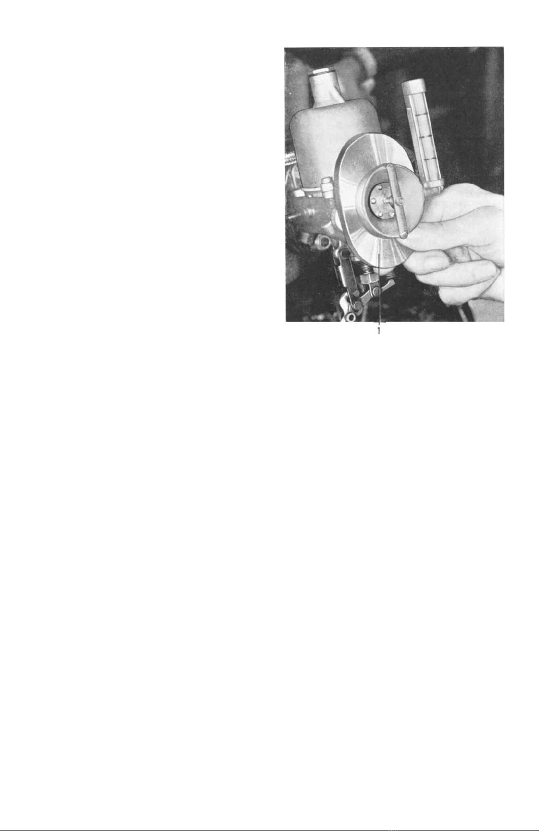
I
dling setting is carried out partly by means of the
screws (3 and 7, Fig. 4) on the throttle arms which
regulate engine speed, and partly by turning the
adjuster nuts on the jet heads (1, Fig. 19) whereby
the richness of the fuel mixture is altered. When
the nuts are screwed down, a richer fuel mixture
i
s obtained. If the nuts are screwed up the mixture
will
be leaner. The richness of the mixture is set
during idling to cover the whole speed range of
the engine.
When the correct idling speed has been obtained
and both carburetors have been adjusted to the
same level, they are then connected together.
I
ndividual settings should be carefully carried out
before the carburetors are connected together in
order to get the highest output from the engine.
1.
Run the engine until it is thoroughly warmed
up. If the jets have not been adjusted, a rough
adjustment can be first carried out by screwing
the adjuster nuts to their upper position and
then screwing them down again one complete
turn.
2.
Loosen one of the connections (9, Fig. 4) on
the shaft between the carburetors. Make sure
that the jets on both the carburetors are pres-
sing against the adjuster nuts and that the
screw (4) for rapid idling is not in contact with
the cam-shaped plate on each carburetor.
Fig. 20.
Measuring air flow for identical settings
on both carburetors.
1.
Vacuum-meter
3.
Adjust both throttles to the same position by
screwing out the throttle adjuster screws (3 and
7) and then screwing them in again until con-
tact
with the stop projections is just made.
Then screw down each screw exactly one turn.
Make sure that the throttles work freely and
i
ndependently.
4.
Start the engine. Check. that the throttles are
open to the same extent in both carburetors by
fitting
a special vacuum-meter to each air
cleaner contact surface. See Fig. 20. Adjust
the idling screws until the meter reading on
both carburetors is exactly the same.
5.
Adjust the jets by turning the adjuster nuts so
that the idling speed is as high as possible
with unchanged throttle opening. Adjust the
carburetors one at a time. First screw the
adjuster nuts (1, Fig. 19) upwards (leaner
mixture) until the engine runs unevenly and then
i
n the opposite direction until the engine runs
perfectly smoothly. If the idling speed is too
high it can be decreased by unscrewing the
i
dling screws on the throttle shaft levers. Then
check again as specified above that the air
i
ntake is equal on both carburetors.