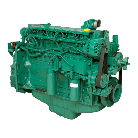
Volvo TAD734GE User manual

Users guide and maintenance
manual
V
VO
OL
LV
VO
O
D
Di
ie
es
se
el
l
e
en
ng
gi
in
ne
e
T
TA
AD
D7
73
34
4G
GE
E
E
EM
MS
S
2
2
7747302 (English03-2007)
33522069101_0_1


TAD734GE
(EMS 2)
OPERATOR’S MANUALp

Engine data
Engine designation ........................... Product number ....................................
Serial number .........................................................................................................
Clutch, type/nr. .......................................................................................................
Nearest Volvo Penta service location
Name .......................................................................... Telephone ....................
Address ...................................................................................................................
© 2007 AB VOLVO PENTA
Volvo reserves the right to make changes
Printed on environmentally friendly paper
Foreword
Volvo Penta industrial engines are relied upon throughout the world,
in both mobile and stationary applications, under some of the most
rigorous conditions imaginable. This is not by chance.
After more than 90 years of producing engines the name Volvo Penta
has come to symbolize reliability, technical ingenuity, first-class perfor-
mance and longevity. We believe that these characteristics are also
ultimately your requirements and expectations for new Volvo Penta
industrial engines.
To make certain that your expectations are matched, we ask that
you read carefully through the instruction book before starting
the engine.
Sincerely
AB VOLVO PENTA

Safety information ................................................. 2
Safety precautions for operation
and maintenance.................................................. 3
Introduction ........................................................... 6
Environmental care ............................................... 6
Running in ............................................................. 6
Fuel and oils ......................................................... 6
Maintenance and spare parts ................................ 6
Certified engines ................................................... 7
Warranty ................................................................ 7
Presentation .......................................................... 8
Technical description ............................................ 8
Identification numbers ........................................... 9
Component location ............................................. 10
Location of sensors.............................................. 11
EMS 2 ................................................................ 12
Instrument, EMS 2 ............................................... 13
DCU (Display Control Unit) ................................... 14
Starting the engine.............................................. 20
Before starting ................................................... 20
Start routine (DCU) ............................................. 21
Starting in extreme cold ..................................... 22
Never use start spray ......................................... 23
Starting with auxiliary batteries .......................... 23
Running ............................................................... 24
Check Gauges ................................................... 24
Fault indication................................................... 24
Operation at low load ......................................... 24
Stopping the engine ........................................... 25
Before stopping .................................................. 25
Stop ................................................................... 25
After stopping .................................................... 25
Auxiliary stop ...................................................... 25
Maintenance schedule ........................................ 26
Maintenance ........................................................ 28
Engine, general ................................................... 28
Lubrication system ............................................... 30
Cooling system ................................................... 33
Fuel system ........................................................ 38
Electrical system ................................................ 41
Shutdown ............................................................ 44
Preservation ........................................................ 44
Restoration ......................................................... 45
Troubleshooting.................................................. 46
Diagnostic function ............................................. 47
Fault notification ................................................. 47
Effect on the engine ............................................ 47
Operation ............................................................ 48
Reading fault codes ............................................ 48
Fault codes .......................................................... 50
Technical data ..................................................... 59
General ............................................................... 59
Lubrication system .............................................. 60
Fuel system ........................................................ 60
Cooling system ................................................... 61
Electrical system ................................................ 61
Table of contents

2
Safety information
Incorrect operation can lead to personal injury and damage to products or property. Therefore
read through the instruction book very carefully before you start the engine or do any mainte-
nance or servicework. If there is still something which is unclear or you are unsure of, please
contact your Volvo Penta dealer for assistance.
This symbol is used in the instruction book and on the product, to call your attention
to the fact that this is safety information. Always read such information very carefully.
Safety texts in the instruction book have the following order of priority:
WARNING! Warns for the risk of personal injury, major damage to product or property, or
serious malfunctions if the instruction is ignored.
IMPORTANT! Is used to call attention to things which could cause damage or malfunctions
to product or property.
NOTE! Used to draw your attention to important information that will facilitate the work or
operation in progress.
This symbol is used on our products in some cases and refers to important information in
the instruction book. Make sure that warning and information symbols on the engine are clearly
visible and legible. Replace symbols which have been damaged or painted over.
Read this chapter very carefully. It has to do with your safety. It describes how safety information is presented in
the instruction book and on the product. It also gives you an overview of the basic safety precautions for maintain-
ing the engine.
Check that you have received the correct operator’s manual before you read on. If not, please contact your
Volvo Penta dealer.

Safety information
3
Safety precautions for operation and maintenance
Daily Checks
Make a habit of always checking the engine compart-
ment before running (before the engine is started)
and after running (when the engine has been
stopped). This helps you to quickly discover whether
any leakage of fuel, coolant, oil or any other abnormal
event has happened, or is about to happen.
Fuel Filling
There is always a risk of fire and explosion when refu-
eling. Smoking is forbidden, and the engine must be
stopped.
Never over-fill the tank. Close the tank cap securely.
Only use the fuel recommended in the instruction
book. The wrong grade of fuel can cause malfunctions
or stop the engine. In a diesel engine, it can also
cause the injection pump to bind and the engine to
over-rev, entailing a strong risk of personal injury and
machinery damage.
Carbon Monoxide Poisoning
Only start the engine in a well-ventilated area. When
running in a confined space, exhaust fumes and
crankcase gases must be led away.
Operation
The engine must not be operated in environments
which contain explosive media since none of the elec-
trical and mechanical components are spark proof.
Approaching a running engine is a safetyrisk. Hair, fin-
gers, loose clothes, or dropped tools can catch on ro-
tating components and cause severe injury.
When engines are supplied without touch guards, all
rotating components and hot surfaces must be pro-
tected after installation in their application, if neces-
sary for personal safety.
Ignition Lock
If the instrument panel does not have a key switch,
the engine compartment must be lockable, to prevent
unauthorized persons from starting the engine. Alter-
natively, a lockable main switch can be used.
Maintance and Service
Proficiency
The instruction book contains directions on how to
carry out the most common service and maintenance
tasks safely and correctly. Read them carefully before
starting work.
Literature for more major tasks is available from your
Volvo Penta dealer.
Never do a job if you are not entirely sure about how
to do it. Please contact your Volvo Penta dealer and
ask for assistance instead.
Stop the Engine
Stop the engine before opening or removing the en-
gine hatch/hood. Maintenance and service should be
done with the engine stopped, unless otherwise speci-
fied.
Prevent the engine from being started by pulling out
the starter key and cutting the current with the main
switch. Lock them in the off position. Fix a notice by
the operator’s station to say that work is in progress.
Working with, or approaching a running engine is a
safety risk. Hair, fingers, loose clothes, or dropped
tools can catch on rotating components and cause se-
vere injury. Volvo Penta recommends that all service
work which requires the engine to be running should
be done by an authorized Volvo Penta workshop.

Safety information
4
Removing the Engine
When removing the engine the lifting rings mounted on
the engine should be used. Always check that the lift-
ing devices are in good condition and that they have
the correct capacity for the lift (engine weight together
with auxiliaries, if fitted). The engine should be raised
with an adjustable lifting boom for safe handling. All
chains or cables should be parallel to each other and
should be as square as possible to the top of the en-
gine. Note that auxiliary equipment installed on the en-
gine may change its center of gravity. Special lifting
devices may then be needed to obtain a correct bal-
ance for safe handling. Never carry out work on an en-
gine that is only suspended in a hoist.
Before Starting
Re-install all guards which have been removed during
service work, before re-starting the engine. Make sure
that there are no tools or other objects left behind on
the engine.
Never start a turbocharged engine without the air filter
in place. The rotating compressor turbine in the turbo-
charger can cause severe injury. There is also a risk
that foreign bodies could be sucked in and cause ma-
chinery damage.
Fire and Explosion
Fuel and Lubricating Oil
All fuel, most lubricants and many chemicals are
flammable. Always read and follow the directions on
the packages.
Work on the fuel system must be done with the en-
gine cold. Fuel leakages and spills on hot surfaces or
electrical components can cause fires.
Store oil and fuel-soaked rags and other flammable
material in such a way that there is no danger of them
causing fire. In certain circumstances oil-soaked rags
can spontaneously ignite.
Never smoke when filling fuel, lubricating oil or when
in the vicinity of fueling stations or the engine bay.
Non-original Spare Parts
Components in fuel systems and electrical systems
on Volvo Penta engines are designed and manufac-
tured to minimize the risk of explosions and fire, in ac-
cordance with applicable legal requirements.
The use of non-original spare parts can cause an ex-
plosion or fire.
Batteries
Batteries contain and give off oxyhydrogen, especially
when charged. This gas is very flammable and highly
explosive.
Smoking, naked flames or sparks must never occur in
the vicinity of batteries or the battery compartment.
Incorrect connection of a battery cable or start cable
can cause a spark which can in turn be sufficient to
cause the battery to explode.
Start Spray
Never use start spray or similar preparations as a
start aid on engines with air pre-heating (glow plugs/
starting heater). They may cause an explosion in the
inlet manifold. Danger of personal injury.
Safety precautions for operation and maintenance (contd.)

Safety information
5
Hot Surfaces and Fluids
A hot engine always presents the risk of burns. Be on
your guard against hot surfaces: the exhaust mani-
fold, turbocharger, oil pan, charge air pipe, starting
heater, hot coolant and hot lubricating oil in pipes,
hoses etc.
Chemicals
Most chemicals, such as glycol, rust preventer, con-
servation oils, degreasers etc. are hazardous. Always
read and follow the directions on the packages.
Certain chemicals such as preservative oils are flam-
mable and also dangerous when inhaled. Ensure good
ventilation and use a protective mask when spraying.
Always read and follow the directions on the packages.
Keep chemicals and other hazardous materials out of
the reach of children. Hand in surplus or used chemi-
cals to a recycling station for disposal.
Lubrication System
Hot oil can cause burns. Avoid skin contact with hot
oil. Make sure that the oil system is de-pressurized
before starting work. Never start or run the engine with
the oil filler cap removed, because of the risk of oil
ejection.
Cooling System
Avoid opening the coolant filling cap when the engine
is hot. Steam or hot coolant can spray out and cause
burns.
Nevertheless, if the filler cap, coolant hose etc., has
to be opened or removed when the engine is hot, undo
the filler cap slowly and carefully, to release the pres-
sure before removing the filler cap completely and
starting work. Note that the coolant can still be hot
and cause burns.
Fuel System
Always protect your hands when searching for leaks.
Fluids which leak under pressure can force their way
into body tissue and cause severe injury. There is a
risk of blood poisoning (septicemia).
Always cover the alternator if it is located beneath the
fuel filters. Fuel spillage can damage the alternator.
Electrical system
Cut the Current
Before any work is done on the electrical system, the
engine must be stopped and the current cut by switch-
ing off the main switch(es). External current supply for
engine heaters, battery chargers or other auxiliary
equipment connected to the engine must be discon-
nected.
Batteries
Batteries contain a highly corrosive electrolyte. Pro-
tect your eyes, skin and clothes when handling or
charging batteries. Always use protective goggles and
gloves.
If acid comes into contact with your skin, wash with
soap and plenty of water. If you get battery acid in
your eyes, flush at once with lots of cold water, and
seek medical assistance immediately.
Arc Welding
Remove the positive and negative cables from the
batteries. Then disconnect all cables connected to the
alternator.
Always connect the welder earth clamp to the compo-
nent to be welded, and as close as possible to the
weld site. The clamp must never be connected to the
engine or in such a way that current can pass through
a bearing.
When welding is completed: Always connect the al-
ternator cables before the battery cables are re-at-
tached.

6
Introduction
This instruction book has been prepared to give you the greatest possible benefit from your Volvo Penta industrial
engine. It contains the information you need to be able to operate and maintain the engine in a safe and propper
manner. Read the instruction book carefully and learn how to operate the engine, controls and other equipment in
a safe manner before you start the engine.
Environmental care
All of us want to live in a clean, healthy environment,
where we can breathe clean air, see healthy trees,
have clean water in lakes and seas, and be able to
enjoy sunshine without fearing for our health. Unfortu-
nately, this cannot be taken for granted these days; it
is something all of us must work toward.
As an engine manufacturer, Volvo Penta has particular
responsibility and for this reason, environmental care is
an obvious foundation of our product development. Vol-
vo Penta currently has a broad range of engines where
great progress has been made in the reduction of em-
misions, fuel-consumption and engine noise etc.
We hope that you will take care to maintain these
qualities. Always follow the directions in the instruc-
tion book regarding fuel grades, operation and mainte-
nance, to avoid unnecessary environmental impact.
Please contact your Volvo Penta dealer if you notice
any changes such as increased fuel consumption or
increased exhaust smoke.
Always remember to hand in hazardous waste such
as drained oil, coolant, old batteries etc. for disposal
at a recycling facility.
Through our common efforts, we can together make a
valuable contribution to the environment.
Running in
The engine must be “run in” during its first 10
running hours, in accordance with the following:
Use the engine in normal operation. Full load should
only be applied for short periods. Never run the engine
at constant revolutions for prolonged periods during
running in.
Higher oil consumption is normal during the first 100-
200 hours of operation. For this reason, check the oil
level more frequently than the normal reccomendation.
When an disengageable clutch is installed, this should
be checked more carefully during the first days. Ad-
justments may need to be done to compensate bed-
ding-in of the friction plates.
Fuel and Oils
Only use the grades of fuels and oils recommended in
the instruction book (refer to the “Maintenance” chapter
under the fuel and lubrication system headings). Other
grades of fuel and oils can cause malfunctions, increased
fuel consumption and over time even shorten the life of
the engine.
Always change the oil, oil filter and fuel filter according
to the prescribed intervals.
Maintenance and Spare Parts
Volvo Penta engines are designed for maximum reli-
ability and long life. They are built to withstand a de-
manding environment, but also to have the smallest
possible environmental impact. Regular maintenance
and the use of Volvo Penta original spare parts will
ensure these qualities are retained.
Volvo Penta has a world-wide network of authorized
dealers. They are Volvo Penta product specialists,
and have the accessories, original spares, test equip-
ment and special tools necessary for high quality ser-
vice and repair work.
Always comply with the maintenance schedule in
the instruction book, and remember to note the
engine/transmission identification number when
you order service and spare parts.
IMPORTANT! This instruction book describes the engine and equipment as offered for sale by Volvo Penta.
Variations in appearance and function of the controls and instruments may occur in certain variants. In these
cases, refer to the operator’s manual for the relevant application.
Introduction
7
Certified Engines
If you own an emission certified engine, which is
used in an area where exhaust emissions are regu-
lated by law, it is important to be aware of the fol-
lowing:
Certification means that an engine type has been
checked and approved by the relevant authority. The
engine manufacturer guarantees that all engines made
of the same type are equivalent to the certified engine.
This places special demands on the maintenance
and service you provide your engine; accordingly:
•Maintenance and service intervals recommended
by Volvo Penta must be complied with.
•Only Volvo Penta original spare parts may be
used.
•Service to injection pumps, pump settings and in-
jectors must always be done by an authorized
Volvo Penta workshop.
•The engine must not be converted or modified, ex-
cept with accessories and service kits which
Volvo Penta has developed for the engine.
•No installation changes to the exhaust pipe and
engine air inlet ducts may be made.
•Any seals on the engine may not be broken by un-
authorized persons.
Otherwise the general instructions in the Operator’s
Manual regarding operation, maintenance and service
apply.
IMPORTANT! Neglected or inferior maintenance/
service or the use of non-original spare parts, will
result in AB Volvo Penta no longer accepting
responsibity for engine conformity with the certi-
fied model.
Damage, injury and/or costs which arise from
this will not be compensated by Volvo Penta.
Warranty
Your new Volvo Penta industrial engine is covered by a limited warranty, according to the terms and
conditions set out in the Warranty and Service book.
Please note that AB Volvo Penta’s liability is limited to that which is stated in the Warranty and Service
book. Read it carefully, as soon as possible after delivery. It contains important information about,
among other things, warranty cards, sevice intervals and maintenance which, as the owner, is your re-
sponsibility to know, check and execute. Otherwise AB Volvo Penta may fully or partly refuse to honor
its warranty undertakings.
Please contact your Volvo Penta dealer if you have not received a Warranty and Service book, or
a customer copy of the warranty card.

8
Presentation
TAD734GE is a direct injection, straight, 6-cylinder engine.
The engine is equipped with a “common rail” fuel injection system, IEGR (Internal Exhaust Gas Recirculation),
electronically-controlled fuel management (EMS 2), turbocharger, thermostatically-controlled cooling systems and
electronic speed control.
Technical Description
Engine and Cylinder Block
– The cylinder block and cylinder head are manufac-
tured of alloyed cast iron
– Seven bearing induction-hardened crankshaft
– Replaceable wet cylinder liners
– Cast aluminum pistons with oil cooling
– Three piston rings, with a “keystone” type top ring
– Induction-hardened overhead camshaft with valve
lifters and push rods.
– Four valves per cylinder
– Replaceable valve seats and valve guides
Control Unit
– Microprocessor-based fuel supply control unit,
EMS 2
Fuel System
– Common rail fuel injection
– Gearwheel fuel feed pump, camshaft driven
– EMS 2 (Engine Management System). See sepa-
rate description.
Lubrication System
– Water oil cooler
– Crankshaft driven lubrication oil pump
– Full flow filter with bypass
Turbocharging System
– Turbo compressor
Cooling System
– Radiator with expansion tank
– Air-cooled charge air cooler
Electrical system
– 24 V

Presentation
9
Identification Numbers
1. Engine model
2. Engine specification number
3. Engine series number (10 digits)
4. Engine power, peak, without fan
5. Engine rpm
6. Engine code (linked to EPA/EU Tier III approval)
7. Rated power, standard
(peak power according to Tier III)
8. Air temperature in °C (°F), in accordance
with ISO 3046
9. Altitude above mean sea level, in accordance
with ISO 3046
10. EU Tier III approval number
Location of Engine Plates
The engines are supplied with two engine plates, of which one is situated on the right side of the engine block and
the other on top of the valve cover.
Engine Plate

Presentation
10
Component Locations, TAD734GE
1. Crankcase ventilation, (sealed crank-
case ventilation optional)
2. Oil Filler
3. Fuel filter
4. Common Rail unit, with safety valve
and rail pressure sensor
5. Oil filter
6. Lifting eyes, (2 pcs)
7. Inlet, after charge-air cooler
8. Coolant outlet, from thermostat housing
9. Fan hub
10. Alternator
11. Drive belt
12. Damper and belt pulley
13. Oil pan
14. Tensioner pulley
15. Coolant inlet, to engine
16. Drain plug, oil pan
17. Oil Cooler
18. Coolant pump
19. Outlet, engine heater (option)
20. Dipstick
21. High pressure pumps
22. Air inlet pipe
23. Valve cover
24 Indicator, air filter
25. Fuel pump
26. Flywheel housing
27. Starter motor guard
28. Charge air, to cooler
29. Oil pipe, from turbo
30. Turbo
31. Relay
32. Exhaust manifold

Presentation
11
Location of sensors
1. Proportional solenoid valve, high pres-
sure pump – fuel (MPROP)
2. Coolant temperature
3. Water in fuel, (mounted on fuel pre-filter).
4. Charge air pressure and temperature
5. Pre-heating, inlet air
6. Fuel pressure in distributor manifold (Rail)
7. Fuel pressure
8. Oil pressure sensor
9. Relay
10. Rpm sensor, flywheel
11. Rpm sensor, camshaft
NOTE! Positions may differ, depending on the engine model.

Presentation
12
EMS 2
EMS 2 (Engine Management System) is an electronic system with CAN communication (Controller Area Network)
for diesel engine control. The system has been developed by Volvo and includes fuel control and a diagnostic
function.
Fuel Management
The engine fuel requirement is analyzed up to 100
times per second. The amount of fuel injected into the
engine and the injection timing are fully electronically
controlled, via fuel valves on the unit injectors.
This means that the engine always receives the cor-
rect amount of fuel in all operating conditions, which
provides lower fuel consumption and minimal exhaust
emissions etc.
Diagnostic Function
The task of the diagnostic function is to discover and
localize any malfunctions in the EMS 2 system, to
protect the engine and to inform about any problems
that occur.
If a malfunction is detected it is denoted by warning
lamps, a flashing diagnostic lamp or in text on the in-
strument panel, depending on the equipment used. If
a flashing or text fault code is generated, use the
code for guidance when trouble shooting. Fault codes
can also be deciphered by Volvo’s VODIA tool at au-
thorized Volvo Penta workshops.
If there is a serious malfunction, the engine will be
shut down altogether, or the control unit will reduce
available power (depending on the application). Once
again, a fault code will be generated for guidance in
trouble shooting.
Summary
The system comprises, among other things, of a con-
trol unit, sensors and injectors. The sensors send in-
put signals to the control unit, which in turn controls
the injectors.
The information from the sensors give exact data
about prevailing operating conditions and allows the
processor in the control module to calculate correct
injection amount, injection timing and check engine
health.
Input signals
The control unit receives input signals about engine
operating conditions from the following components:
– coolant temperature sensor
– charge air pressure and temperature sensor
– rpm sensor, camshaft
– rpm sensor, flywheel
– coolant level sensor
– oil pressure sensor
– fuel pressure sensor
– water in fuel indicator
– fuel pressure in distributor manifold
Output signals
Based on the input signals the control module controls
the following components:
– unit injectors
– starter motor
– main relay
– pre-heating relay
– FCU (Fuel Control Unit)

Presentation
13
Instrument, EMS 2
NOTE! All instruments are fittings.
CIU – Control Interface Unit
The CIU is the “translator” between the EMS 2 engine
control unit and the customer’s own control panel. The
CIU has two serial communication links, one fast and
one slow.
The fast one is a so-called CAN link. All data related
to instruments, indication lamps, connectors and po-
tentiometers is controlled by this link.
The slow link manages diagnostic information for
flashing codes etc.
Easy Link instrument
(only in conjunction with CIU or DCU)
The following “Easy Link” instruments are available:
– Engine rpm/hour meter (fault codes are also dis-
played on the tachometer display when the diag-
nostic button is pressed)
– Coolant temperature
– Oil pressure
– Turbo pressure
– Battery voltage
– Alarm panel
DU - Display Unit
The DU is an instrument panel which shows engine
working values graphically on an LCD screen. It con-
sists of an computerised unit for permanent installa-
tion in a control panel.
The DU is connected between the engine control unit
and the CIU or DCU.
Monitoring
– Engine rpm, charge pressure, charge temperature,
coolant temperature, oil pressure, oil temperature,
fuel pressure, engine hours, battery voltage, mo-
mentary fuel consumption and average fuel con-
sumption (trip fuel)
Diagnostics
– Shows active fault codes in text

14
DCU (Display Control Unit)
The DCU (Diesel Control System) control panel is available as an accessory for the EMS (Engine Management
System) electronic control system. The DCU is a digital instrument panel which communicates with the engine
control unit. The DCU has a number of functions such as engine control, engine monitoring, diagnostics and pa-
rameter setting.
The menus in the DCU system can be used to check, and in some cases to set, a number of different functions
in the EMS system.
NOTE! The menus and illustrations shown here are from the English version. The language can be changed, how-
ever; refer to the “Setup” menu.
1. LED display
2. START. Starts the engine
3. SPEED -. Reduces engine rpm
4. SPEED +. Increases engine rpm
5. STOP. Stops the engine
6. ON/OFF. Starts and stops the system
7. Scrolls down in menus
8. SEL. Selects from menus
9. Scrolls up in menus
10. ESC. Return to previous menu selection
12345
7
8910
6
Start
When the DCU panel is started, the “Engine Data” menu is displayed; press “ESC” to come to the main menu.

15
Menus
There are several sub-menus under each main menu.
There is not always space for all the menu choices on
the display. To scroll through the menus, use the “7”
and “9” buttons on the display. Press the “SEL” button
“8” to make a selection. See illustration on the previ-
ous page.
NOTE! The “Setup” menu can be used to select the
language that you want to use on the display.
Main menu
nEngine data, current engine data
nPreheat, manual activation of preheating
OBS! Must be activated when the temperature is
below 0°.
nGovernor mode, activates droop
nDiagnostics, shows fault codes in text
nTrip reset, restores trip data
nSetup, parameter setting
nInformation, shows the data for the applicable
hardware, software, data set and engine identifica-
tion of the engine and DCU
Engine data
shows relevant engine data.
• Engine rpm, can be controlled with the “SPEED +”
and “SPEED -” buttons (rpm)
• Charge pressure (kPa)
• Coolant temperature (°C)
• Charge air temperature (°C)
• Oil pressure (kPa)
•Oil temperature (value not shown – sender missing)
• Engine hours (h)
• Battery voltage (V)
• Fuel consumption (l/h)
• Momentary fuel consumption (trip fuel) (l)

16
Preheat
manual activation of preheating. When activated, the
EMS system senses at start if preheating is neces-
sary. For automatic preheating, refer to “Setup”/“Pre-
heat on ignition” menu.
NOTE! Must be activated when the temperature is be-
low 0°.
The preheating time is adjusted to suit the engine
temperature, and can last for up to 50 seconds both
before and after starting. Also refer to “Starting proce-
dure, EMS 2”.
• Press “SEL”, the text “Preheat requested” is dis-
played.
• The display automatically returns to the “Engine
Data” menu.
Governor mode
activates/deactivates droop. To set the droop level,
refer to the “Setup”/“Governor gradient” or “Govenor
droop”.
• Select “Isochronous mode” or “Droop mode” with
the SEL button.
Diagnostics
shows the error list containing the 10 latest active and
inactive faults. The fault codes are shown as text on
the display.
• Scroll through the error list with the arrow keys.
Trip reset
resets trip data e.g. fuel consumption.
• Press the SEL button to reset trip data.
Table of contents
Other Volvo Engine manuals

Volvo
Volvo EPA2007 D13F User manual

Volvo
Volvo TAD650VE Instruction manual

Volvo
Volvo MB10A Instruction manual

Volvo
Volvo B 17 User manual

Volvo
Volvo B5254T3 User manual

Volvo
Volvo D5 series User manual

Volvo
Volvo MD2010 Instruction manual

Volvo
Volvo TAD1240GE User manual

Volvo
Volvo B 17 User manual

Volvo
Volvo D13F User manual
Popular Engine manuals by other brands

Quectel
Quectel L10 Hardware design

Cleco
Cleco A8R309M Instruction manual and parts listing

Ingersoll-Rand
Ingersoll-Rand XP825WCU Operating, maintenance and parts manual

SEW-Eurodrive
SEW-Eurodrive DR Series Addendum to the operating instructions

Thumpstar
Thumpstar KXD owner's manual

B&S
B&S 2967 00 operating instructions