manuals.online logo
Brands
  1. Home
  2. •
  3. Brands
  4. •
  5. Von Duprin
  6. •
  7. Door Lock
  8. •
  9. Von Duprin M996L Series User manual

Von Duprin M996L Series User manual

*941369-00*
941369-00
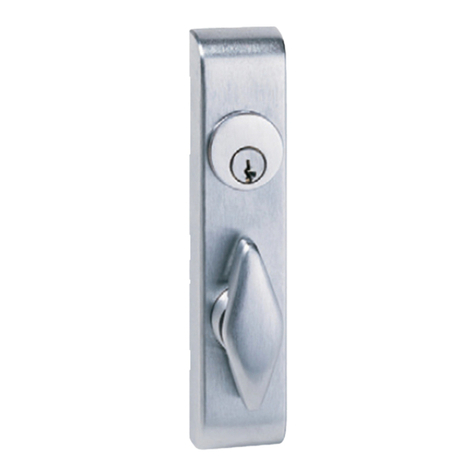
Motorized Locking Trim
M996L Series
Installation Instructions
M996L
for Rim/Vertical
M996L
for Mortise
Parts Included
Tools Needed
⁵⁄₁₆" Nut driver
#2 Phillips
1Retrofit / replace operation if necessary. (See M996L Series Retrofit, 941389-00)
Change function (Fail Safe or Fail Secure) if necessary.
2
Fig. 2-1
Unit locks when electric
power is applied and
unlocks when power is
removed
FS (fail safe)
factory setting
Unit unlocks when
electric power is applied
and locks when power
is removed
FSE (fail secure)
2.1. To change function, use the tip of a small screwdriver to CAREFULLY move the switch to the desired position. The
switch is factory set to fail safe (FS). Moving the switch changes the function to fail secure (FSE). After changing FS/FSE
switch position, power cycle the unit two or more times before installation. See Figure 2-1.
FS
FSE
FS
FSE
CAUTION
!
Product is shipped in Fail Safe (FS) configuration. Fail Safe configuration is required by code in some applications (typically fire
stairwells). Consult building codes before converting to Fail Secure (FSE) configuration. See page 8 for FS/FSE function information.
M996 Motorized Module
Page 2 of 8
Connect trim plug to cable plug (See Figure 12-1).
3
Page 3 of 8
Check exit device NL drive screw.
4
For mortise device applications see Figure 4-3.
Installation of the NL drive screw sets the exit device for NL (night latch) operation, which is
required for use with the E996L rim/vertical trim.
Fig. 4-1
NL drive
screw
Center case cam
Make sure cup on center case
cam points toward latch bolt
LHR
RHR
NL drive
screw
Center case cam
Make sure cup on center case
cam points toward latch bolt
Fig. 4-2
NOTE
!
Fig. 4-3
For rim/vertical device applications, make sure the NL drive screw is installed in the exit device center
case cam with the exit device lock slide in the up position. See figure 4-1 for LHR applications and
Figure 4-2 for RHR applications. (Device is shipped from factory with NL drive screw installed.)
Rim/Vertical
Mortise
For mortise device applications, NL screw
located on side of 7500 mortise lock
remains as shipped for NL operation. As
shipped position is when NL screw is
turned out counterclockwise. For any
questions, contact technical support.
If the exit device lock slide is not in the up position: Remove NL drive screw
and use a Phillips head screwdriver to rotate the exit device center case cam
to move the lock slide into the up position. Then reinstall NL drive screw.
Make sure latch
bolt is extended
Make sure lock
slide in up
position
Make sure latch
bolt is extended
Make sure lock
slide in up
position
Page4of8
98/9947
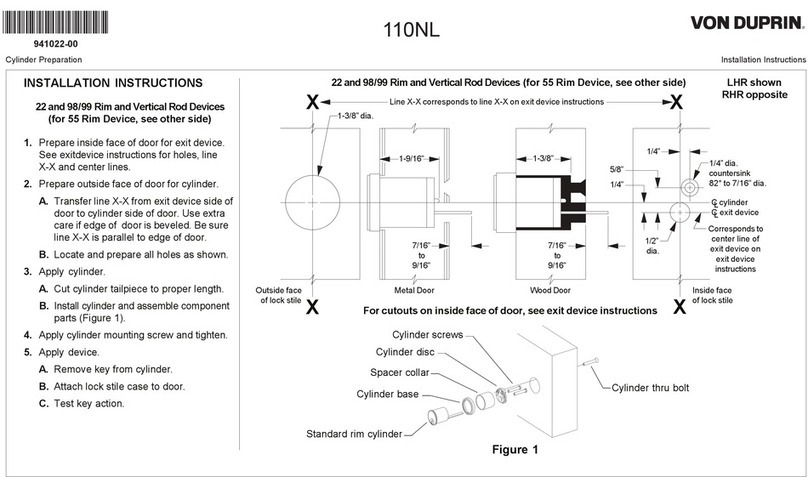
5.1. Prepareexit deviceside of door usinginstructionsand template providedwithexit device.
5.2. Prepare trim side of door using dimensions on frontsideofinstruction sheet921003/921006.
Prepare holesand cut-outsondoor.
5
C
L
RHR LHR
C
L
98/99 Rim, 98/9927, & 98/9975
3/4”
3/4”
2-3/4”
2-3/4”
Fig.5-1
98/99 Rim, 98/9927, & 98/9975
3/4”
Locate wire access slots.
6
Fig.6-1
98/9947
98/99Rim,98/9927, &98/9975
2-3/4” 3/4”
2-3/4”
RHR
wire access
LHR
wire access
RHR
wire access
LHR
wire access
Note: Each center case has 4 slots that can be used for wire access.
Some slots may be obstructed by optional equipment.
Drill and deburr 3/8”
dia. hole here thru
exit device side of
door for wiring
Drill and deburr 3/8”
dia. hole here thru
exit device side of
door for wiring
Drill and deburr 3/8”
dia. hole here thru
exit device side of
door for wiring
Page 5of8
RouteE996L cable through 98/99 series exit device.
7
Fig.7-3
7.2. Slidemechanism case offbaseplateassembly (Figure7-2).
7.4.
7.5. Slide mechanismcase backondevice. Align two plasticpushbar guides while installing
mechanismcase(Figure7-2).
7.6. Slide mechanism case back against center case. Leave 4-6” of cable protruding from
center case end of device (Figure 7-4).
7.7. Reinstall twomechanismcase screws (Figure7-1).
7.1. Remove twomechanism case screws (Figure7-1).
Fig.7-4
CAUTION
!
Be careful not to pinch cablewhen sliding
mechanism case back against center case.
7.3. RouteE996L cablethrough center case slots as shown(Figure 7-1).Cableplugshould be on
door side of center case as shown(Figure7-1).
Fig.7-1
RHR Shown
(LHR Opposite)
98/99Rim,98/9927, &98/997598/9947
RHR Shown
(LHR Opposite)
Fig.7-2
Mechanismcase
Pushbar guides
Base plate
CAUTION
!
Ensure wire will not
interfere with moving
components.
Place E996L cable in groove on bottom of baseplate (Figure 7-3).
Optional:Use electrical tape to hold cable in place.
Cable
plug
Cable
Mechanism
case screws
Cable
plug
Cable
Mechanism
case screws
Leave 4-6” of
cable protruding
(99 Rim shown)
Hold cable in groove
(or use electrical tape)
Page 6 of 8
Install end cap bracket and route wiring through power transfer.
9.1. Install mounting bracket into mechanism case and install two screws loosely (Figure 9-1).
9.2. Slide cable into 5/8” wiring access hole under mounting bracket. (Figure 9-1).
9.3. Route cable through door and attach wiring to power transfer. (Figure 9-2).
Note: EPT recommended for new construction; electric hinge or door loop recommended for retrofit.
Locate end cap bracket on door and prepare second wiring access hole.
8
5/16”
C
L
center
case
E996L Trim
1-1/2” Minimum clearance
(with end cap removed) if device is
too long for door, see “Cut Device”
on device instructions
Mounting
bracket flush
8.1. Temporarily attach trim and device to door with 4 screws (Figure 8-1).
8.2. Slide mounting bracket in end of mechanism case and level device, then mark two mounting
holes on door through bracket holes (Figure 8-2).
8.3. Mark and prepare two holes for mounting bracket screws (Figure 8-3).
8.4. Mark, drill, and deburr 5/8” hole for wiring access (Figure 8-4).
Fig. 8-1Fig. 8-2
Fig. 8-4Fig. 8-3
Two holes (see “Preparation Chart” in exit
device instructions for drill and tap sizes)
Level device
Mechanism
case
9
5/8” dia. drill, device side of door only.
Deburr after drilling.
Fig. 9-1 Fig. 9-2
Power transfer
(Von Duprin
EPT2 shown)
Mounting
bracket
Cable in hole
Page 7 of 8
Attach center case to door.
10
10.1.Support hinge side of device in mounting bracket.
10.2.If trim has been temporarily installed, remove 4 screws in center case and remove trim.
10.3. Pull center case away from door and route E996L cable plug through wire access hole in
door (Figure 10-1).
10.4.For 98/99 Rim, 98/9927, and 98/9975 secure center case to door using two support
screws (Figure 10-1) or by some other temporary means (use clamps, have a helper hold the
device, etc.).
Fig. 10-1
Two support screws Two support screws
Cable plug Cable plug
Install trim on door.
12
12.1.Connect trim plug and cable plug (Figure 12-1).
12.2.Route wires into corner of the cutout near post. Push the wires down into the door to
ensure they do not contact the slider (Figure 12-1).
Note:For 98/9947 device, hold trim in door and lift center case away from the door surface while
rods and trim remain in place. Route wiring as shown in Figure 12-2. Verify that the wires do
not get wrapped around or pinched in rods or slider, then align center case and attach rods.
12.3.Attach trim to door using four screws through device center case (Figure 12-3).
12.4. Install center case cover (see device instructions if necessary).
Fig. 12-1
Plugs
For vertical or mortise devices, install vertical rods or mortise lock in door.
11
RHRLHR
Fig. 12-3
Trim
Fig. 12-2
Rods and slider
(no interference)
© Allegion 2020
Printed in U.S.A.
941369-00 Rev. 03/20-a
Customer Service
1-877-671-7011 www.allegion.com/us
Test trim function.
15
For FS (Fail Safe) trim (factory default):
A. With the power applied, the trim will move to the locked position. The trim’s lever must be allowed to
be in the resting or home position for the trim to lock.
B. Removing power will cause the trim to move to the unlocked position. The trim’s lever must be
allowed to be in the resting or home position for the trim to unlock. Once the trim unlocks, the lever
may be turned.
C. When key cylinder is present on trim, with power engaged, check to ensure that the key override
feature (night latch) functions properly. Inserting and turning key will temporarily unlock door while trim
lever remains rigid. Door locks when key is removed.
For FSE (Fail Secure):
A. With the power applied, the trim will move to the unlocked position. The trim’s lever must be allowed
to be in the resting or home position for the trim to unlock. Once the trim unlocks, the lever may be
turned.
B. Removing power will cause the trim to move to the locked position. The trim’s lever must be allowed
to be in the resting or home position for the trim to lock.
C. When key cylinder is present on trim, with power disengaged, check to ensure that the key override
feature (night latch) functions properly. Inserting and turning key will temporarily unlock door while trim
lever remains rigid. Door locks when key is removed.
Troubleshooting.
16
With the trim plugged into cable, the electronic control can be verified using indicators located on the backside
of the trim. This is only possible when trim is not mounted on the door.
GREEN LED
Indicates the Power status
ON= Controller is powered by the control signal.
OFF= Controller is not powered by the control signal (if power was recently disconnected, can
take up to one minute for LED to turn off).
RED LED
Flashes ON= Mechanism is moving to the unlocked or locked position.
The locked/unlocked operation is dependent on the Fail-Safe or Fail-Secure Switch Position.
13 Power control
requirements.
The two wires are non-polarized 12/24 VDC input. One wire connects directly to a
12/24 VDC power source (power supply) and the other wire connects to a control
device (card reader, key pad, push button, dry contact, etc.) and then to the power
supply. See diagram below.
Fig. 13-1
+
Power wire runs through
exit device body
Power transfer (EPT2 shown)
M996L
trim
12/24 VDC
output
Power Supply
PS902
A 12/24 VDC
1A minimum
power signal
A 1-second minimum
on-time control pulse
A 1-second minimum
off-time control pulse
Basic wiring information.
Control device
NO contacts for FS
NC contacts for FSE
14
This manual suits for next models

1

Other Von Duprin Door Lock manuals

Von Duprin 940L User manual

Von Duprin

Von Duprin 940L User manual

Von Duprin StrikeForce 6210 User manual

Von Duprin

Von Duprin StrikeForce 6210 User manual

Von Duprin 377-T User manual

Von Duprin

Von Duprin 377-T User manual

Von Duprin 6212WF User manual

Von Duprin

Von Duprin 6212WF User manual

Von Duprin 33 User manual

Von Duprin

Von Duprin 33 User manual

Von Duprin 6300 User manual

Von Duprin

Von Duprin 6300 User manual

Von Duprin 990 series User manual

Von Duprin

Von Duprin 990 series User manual

Von Duprin 98 Series User manual

Von Duprin

Von Duprin 98 Series User manual

Von Duprin 98 User manual

Von Duprin

Von Duprin 98 User manual

Von Duprin 5100 User manual

Von Duprin

Von Duprin 5100 User manual

Von Duprin 6226 User manual

Von Duprin

Von Duprin 6226 User manual

Von Duprin CX33A User manual

Von Duprin

Von Duprin CX33A User manual

Von Duprin 6111 User manual

Von Duprin

Von Duprin 6111 User manual

Von Duprin 110NL User manual

Von Duprin

Von Duprin 110NL User manual

Von Duprin StrikeForce 6210 User manual

Von Duprin

Von Duprin StrikeForce 6210 User manual

Von Duprin 230L-BE User manual

Von Duprin

Von Duprin 230L-BE User manual

Von Duprin Strike Force 6211 User manual

Von Duprin

Von Duprin Strike Force 6211 User manual

Von Duprin 6225 User manual

Von Duprin

Von Duprin 6225 User manual

Von Duprin 375-L User manual

Von Duprin

Von Duprin 375-L User manual

Von Duprin StrikeForce 6211WF User manual

Von Duprin

Von Duprin StrikeForce 6211WF User manual

Von Duprin 6211AL User manual

Von Duprin

Von Duprin 6211AL User manual

Von Duprin 33 User manual

Von Duprin

Von Duprin 33 User manual

Von Duprin 22 Series User manual

Von Duprin

Von Duprin 22 Series User manual

Von Duprin 99 User manual

Von Duprin

Von Duprin 99 User manual

Popular Door Lock manuals by other brands

Simons Voss PegaSys Door Handle 4.1 Reader on both sides quick guide

Simons Voss

Simons Voss PegaSys Door Handle 4.1 Reader on both sides quick guide

Linear T100 Series installation instructions

Linear

Linear T100 Series installation instructions

Schlage BE469 user guide

Schlage

Schlage BE469 user guide

Lockly SECURE PRO installation guide

Lockly

Lockly SECURE PRO installation guide

Simpled CF-YC user manual

Simpled

Simpled CF-YC user manual

Kwikset Signature Series Austin 720AUL 11P CP Quick installation guide

Kwikset

Kwikset Signature Series Austin 720AUL 11P CP Quick installation guide

Trident MANTA PRO user manual

Trident

Trident MANTA PRO user manual

Philips EasyKey 9000 Series user manual

Philips

Philips EasyKey 9000 Series user manual

Assa Abloy Sargent AL-PE80 Series installation instructions

Assa Abloy

Assa Abloy Sargent AL-PE80 Series installation instructions

BANKSTON Edition Office Pull 01 installation instructions

BANKSTON

BANKSTON Edition Office Pull 01 installation instructions

Vicenza Designs DHPA8000 Instructions for installation

Vicenza Designs

Vicenza Designs DHPA8000 Instructions for installation

SCOOP Pullbloc 3.1 Assembly instruction

SCOOP

SCOOP Pullbloc 3.1 Assembly instruction

Assa Abloy Aperio C100 V3 Installation and mounting instructions

Assa Abloy

Assa Abloy Aperio C100 V3 Installation and mounting instructions

Salto Comfort E1CD0x00fft installation guide

Salto

Salto Comfort E1CD0x00fft installation guide

Assa Abloy Arrow Revolution U4A-YRHCPZW0 Installation and programming instructions

Assa Abloy

Assa Abloy Arrow Revolution U4A-YRHCPZW0 Installation and programming instructions

Dorma RTS Series quick start guide

Dorma

Dorma RTS Series quick start guide

prudhomme TS75 instructions

prudhomme

prudhomme TS75 instructions

SDC FS23M Series installation instructions

SDC

SDC FS23M Series installation instructions

manuals.online logo
manuals.online logoBrands
  • About & Mission
  • Contact us
  • Privacy Policy
  • Terms and Conditions

Copyright 2025 Manuals.Online. All Rights Reserved.