Installation Instructions
6212WF/6212WFDS Electric Strike
®
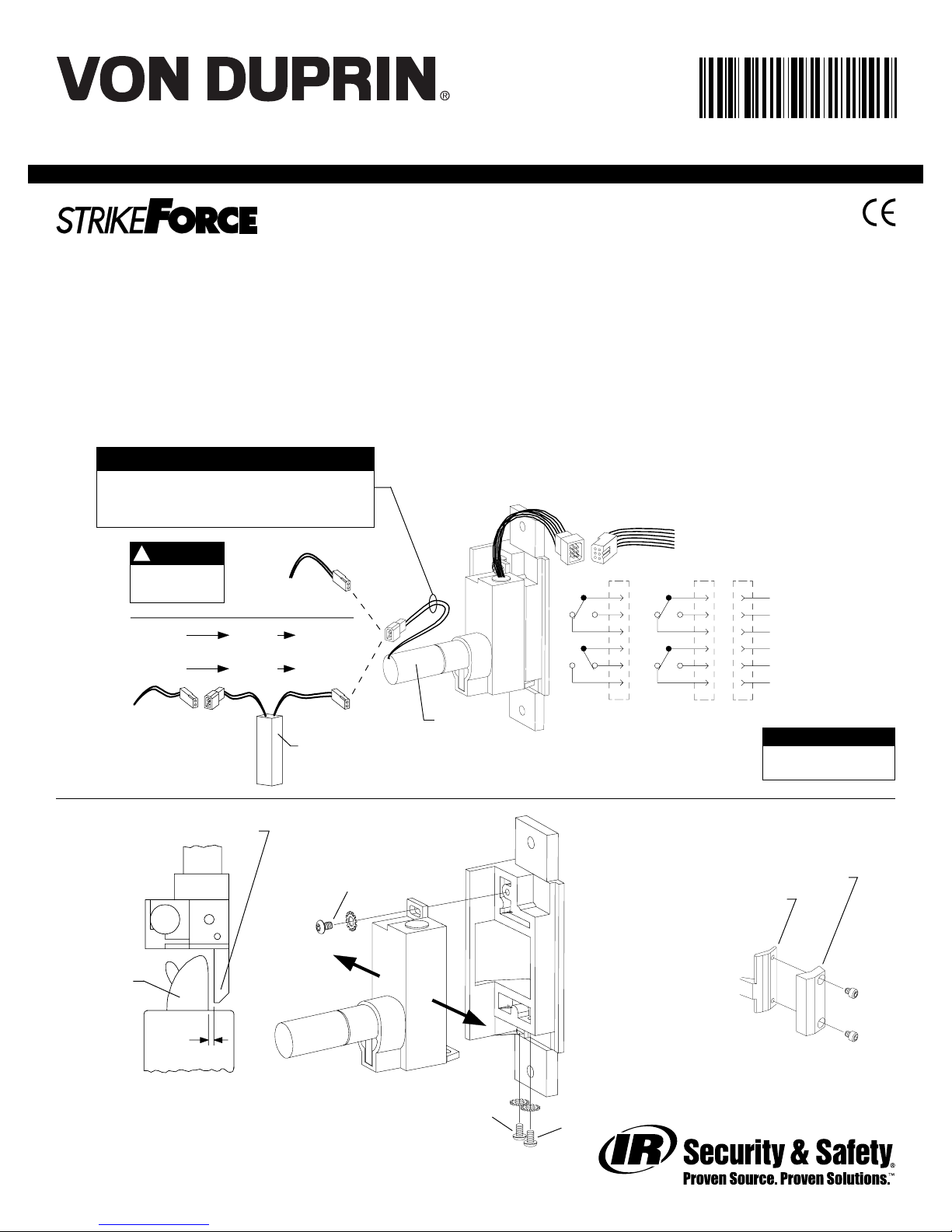
Figure 1
DC input is
nonpolarized.
NOTE
!
J1
J2 P2
Switches shown with tripper
depressed, strike lip closed and locked
(switches and tripper on 6212WFDS only)
Usecrimpconnectorsto
splice field wiring to P2
leads;insulateunusedleads
P1
P1 J1A P1A
SO-12or SO-24
12VDC
or
24VDC
12 VAC SO-12 12 VDC
or
24 VAC SO-24 24 VDC
{
{J2
Fail safe (FS)
J2
Fail secure (FSE)
S1
S2
1
2
3
4
5
6
S1
S2
1
2
3
4
5
6
Wiring
for DC
supply
Wiring
for AC
supply
4. Teststrike: Apply solenoid power.Fail secure (FSE) lipunlocks.
Fail safe (FS) lip locks. Figure 1 shows status of switches.
5. Installstrikewith two #12-24 screws. Make sureclearance
between latch bolt and strike lip is 1/32” (Figure 2). If not,
uninstallstrike, adjust (Figure 3), and reinstall.
6. If latch bolt does not extend far enough to actuate tripper,
installextension (Figure 4). (Tripper on 6212WFDSonly.)
7. Testdoor:With strike unlocked, door opens withlatchbolt
extended. When door closes, latch bolt rides over strike lip.
931222_00(6) Copyright © 2004Ingersoll-Rand. All rights reserved.
Solenoid
89/336/EEC
Standard: 5 A, 30 VDC
Gold: 0.25 A, 30 VDC
SWITCH RATINGS
}
P2
Red (C)
Blue
Yellow
White (C)
Gray
Violet }
S1
(monitors
tripper)
S2
(monitors
strike lip)
Usecrimp
connectorsto
splice field wiring
toP1 leads
Tripper
Figure 4
Extension
Figure 2
Topview;
faceplatenot
shownforclarity
1/32”
Latchbolt
Strike lip
Yellow solenoid wires = 12 VDC, 0.57 A
Black solenoid wires = 24 VDC, 0.29 A
(alsoshownon strike label)
SOLENOID POWER REQUIREMENTS
Figure 3
Toadjuststrike,
loosen screws A, B,
and Cand move
backboxsideways
asnecessary
A
BC
Notes: Deadbolt will not function with this strike.
Checkwithfactoryforretrofitapplications.
1. Forlockordevicepreparation,seetheir directions.
2. Prepare frame for strike (see other side).
3. Wire strike (Figure 1). (Switches on 6212WFDS only.)
Single Door Wood Frame Mortise or Cylindrical Application
931222-00


 98/99-2 User manual")


