1. TECHNICAL PARAMETERS
S/N PARAMETERSPROJECT
1 Project Model
Input Voltage
Current Rating
Power Rating
Frequency Rating
IP Grade
Working Temperature
Ambient Humidity
Altitude Permission
Operating Instructions
SETX-1-22-7-AC-02
230VAC±10%
32A
7KW
50Hz±5%
IP55 (Outdoor)
-40°C~+65°c
0~95% non-condensation
≤2000m
LED
2
3
4
5
6
7
8
9
10
6. PACKAGE LIST
S/N
SPECIFICATIONS NOTENUMBER
NAME
1AC Wall Charger
Product description
Ziplock bag
Anti-the screws
Combining screws
Bolt
Internal forced expansion anchor
Mounting board
Hook
Plastic expansion tube
M4 x 10 with lock core
M6 x 12
M6 x 16
M6 x 25
145 x 145 x 250
75 x 45 x 60
M6 x 30
2
3
4
5
6
7
8
9
10
11
1
1
1
2
4
4
4
2
1
3
3Self-tapping screw M4 x 30
5. FACTORY INSPECTION LIST
S/N ACCEPTANCE CRITERIA RESULTSITEM
1Interior Appearance
Overall Appearance
Function Check
Charging Connector
Accessories Package
Package Inspection
The writing is correct, the screws
are fastened
Visually free of appearance
defects, fully identified
General on check, short-circuit
check, ground check
Insulation resistance and
dielectric strength
Power-on light with on-board
charging
IEC 62196-2
Complete materials,
no omissions
OK
OK
OK
OK
OK
OK
OK
Complete materials,
no visual defects
2
3
4
Electrical Inspection
Safety Check
5
6
7
8OK
S/N NAME
1 Electric impact drill
Scale (5m)
Electrician gloves
Cross screwdriver
Inner hex wrench (5mm)
PVC insulation tape
T15 Anti-the wrench
2
3
4
5
6
7
7.2 Installation Tool List
3. OPERATING INSTRUCTIONS
STEP 1: INSERT CHARGING CONNECTOR
Remove the charging connector from the wall charger and
connect to the vehicle inlet. When the connection is successful, it
will display a steady blue light.
STEP 2: CHARGING
When the charging process starts, the light on the wall charger will
begin to flash blue.
STEP 3: CHARGING COMPLETE
When blue light stops flashing the charging is complete. Pull the
charging connector out of the car and position it back on the wall
charger. The indicator on the wall charger will display a steady
green light.
7. INSTALLATION GUIDANCE
7.1 Installation Precautions
Before installing, read the installation instructions carefully, paying special
attention to the following:
1) This wall charger installation needs to be carried out by a professional in
strict accordance with the installation steps and standards of construction.
Non-qualified installers may cause damage to the wall charger and
improper installation of the wall charger will invalidate the warranty.
2) If the site to be installed is under construction do not install immediately, to
avoid damage to wall charger with building materials, dust, paint, etc.
3) Before wiring ensure the power is turned o.
4) Wall charger uses a dedicated power supply or interface. Must be good
ground and fire zero wiring is strictly prohibited to reverse.
5) When installing, wear protective gloves to prevent injury.
6) Please use correct attachments for installation, the installation of expansion
bolts and wall holes must be closely coordinated.
NOTE: Before installation,please follow the packing list and check the components are complete.
If not complete,please contact the company in a timely manner.
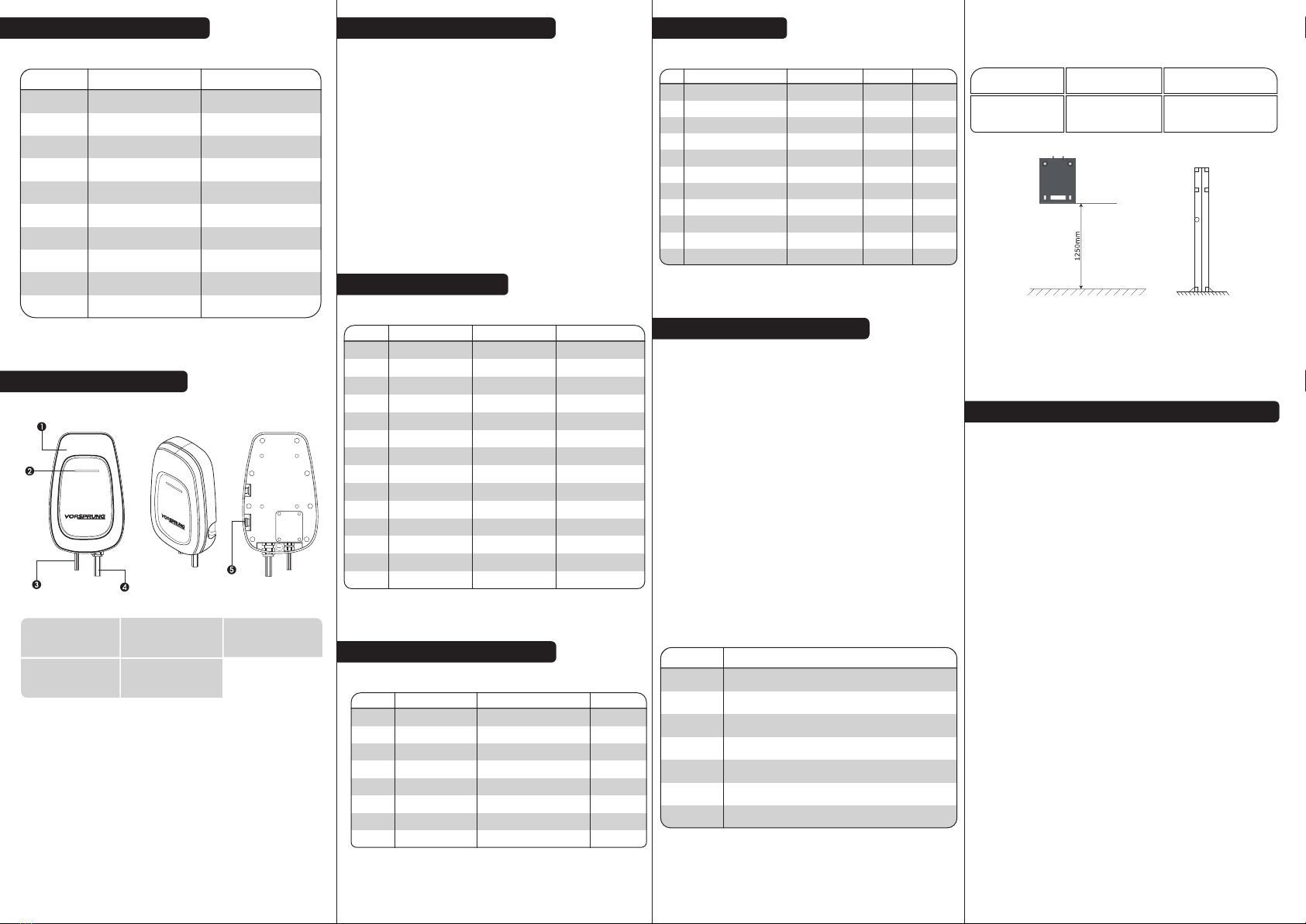
2. PRODUCT STRUCTURE
NOTE:Do not use the emergency stop button as a stop switch,if the emergency stop button is
pressed, please reset it by twisting the button clockwise.
1. UPPER COVER 2. LED LIGHT 3. POWER CABLE
4. CONNECTOR
CHARGING 5. STOP BUTTON
EMERGENCY
7.3 Positioning Installation
The corresponding fastening bolts should be prepared prior to installation, with the
following parameters:
Use the wall mount or column to detemine the installation postion
(recommended height of 1250mm). Then screw the mounting board onto the wall
or column and fix the wall charger onto the plate.
SCREW MODEL NUMBER USE
M6 x 25
(Inside Force
Expansion Anchor)
Installation of wall panels
to wall or column to the base
4
8. INSTALLATION & WIRING INSTRUCTIONS
Needs to meet the following requirements:
1) The wall charger should have a separate distribution circuit
and should not be shared with other electrical products.
2) 7.0KW inlet cable requirements of 6mm inlet crimping
terminal.
3) In order to prevent electric shock, ensure the input ground is
securely grounded in accordance with the installation
instructions. Prohibit use of multiple core plugs in front of the wall
charger.
NOTE:Must be installed and tted by a qualied tter.
4. LIGHT DESCRIPTION
S/N LIGHT LIGHT RESOLUTIONACTION/STATUS
1 Standby
Plug in the gun
Charging
Fully Charged
Pull out the connector
Emergency stop
CP abnormal failure
Short circuit fault
Steady Green
Steady Blue
Blue Flashing
Steady Blue
Steady Green
Standby
Connected to the car end
Charging
Charging is complete
Standby
Failure Red light flashes
(1 fast and 1 slow)
Red light flashes
(2 fast and 2 slow)
Red light flashes
(5 fast and 2 slow)
Red light flashes
(2 fast and 1 slow)
Red light flashes
(4 fast and 1 slow)
Red light flashes
(3 fast and 2 slow)
Red light flashes
(6 fast and 2 slow)
Red light flashes
(3 fast and 1 slow)
Red light flashes
(5 fast and 1 slow)
2
3
4
5
6
7
8
9
10
11
12
13
14
Overcurrent fault
Overvoltage fault
Under-voltage fault
Adhesion failure
Leakage fault
Leakage self-test failure
Emergency stop is pressed
CP voltage is abnormal
Output short circuit
Abnormal current
Abnormal voltage
Abnormal voltage
Output adhesion
Leakage
Leakage self-test failure