Vpon VP-102 Instructions for use

Network DVR on Chip
Your best choice for digital video recording and remote surveillance
VP-102
Intelligent PCI-E DVR Kit
Hardware User Manual
(Version:V1.4.3)
Introduction
Installation
Appendix
www.vpon21.com

Preface
Preface
Notice
The information in this manual was current when published. The manufacturer reserves the right to revise and improve its
products. All specifications are therefore subject to change without notice.
Note: Formosa21 will not be obligated to the responsibility outside the scope of VPON DVR.
Trademarks
VPON ® is a registered trademark of Formosa 21 Inc.
Microsoft, Windows, Internet Explorer ® are registered trademarks of Microsoft Corporation. Netscape, Navigator,
Communicator ® are registered trademarks of Netscape Corporation. Other brand and product names referred to in this manual
are trademarks or registered trademarks of their respective holders.
Trademarked names are used throughout this manual. Rather than place a symbol at each occurrence, trademarked names are
designated with initial capitalization. Inclusion or exclusion is not a judgment on the validity or legal status of the term.
Warning
To reduce risk of electric shock, do not remove cover. No user service-able parts inside. Refer servicing to qualified service
personnel.
Do not expose this appliance to rain or moisture.
Do not install this product in hazardous areas where highly combustible or explosive products are stored or used.
Severe impact or vibration may cause malfunction.
Do not move this product when VPON is working.
Position it in an open space with flat surface, and also maintain at least 15 cm between the left and right sides of the
body and the wall.
The lightning flash/arrowhead symbol, within and equilateral triangle, alerts the user to the presence of a shock hazard within
the product’s enclosure.
CE Warning
This is a Class A product, in a domestic environment this product may cause radio interference in which case the user
may be required to take adequate measures.
FCC Warning
This device complies with Part 15 of the FCC Rules. Operation is subject to the following two conditions (1) this
device may not cause harmful interference, and (2) this device must accept any interference received, including
interference that ma
y
cause undesired o
p
eration.
GUARANTEE
Every care has been taken in the preparation of this manual; if you detect any inaccuracies or omissions, please inform
FORMOSA21, INC. in Taiwan or your local distributor. FORMOSA21 cannot held responsible for any technical or
typographical errors and reserves the right to make changes to the products and manuals without your prior notice.
FORMOSA21 makes no warranty of any kind with regard to the material contained within this document, including, but not
limited, the implied warranties of merchantability and fitness for a particular purpose. FORMOSA21 shall not be liable nor
responsible for incidental or consequential damages in connection with the furnishing, performance or use of this material.
Important information
Before proceeding, please read and observe all instructions and warnings contained in this manual. Retain this manual with the
original bill of sale for future reference and, if necessary, warranty service.
When unpacking your VPON unit, check for missing or damaged items. If any item is missing, or if damage is evident, DO
NOT INSTALLOR OPERATE THIS PRODUCT. Contact your dealer or us for assistance.

Table of Contents
Table of Contents
1. Introduction
1.1 Features-----------------------------------------------------------------------------------1
1.2 Product Specifications ----------------------------------------------------------------------------------------2
2. Getting started
2.1 Summary of the installing ------------------------------------------------------------------------------------3
2.2 Installation ------------------------------------------------------------------------------------------------------3
2.3 Power on --------------------------------------------------------------------------------------------------------5
2.4 Configuration -------------------------------------------------------------------------------------------------- 5
2.5 Connecting to network ----------------------------------------------------------------------------------------5
2.5.1 Remote access using dial-up ------------------------------------------------------------------------------- 6
Appendix:
A: Recommendation Motherboard ------------------------------------------------------------------------------------I
B: Operation Via local keyboard ------------------------------------------------------------------------------------- II
C: IrDA mode (IR Remote Control) -------------------------------------------------------------------------------- IV
D: Watch-dog Wiring Description -----------------------------------------------------------------------------------VI

Chapter1. Introduction
1
Chapter 1. Introduction
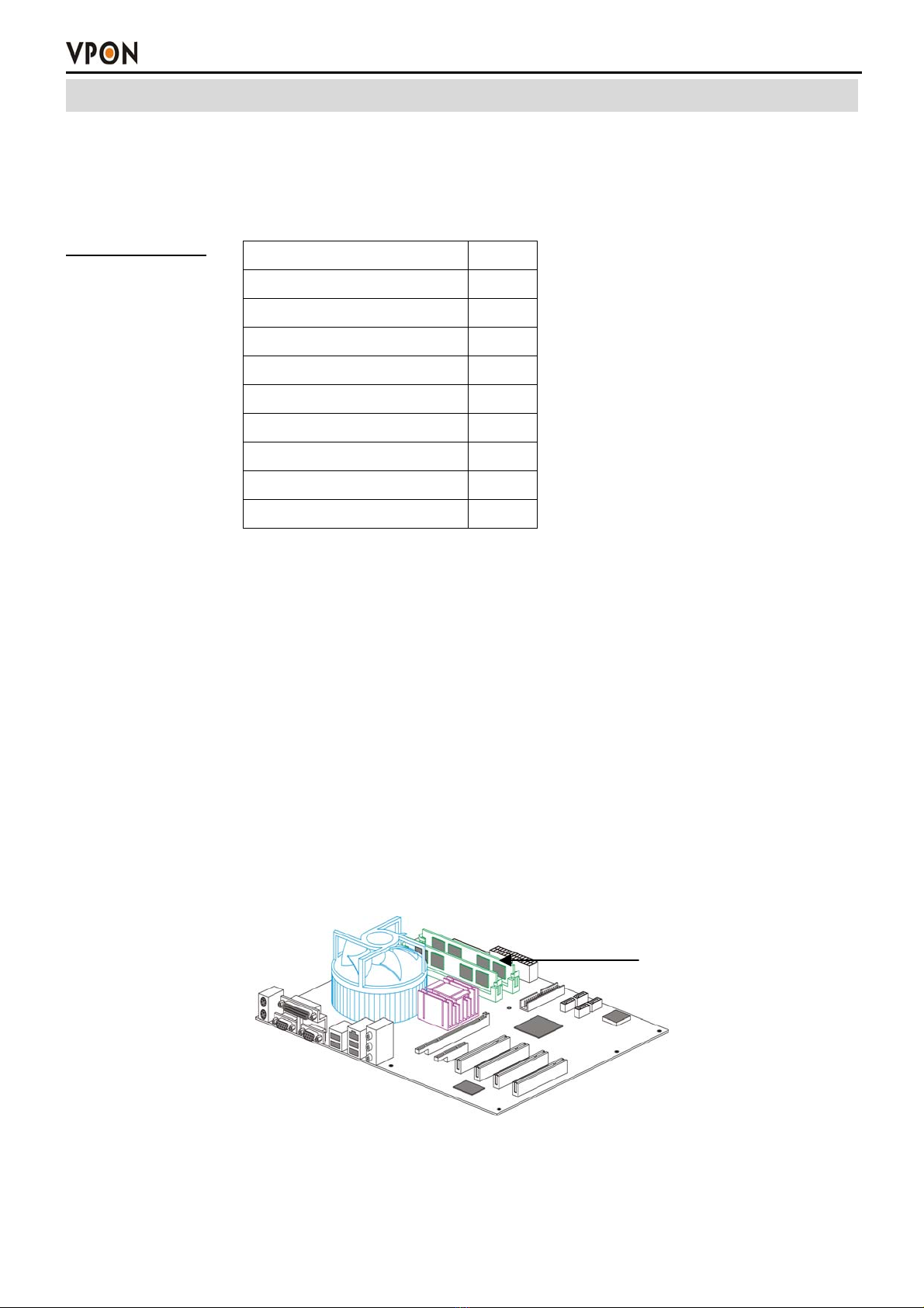
A VP-102 package includes one VP-42 PCI-E video capture card and a DVR on chip DOM. VP-42
supports 8 camera and Audio input ports. After install them in a PC, it becomes a dedicated DVR system
after power up. The DVR System is a high performance digital video recorder with built-in mini web
server and real-time video capturing capability. The video is grabbed and compressed for faster
transmission to your PC through 10/100Mbps Ethernet. The video also can display through local VGA
output . Besides, VP-102 supports digital recording function. It can record / playback / browse video
simultaneously and save video data by cyclic recording to PC hard disk.
VP-102 supports full motion live video and audio through Internet, Intranet connection. When supporting
more than 8 camera ports, extra VP-42 cards can be installed on the same PC of VP-102. A DVR on chip
DOM can support maximum 2 VP-42 capture cards. This makes the PC supporting up to 16 cameras.
After installing VP-102, the PC is ready as a DVR. When power up, it starts local DVR functions such as
monitoring through VGA output and recording to hard disk if it is configured to do that. For remote
monitoring or access to historical data, you will have to set up the LAN or Internet environments and
configure VP-102 IP information. When all these installation are done successfully, VP-102 delivers
real-time full-motion audio/video transmission to anywhere anytime. A PC with Internet browser and our
proprietary plug-ins software can do that. The camera can be remotely controlled to do zoom in and out,
and the unit can be triggered to initiate certain events. Configuration of VP-102 can be done by an IR
remote control unit or a mouse .
1.1 Features:
Video & audio live surveillance
Simple and smart operation with IR remote control.
Up to 30 fps on each camera for local monitoring.
VPON Network DVR Firmware in a DOM (Disk On Module)
Adjustable recording quality for each camera.
Two-way audio transmission.
1 / 4 / 6 / 7 / 8 / 9 / 10 / 13 / 16 split-screen display.
Control well known brand PTZ Cameras.
Different PTZ devices can work on same serial bus.
System log and Operation log support.
Record / display / playback simultaneously.
Local playback of recorded video on VGA or TV monitor.
Remote live monitoring and playback from PC browser.
High video quality and low data rate.
Multiple video compression engines: MPEG4, H.263, JPEG, M-JPEG
Recording & Playback
Water mark to prevent fraud image modification
Adjustable recording rates and resolution for each camera
Motion detection / Alarm trigger / Cyclic / Schedule / Weight recording
Pre-motion or pre-alarm and post-motion or post-alarm recording
Adjustable recording frame rates when motion or alarm was triggered
Brightness and color adjustment during playback
Digital Zoom-in during playback
Thumbnail browsing support

Chapter1. Introduction
2
Bookmark function support
Searching by time, day, motion, events or alarm log.
SCSI/USB/IDE RAID and NAS storage system support
Alarm function
System audio alarm warns when alarm was triggered
System automatically displays corresponding enlarged image when alarm was triggered
Snapshot images through E-mail or FTP server when alarm was triggered.
Optional GPI/O for alarm control.
Network
Browser-based, no remote viewing software needed.
Access prohibition for pre-defined hosts through IP network
Dynamic IP support for Internet access
Direct Dial-up available and Low-bandwidth support
Easy to use
Plug and recording, non-Windows embedded Linux system
Easy configuration via local keyboard, IR Control, Home Page or Mouse
Standard web browser as the client application
Customization
Supports HTML file upload for home page customization
Supports FTP Server upload for customization
Support backup configuration file
Support POS/ATM integration
1.2 Product Specifications:
Model VP-102
Channels/Card 8
Display FPS/Card 240fps
Rec. FPS/Card (320X240) 200fps
Rec. FPS/Card(640X480) 160fps
Audio In/Card 4
Alarm In/Card 8
Control Out/Card 4
Compression Standard MPEG4 / JPEG / M-JPEG / H.263
Minimum System Requirement Pentium IV 2.6GHz CPU or better
512MB DRAM,
One IDE slot for DOM Chip
PCI-Express VGA card
Browser Compatibility Win 98/ME/2000/XP running MS Internet Explorer 6.0 or
later
Communication Protocol Support TCP/IP, DHCP, NTP, HTTP, FTP,UPNP
Backup Function IDE or USB Interface HDD, CD-RW, DVD+RW
Language English, Traditional Chinese

Chapter 2. Getting Started
3
Chapter2.GettingStarted
2.1 Summary of the installing
Before install VP-102 to your PC platform, please make sure the PC’s Hardware is compatible with the
motherboards, which we have recommended in the appendix.
VP-102 contains : Description Quantity
VP-42 Video Capture Card 1
Video & Audio cable 1
DVR on chip module (DOM) 1
IrDA Controller & receiver 1
Manual CD 1
Hardware user manual 1
Yellow IDE Cable 1
Watch dog Wire 1
Battery 2
2.2 Installation
Step 1 : Installing Motherboard
We recommend motherboards that support Linux device drivers. If you purchased a non-recommended
motherboard yourself make sure it works. We are not responsible for non-approved motherboards. We
carry recommended motherboards for system integrators to use. Put the motherboard together just like a
regular PC.
Step 2: Installing CPU
We recommend any Pentium 4 Class CPU. Install as usual and attach the heat sink and fan.
Step 3: Installing Memory
We recommend installing a good brand name 256MB DDR memory.
NOTE: If you choose MPEG4 compression standard, please install 512MB DDR memory.
DDR Memory
Step 4 : Installing VGA Card
We recommend VGA cards as in supporting list (Please check appendix) .We carry VGA cards for system
integrators. Insert the VGA card into the PCI-Express slot. Not all VGA cards will work due to
unsupported Linux device drivers.

Chapter 2. Getting Started
4
Step 5: Installing VP-42 Video Capture Card
Our video capture card is proprietary and will only work with our DVR chip. Install the video capture
card into an available PCI-E slot. Once the system boots the VPON firmware will automatically detect
how many video capture cards are in the PCI-E slots.
Step 6: Installing the hard drives
For a single drive make sure the jumper settings is set on primary. Attach that with any ordinary IDE
cable onto the secondary IDE channel. For dual drives make sure one hard drive is set on primary and the
secondary on slave. Attach those to the IDE cable and plug into the secondary IDE channel. The max hard
drive size supported is 500GB each. For a total of 1TB.
Note: When VP-102 based DVR is working for the first time, the system will erase the data in the hard
disk. If there is important information in the hard disk, please remember to backup the data in another
storage before the hard disk is used in the VP-102 based DVR.
Step 7: Installing the VP-102 DVR module
The VP-102 DVR module sits on the primary IDE slot on the motherboard. If attaching a CD-RW to your
unit then put the VP-102 DVR module in the middle of the yellow IDE cable included. And then put the
end of the yellow IDE cable to the CD-RW and the other end to the primary IDE channel. The yellow
IDE cable must be used with the VP-102 DVR module and not any generic IDE cable. Then attach the
power connector from the VP-102 DVR module to a free lead from the power supply.
VP-42 Video Capture card
DOM (VP-20)

Chapter 2. Getting Started
5
Power Supply
We recommend using a 400W ATX power supply for the DVR unit.
2.3 Power On
After complete the installation , you can power on the PC as usual. Live videos should be displayed on
VGA screen if everything is OK.
2.4 Configuration
When you get videos display on VGA screen, you can configure the VP-102 PC DVR unit using mouse
or the IrDA controller comes with the VP-102 package. Please refer to User manual “Chapter 3
operating VPON by mouse , Chapter 4 Operating VPON by IrDA controller.
Change from GUI mode to IR mode
Default operation mode is GUI mode. VPON provides a GUI mode with mouse support. Be sure to plug
in a PS2 mouse at the back of the unit before or when it starts to boot. Go to the running mode in the
system settings. Change it from mouse mode to IR mode. The unit will reboot. Mouse mode is the only
mode where a log can be found.
2.5 Connecting to the network
Connect an Ethernet-capable computer to the VPON LAN port using an RJ-45 crossed UTP cable or
connect both of the PC and VPON to a same hub :
1. The default IP address for the VPON is 192.168.10.10. Set your PC IP address to 192.168.10.xxx
(where xxx is a value between 0 ~ 254). Set the subnet mask to 255.255.255.0.
2. Reboot the PC.
3. Use IE Web browser version 6.0 SP2 up to access http://192.168.10.10. The login dialog box will
appear. If you have previously changed the administration login or password, enter the login name
and password you previously set. Otherwise, enter the default login name “webmonitor” and the
password “oyo” then click OK.
4. For first time accessing VPON , you will be prompted to install Live Video ActiveX. Download and
run the file to install ActiveX. Then restart IE browser, you will be able to see the videos. If you
choose not to install Active X, you can view videos from the VPON by clicking on the View Video
without Plugins link at the bottom of the page. At the prompt, enter the same administrator login
name and password as before. This uses a Java applet to display the video.
2.5.1 Remote access using dial-up
You can access the VPON remotely without the Internet by using a dialup modem. The VPON must be
working under Network mode.
1. Connect a dial-up modem and phone line to the VPON COM1 port.
2. Set COM1 to modem device in the VPON system menu.
3. On the remote PC, create a new dial-up setting (Windows).

Chapter 2. Getting Started
6
4. Set the protocol to PPP.
5. Clear all advanced options and allowed network protocols except TCP/IP.
6. Set the IP address to 10.0.0.2.
7. Put a check mark in the server assigned server address box, uncheck “use IP header compression” and
“use default gateway” on the network boxes. Then click OK.
8. Enter the number of the phone line connected to the VPON, as well as the administrator user name and
password.
9. To access the VPON, use IE 6.0 SP2 up. Bring up IE on the PC and then access to 10.0.0.1.
Note: As this is a PPP connection, only one user can access the VPON at a time.

Appendix
I
Appendix A: Recommendation Motherboard
We have tested some different motherboards for VP-102. If You are first time to plug and play
VP-102.We suggest you to choose the motherboard which have been tested by us for better
performers。
Suggesting CPU model:
Pentium 4, 1.6G or better
Motherboard:
1. North bridge:Intel chipset
2. South bridge:ICH2, ICH4, ICH5 & ICH5R
3. Others:We need 5 PCI slots at the least for expand
Memory :
DDR 256MB or above
DDR512MB for MPEG4 compression standard
PCI-Express VGACards :
nVidia Geforce NX62/00/NX6600 (mouse mode only)
ATI X300SE (VGA Monitor only)
Motherboard:
Socket 775 Motherboards* (M/B)
Motherboard Brand & Model # Chipset
VPON VP-MB945G Intel 945G
GIGABYTE GA-8I945P-G Intel 945P
GIGABYTE GA-8I915P DUO Intel 915P

Appendix
II
Appendix B: Operation via local keyboard
To get VP-102 up and running via local keyboard, a keyboard is required. The interface of VP-102
operation is as following figure.
1 2~13
14 15 16 17 18 19
1. Esc: Cancel
Provide cancel and close function. When pressing “Esc”, it will close current setting menu and
returns to the previous level.
2. F1: Menu
Provide main menu display function. When users press “F1”, it will display the main menu on the
screen, and press “Left/ Right/ Up/ Down” button to select, and then press “Enter” for confirmation.
3. F2: Playback
Press “F2” to enter playback list, and press “Up/ Down” button to select the recorded file, and then
press “Enter” or “F5” to play the video.
4. F3: Local (view live image immediately)
When pressing “F3”, users can view the live image immediately.
5. F4: Screen
Press “F4” to switch display setting from Single, Quad, 8 splits and 16 splits. Press “Up/ Down”
button to select, and then press “Enter” to make sure the selection.
6. F5: (Play)
When pressing “F5”, the recorded data will start to play. Users also can press “F5” to skip the crash
video and play next time period continuously.
7. F6: (Pause)
When pressing “F6”, users can pause the playing video.

Appendix
III
8. F7: (Stop)
When pressing “F7”, users can stop the playing video.
9. F8: Speed (switch playing speed)
When pressing “F8”, users can switch the playing speed.
10. F9: (Seek Backward)
When pressing “F9”, users can backward seek the video.
11. F10: (Step Backward)
When pressing “F10”, users can backward the video frame step-by-step.
12. F11: (Step Forward)
When pressing “F11”, users can forward the video frame step-by-step.
13. F12: (Forward)
When pressing “F12”, users can forward seek the video.
14. S: Speed (same us “F8”)
The function is the same as “F8”.
15. D: Display
When pressing “D” in playback mode, users can view the status of video, GPI, Motion Detection,
progress in bar chart at the bottom of the screen.
16. Space: Step Backward/ Step Forward
When playback the video, users can press space bar to step backward or step forward seek the video.
17. Enter: Play/ Pause/ OK
This button is used to store the setting values in the setting menu. Besides, when playback the video,
users can press “Enter” to continue or pause the playing.
18. Up/ Down/ Left/ Right Button
When pressing these buttons, users can control the directions of cameras or adjust the parameters of
the setting menu.
19. Page Up/ Page Down: Previous Page and Next Page
In the setting menu, users can press “Page Up/ Page Down” to change the setting menu page.
Note: About the detail operation of VP-102, please refer to VPON series support CD with the
standard package.

Appendix
IV
Appendix C: IrDA mode (IR Remote Control)
Users can operate VPON via IR remote control or local keyboard. There will be an OSD screen on the
VGA monitor. Before operating VPON via IR remote control, please make sure that VPON has connected
to the VGA monitor via VGA Out connector.
A N
B M
C L
DJ
K
E
FI
G H
A. TV button
Exchange video monitoring from VGA to TV. Press the TV button until hear ” bee bee “sound after
few minutes VP-102 will auto-reboot to change to TV monitoring.
B. Menu button
Displays the main menu.
C. Cancel button
Closes the menu and returns to the previous screen.
D. Up/Down/Left/Right button
Controls direction.
E. Speed/Play/Pause/Stop/Rewind/Seek Backward/Seek Forward/Fast Forward
Used only for playing back video recorded by VPON.
F. Number keys
Used to input number selections.
G. Contrast Setting button
Creates contrast colors on screen.
H. Color Setting button
Controls darkness and lightness of video images.
I. Display button
Switches display status.

Appendix
V
J. Prev/Next Page button
Moves from current screen to the next or previous screens.
K. OK button
Sets the settings.
L. Keypad button
Brings on screen the keypad function.
M. Mode Switch button
Remote, Playback, and Local buttons allow users to switch the display status. Remote is not used
on the VPON series. Playback plays back the recorded files. Local allows users to view the live
image immediately.
N. Screen Display
Change display mode to single or quad. The In turns button is not used for the VPON series.
The IR remote control has four gray triangular buttons surrounding the OK button, resembling a baseball
diamond. These are the primary buttons that you will be using the majority of the time.
Gray “baseball diamond” button functions:
The Top and bottom gray triangular buttons highlight the selections.
The OK button is used to save information into the system.
The Right triangular button accesses the highlighted line.
The Left triangular button is usually used to move backwards.

Appendix
VI
Appendix D: Watch-dog Wiring Description
Watch dog is a hardware device to monitor the system status. If the system fails to response, Watch dog
will send a rest signal to the motherboard to reboot the system. To enable Watch dog function, please
select available durations 10,9,8…..seconds.
Hardware Request list:
1. One pair of conducting wire (2-pin to 2-pin). (Cable A)
Installation Step:
1. Attach the pair of conducting wire (cable A) from video capture card JP1 PIN1,2 to the RESET
JUMPER on Motherboard.
2. Use a RS232 null modem cable to build up the connection between COM1 port of PC and VPON.
3. Run WCOMW.EXE and it will show up the “Network Mode Configuration Menu”. As bellow :
3. Select the item 7 on “Network Mode Configuration Menu” then press “Enter”, it will do watchdog
functional test in VPON and display message "10 9 8 7 6 5 4 3 2 !!Reboot!!" on the screen.
4. Exit Configuration Menu to stop WCOMW.EXE, When DVR reboot to ready, the test is completed.
Table of contents
Other Vpon DVR manuals