Printed On Recycled Paper
VULCAN-HART COMPANY, P.O. BOX 696, LOUISVILLE, KY 40201, TEL. 1-800-814-2028
502-778-2791 QUOTE & ORDER FAX: 1-800-444-0602
NOTE: In line with its policy to continually improve its products, Vulcan-Hart Company reserves the right to change materials and
specifications without notice.
F-32620 (8-06)
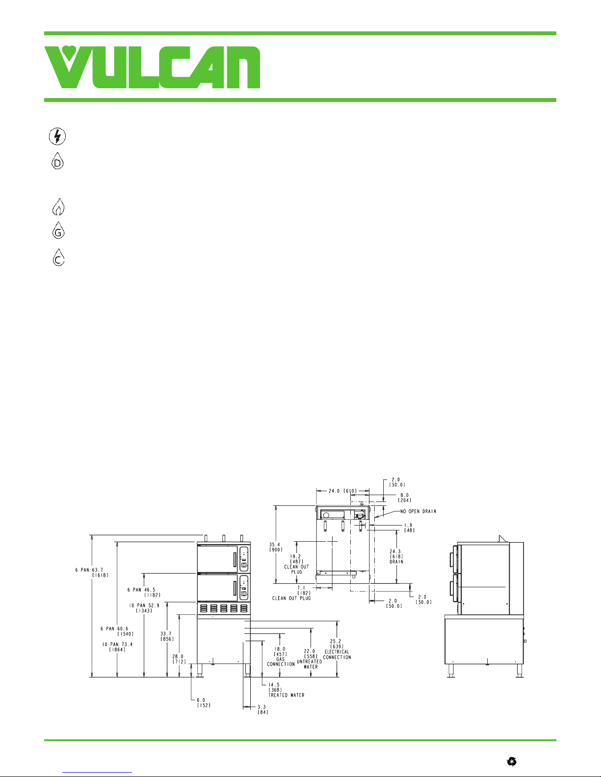
MODEL C24GA SERIES
GAS CONVECTION STEAMER ON CABINET BASE
SERVICE CONNECTIONS:
Unless otherwise specified, Field Wire Electrical Connection to
be 120/60/1 with grounding wire. Maximum amps 2.0.
DRAIN: Condenser box, compartment and generator, 11/2"
NPT. (Provide an open air gap type drain within 12" of con-
denser box and for best results at a distance so steam vapors
will not enter the steamer from underneath the control area. Do
not connect solidly to any drain connection.)
GAS CONNECTION: 3/4" NPT. O.D. supply line required.
GENERATOR WATER SUPPLY: 3/4" Hose Bib fitting at
25-50 PSI (170-345 kPa).
CONDENSING WATER SUPPLY: 3/4" Hose Bib fitting at
25-50 PSI (170-345 kPa).
WATER QUALITY STATEMENT:
The fact that a water supply is potable is no guarantee that it is suitable for
steam generation. Your water supply must be within these general
guidelines:
SUPPLY PRESSURE 20 - 60 psig
HARDNESS* less than 3 grains
SILICA less than 13 ppm
TOTAL CHLORIDE less than 4.0 ppm
pH RANGE 7-8
UN-DISSOLVED SOLIDS less than 5 microns
*17.1 ppm = 1 grain of hardness
Other factors affecting steam generation are iron content, amount of
chloridation and dissolved gases. Water supplies vary from state to state
and from locations within a state. Therefore it is necessary that the
local water treatment specialist be consulted before the installation of
any steam generating equipment
IMPORTANT:
1. A combination valve with pressure regulator is provided with this unit.
Supply gas pressure should be a minimum: Natural gas 7"
W.C., propane gas 11" W.C.
2. Gas line connecting to unit must be 3/4" or larger. If flexible connectors
are used, the inside diameter must be at least the same as the 3/4"
iron pipe.
3. An adequate ventilation system is required for commercial cooking
equipment. Information may be obtained by writing to the National
Fire Protection Association, Batterymarch Park, Quincy, MA 02289.
When writing, refer to NFPA No. 96.
4. These units are manufactured for installation in accordance with
ANSZ223.1A (latest edition), National Fuel Gas Code. Copies may be
obtained from the American Gas Association, 1515 Wilson Blvd.,
Arlington, VA 22209.
5. Clearance: Combustible Non-Combustible
Rear 6" 0"
Left Side 0" 0"
Right side 0" 0"
NOTE:
•Dimensions which locate the above connections have a tolerance of
+ or - 3” (+ or - 75mm). Normal dimensions are in inches. Dimensions
in ( ) are in millimeters.
•Installation of backflow preventer's, vacuum breakers and other spe-
cific code requirements is the responsibility of the owner and installer.
It is the responsibility of the owner and installer to comply with local
codes.
•Plastic drains are not recommended due to inherent limited tempera-
tures of the plastic. Boiler purge temperatures may exceed 180ºF.
The installer may be required to provide means to reduce boiler
purge water temperatures to be that of the condensate temperature
of 140ºF or below.
•Do not connect this unit to a ground-fault circuit-interrupter (GFCI)
125-volt, single-phase, 15- and 20-ampere receptacle. Electronic burner
ignition systems are prone to nuisance tripping and possible ignition
failure.
•This appliance is manufactured for commercial installation only and
is not intended for home use.


