WABCO WÜRTH W.EASY Trailer Power User manual

Page 1of 21
W.EASY Trailer Power Rev. 2.0
- Manual -
Version:
03.07.2018

Page 2of 21
Contents
For your safety.......................................................................................................................................... 3
Safety instructions.................................................................................................................................... 3
Proper use................................................................................................................................................ 4
Scope of delivery...................................................................................................................................... 4
Technical data .......................................................................................................................................... 5
Environmental conditions ......................................................................................................................... 5
Explanation of icons.................................................................................................................................. 6
Available modes........................................................................................................................................ 6
Operation ................................................................................................................................................. 7
X1 –Trailer power supply via ISO 7638 ................................................................................................ 7
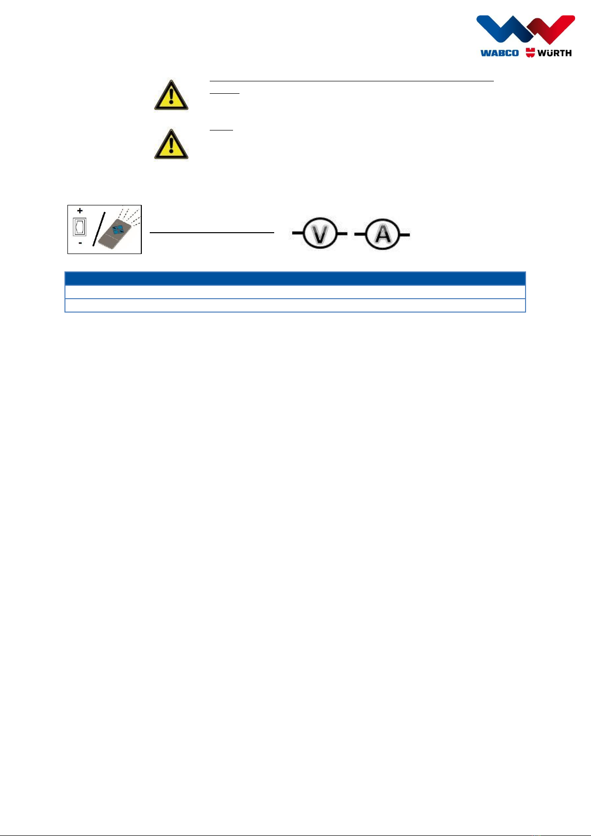
X1 –Signal test of the tractor control signals....................................................................................... 7
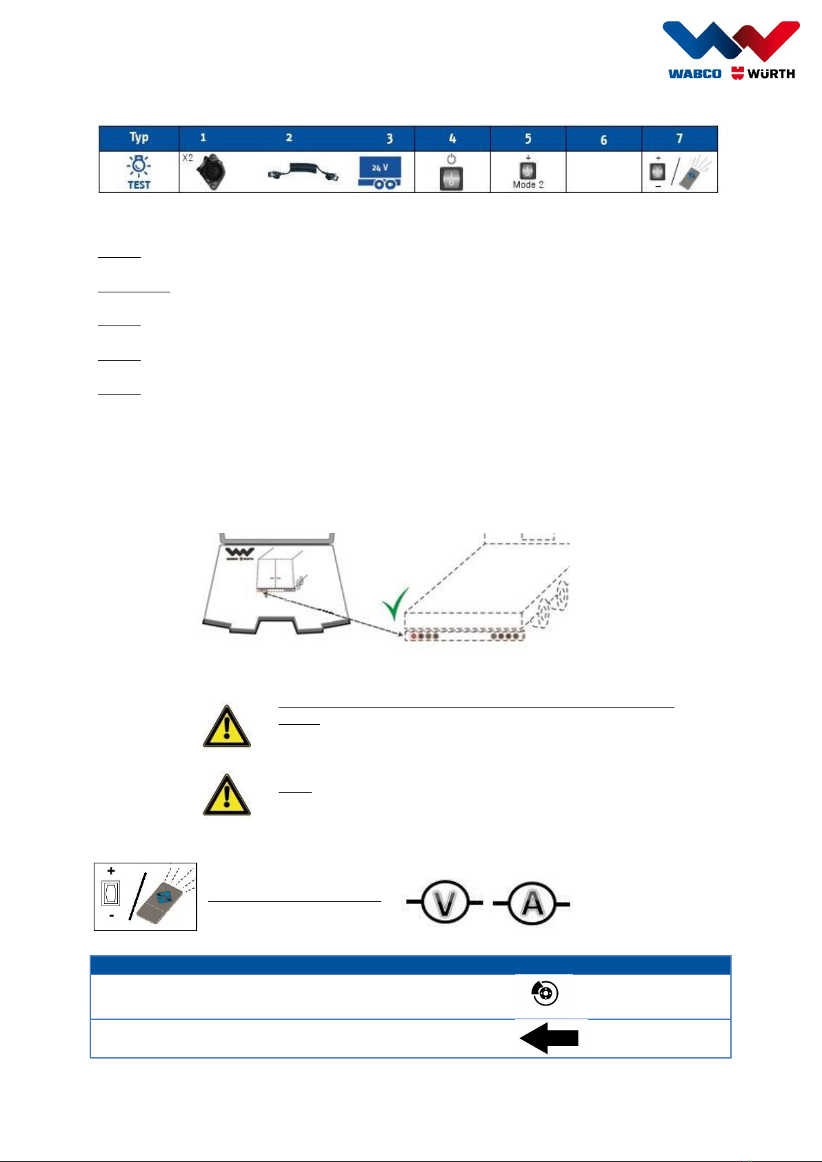
X2 –Trailer lighting test........................................................................................................................ 9
X2 –Signal test of the tractor control signals..................................................................................... 11
X2 –Pin test of pins 10–12 ................................................................................................................ 13
X1/X2 –Power supply + trailer lighting test ....................................................................................... 14
X1/X2 –Signal test of the tractor control signals............................................................................... 16
X3 –Trailer lighting test...................................................................................................................... 18
Equipment charging / Regular charging ................................................................................................. 20
Charging the equipment ..................................................................................................................... 20
The equipment must not be switched on for charging!Maintenance and cleaning................................... 20
Warranty................................................................................................................................................. 20
Environmental instructions ..................................................................................................................... 20
Batteries:................................................................................................................................................ 20
CE Declaration of Conformity ................................................................................................................. 21

Page 3of 21
For your safety
Please read these operating
instructions before you use your
equipment for the first time, and
handle the equipment as per the
instructions.
Please retain these operating
instructions for subsequent use or
for the next owner.
WARNING –You must read the
safety instructions prior to
commissioning!
Failure to observe the operating
instructions and the safety
instructions can lead to equipment
damage and pose a risk to the
operator and to others.
Inform the dealer immediately in the
event of damage caused by
transport.
Safety instructions
Note
It is forbidden to modify the
equipment or to produce auxiliary
equipment. Such modifications
can cause personal injury and
malfunctions.
Only trained, authorised persons
are permitted to perform repairs
on the equipment.
This ensures the continued safety
of the equipment.
Warning
High voltage and current inside the
equipment.
Warning
Maintain clearance of 1 metre
between the W.EASY Trailer Power
and the trailer, particularly when
transporting hazardous materials
(ADR).
Caution
Opening the electronic system or
the equipment will invalidate the
warranty.
Only use the equipment under
supervision! Always switch off the
equipment when the equipment is
unattended.
Warning
Temperature range:
-20°C < x < 55°C
The battery capacity drops in the
limit areas.

Page 4of 21
Proper use
Important note
W.EASY Trailer Power Rev.2.0 must only be used on 24V and 12V vehicles and their trailer
systems in accordance with proper use!
Note
The vehicles and the trailer systems must meet the country-specific specifications of the
relevant traffic regulations.
The equipment must be used for the following functions:
Power supply of the trailer electronics, 24V and 12V systems, via the following connections:
o7-pin ISO 7638 connection (24V system)
o13-pin ISO 11446 connection (12V system)
Test of trailer lighting as required via the following connections:
o15-pin ISO 12098 connection (24V system)
o13-pin ISO 11446 connection (12V system)
Test of the control signals for the trailer lighting coming from the tractor via the 15-pin ISO 12098
connection (24V system)
Control of PINs 10, 11 and 12 of the ISO 12098 connection as required with the following signals:
o24V voltage level
o0V voltage level/earth
Measurement of the voltages and/or currents at the individual PINs of the corresponding
connections:
oISO 7638 PIN 1 and 2
oISO 12098 PIN 1, 2, 3, 5, 6, 7, 8, 10, 11 and 12
oISO 11446 PIN 1, 2, 4, 5, 6, 7, 8 and 9
ISO 12098: Only use the connection on vehicles with 24V on-board voltage!
ISO 11446: Only use the connection on vehicles with 12V on-board voltage!
Use for any other purpose is considered improper use.
The user is liable for any damage ensuing from improper use.
Scope of delivery
W.EASY Trailer Power Rev.2.0
Power cable
Remote control
User guide (CD)
List of fault codes

Page 5of 21
Technical data
Description
Value
Operating voltage/on-board voltage
24V DC/12V DC
Weight
12 kg
Dimensions (W x H x D) in mm
580 x 210 x 490
Built-in fuse (short-circuit protection)
30 A (not self-restoring)
Built-in fuse
6–8 A (self-restoring)
Connections
Non-heating socket (power cable connection)
ISO 7638
ISO 12098
ISO 11446
Remote control
Dimensions: Approx. 82x39x17 mm
Weight: Approx. 40 g including
battery
Transmission frequency: 868.30 MHz
Modulation: AM
Transmission channels: 4
Range: Up to 100 m
Operating voltage: 12V alkali battery
(type 23A)
Current consumption: Typ. 20 mA
(transmission)
Battery
Nominal voltage: 2 x 12V = 24V
Charge time: 8–24 hrs
(depending on age)
Capacity: 7 Ah
Corresponding to average use in an application
with approx. 8 hrs continuous use
Charging:
Nominal voltage: 230V ± 10%
Power frequency
50 Hz
Max. current consumption
0.8 A
Environmental conditions
Description
Value
Air humidity
Max. 85%
Altitude
Up to 2000 m
Contamination index (IEC 61010-1:2)
Class 2
Overvoltage category (IEC 61010-1)
II
Permissible ambient temperature:
Charging:
Discharging:
Storage:
-15C to +50C
-15C to +60C
-20C to +50C

Page 6of 21
Explanation of icons
Name of mode
Icon
Function
Modulator Power
Power supply via permanent positive
and ignition
Truck Test
Test of lighting control signals from
the tractor
Light Test
Test of the trailer lighting
Pin Test
Activation of freely assignable PINs
10–12 on the 15-pin socket with
either 24V or 0V (earth)
Available modes
Mode
Name of mode
Function
System type
0
Standby
Detection of connected cable
1
Truck Test
Signal test X1
24V
Signal test X2
24V
2
Light Test + Power
Modulator Power (X1)
24V
Light Test (X2)
Modulator Power + Light Test (X1 +
X2)
3
Pin Test
Pin Test (X2)
24V
Modulator Power + Pin Test (X1 + X2)
24V
4
Light Test + Power
Modulator Power + Light Test
12V
Connected elements
Available modes
Switching per mode
X1
0, 1, 2
X2
0, 1, 2, 3
X1 + X2
0, 1, 2, 3
X3
0, 4 (12V)
Important note
Switching mode only possible with a connected cable.
Mode
+

Page 7of 21
Operation
X1 –Trailer power supply via ISO 7638
Type: Trailer power supply via ISO 7638 cable
Step 1: Connect the ISO 7638 cable to the X1 connection of the W.EASY Trailer Power case.
Steps 2 + 3: Connect the ISO 7638 cable to the corresponding connection on the trailer.
Step 4: Use the "Power" rocker switch to switch on the case.
Step 5: Use the "Mode" rocker switch to activate mode 2 (see details on the display).
Step 6: Use the "Zündung/Ignition" switch to activate the ignition.
Note:
When the ignition is released, the LED above lights up in green.
Step 7: Use the remote control (left/right button) or the + / - rocker switch on the case to
switch the measurement and display to:
X1.1 Permanent positive (terminal 30)
X1.2 Ignition (terminal 15)
X1 –Signal test of the tractor control signals
Type: Signal test of the control signals coming from the tractor via the ISO 7638 cable
Step 1:
Connect the ISO 7638 cable to the X1 connection of the W.EASY Trailer Power case.
Steps 2 + 3:
Connect the ISO 7638 cable to the corresponding connection on the tractor.
Step 4:
Use the "Power" rocker switch to switch on the case.
Step 6:
Use the "Mode" rocker switch to activate mode 1 (see details on the display).
Step 7:
Now switch the vehicle ignition to position 2.
Use the following functions to check the extent to which the W.EASY Trailer Power
detects an input signal at the corresponding lines:
oThe indication of the measurements at the current line on the display
(Use the remote control or the +/- rocker switch to switch between the
individual lines)

Page 8of 21
Current measurement, voltage measurement and indication on the
display
The equipment displays the voltage measured from the vehicle for each
controlled PIN.
Note:
The individual PINs are selected using the remote control or the +/-
button on the case.
Switching sequence
Sequence
PIN
Meaning
1
X1.1
Permanent positive (terminal 30)
Measurement on display
2
X1.2
Ignition (terminal 15)
Measurement on display

Page 9of 21
X2 –Trailer lighting test
Type: Test of the trailer lighting via ISO 12098
Step 1:
Connect the ISO 12098 cable to the X2 connection of the W.EASY Trailer Power case.
Steps 2 + 3:
Connect the ISO 12098 cable to the corresponding connection on the trailer.
Step 4:
Use the "Power" rocker switch to switch on the case.
Step 6:
Use the "Mode" rocker switch to activate mode 2 (see details on the display).
Step 7:
Now activate in sequence the individual lighting units on the trailer and check the
"visual" result as well as using the case to check for accuracy.
Available aids for checking the lighting in W.EASY Trailer Power:
oTrailer schematic showing the currently controlled lighting
oMeasurement and display of the voltage and current at the current line (see
display)
Use the remote control or the +/- rocker switch to switch between the
individual lines
Current measurement, voltage measurement and indication on the
display
The equipment displays the voltage measured and the present current flow
for each controlled PIN.
Note:
The individual PINs are selected using the remote control or the +/- button
on the case.
Switching sequence
Sequence
PIN
Meaning
Icon
1
X2.7
Brake light
2
X2.1
Left turn indicator

Page 10 of 21
3
X2.2
Right turn indicator
4
X2.5
Left parking light
5
X2.6
Right parking light
6
X2.8
Reversing light
7
X2.3
Fog light

Page 11 of 21
X2 –Signal test of the tractor control signals
Type Signal test of the control signals coming from the tractor via the ISO 7638 cable and the
ISO 12098 cable
Step 1:
Connect the ISO 12098 cable to the X2 connection of the W.EASY Trailer Power case.
Steps 2 + 3:
Connect the ISO 12098 cable to the corresponding connection on the tractor.
Step 4:
Use the "Power" rocker switch to switch on the case.
Step 6:
Use the "Mode" rocker switch to activate mode 1 (see details on the display).
Step 7:
Now switch on in sequence (not simultaneously!) the individual lighting units on the
tractor.
Use the following functions to check the extent to which the W.EASY Trailer Power
detects an input signal at the corresponding lines:
oTrailer schematic on the case
oIndication of the measurements at the current line on the display
(Use the remote control or the +/- rocker switch to switch between the
individual lines)
Note:
Considerable heat generation in the case when operating constantly with
several signals at the same time (several lights enabled on the tractor at
the same time: brake + light + turn indicator + fog light).
In the event of excessive internal heat generation, the case automatically
switches off in order to cool down.
Current measurement, voltage measurement and indication on the display
The equipment displays the voltage measured and the present current flow
for each controlled PIN.
Note:
The individual PINs are selected using the remote control or the +/- button
on the case.

Page 12 of 21
Switching sequence
Sequence
PIN
Meaning
Icon
1
X2.7
Brake light
2
X2.1
Left turn indicator
3
X2.2
Right turn indicator
4
X2.5
Left parking light
5
X2.6
Right parking light
6
X2.8
Reversing light
7
X2.3
Fog light

Page 13 of 21
X2 –Pin test of pins 10–12
Type: Test of the functions of pins 10–12 of the ISO 12098 cable
Step 1:
Connect the ISO 12098 cable to the X2 connection of the W.EASY Trailer Power case.
Steps 2 + 3:
Connect the ISO 12098 cable to the corresponding connection on the trailer.
Step 4:
Use the "Power" rocker switch to switch on the case.
Step 6:
Use the "Mode" rocker switch to activate mode 3 (see details on the display).
Step 7:
Now use the remote control or the +/- rocker switch to select the required PIN.
Currently selected PIN is shown on the display
Now actuate the selected PIN with the required signal:
o24V –level: Rocker switch on case/up button on remote control
o0V/earth Rocker switch on case/down button on remote control
Available aids for checking in W.EASY Trailer Power:
oMeasurement and display of the voltage and current at the current line (see
display)
Use the remote control or the +/- rocker switch to switch between the
individual lines
Current measurement, voltage measurement and indication on the display
The equipment displays the voltage measured and the present current flow
for each controlled PIN.
Note:
The individual PINs are selected using the remote control or the +/- button
on the case.
Switching sequence
Sequence
PIN
Meaning
Icon
8
X2.10
Freely assignable PIN
9
X2.11
Freely assignable PIN
10
X2.12
Freely assignable PIN

Page 14 of 21
X1/X2 –Power supply + trailer lighting test
Type: Power supply of the trailer via ISO 7638 and simultaneous trailer lighting test via
ISO 12098
Operation with X1 and X2 connected is as per the descriptions in the previous section for the individual
modes:
Light test + power supply:
oSee page 7 –"X1 –Trailer power supply via ISO 7638"
oSee page 9 –"

Page 15 of 21
oX2 –Trailer lighting test"
Switching sequence
Sequence
PIN
Meaning
Icon
1
X2.7
Brake light
2
X2.1
Left turn indicator
3
X2.2
Right turn indicator
4
X2.5
Left parking light
5
X2.6
Right parking light
6
X2.8
Reversing light
7
X2.3
Fog light
8
X1.1
Permanent positive
(terminal 30)
9
X1.2
Ignition (terminal 15)

Page 16 of 21
X1/X2 –Signal test of the tractor control signals
Type Signal test of the control signals coming from the tractor via the ISO 7638 cable and the
ISO 12098 cable
Operation with X1 and X2 connected is as per the descriptions in the previous section for the individual
modes:
Truck Test:
oSee page 7 –"
oX1 –Signal test of the tractor control signals"
oSee page 11 –"

Page 17 of 21
oX2 –Signal test of the tractor control signals"
Switching sequence
Sequence
PIN
Meaning
Icon
1
X2.7
Brake light
2
X2.1
Left turn indicator
3
X2.2
Right turn indicator
4
X2.5
Left parking light
5
X2.6
Right parking light
6
X2.8
Reversing light
7
X2.3
Fog light
8
X1.1
Permanent positive (terminal 30)
9
X1.2
Ignition (terminal 15)

Page 18 of 21
X3 –Trailer lighting test
Type: Test of the trailer lighting via ISO 11446
Step 1:
Connect the ISO 11446 cable to the X3 connection of the W.EASY Trailer Power case.
Steps 2 + 3:
Connect the ISO 11446 cable to the corresponding connection on the trailer.
Step 4:
Use the "Power" rocker switch to switch on the case.
Step 6:
Use the "Mode" rocker switch to activate mode 4 (see details on the display).
Step 7:
Now activate in sequence the individual lighting units on the trailer and check the
"visual" result as well as using the case to check for accuracy.
Available aids for checking the lighting in W.EASY Trailer Power:
oTrailer schematic showing the currently controlled lighting
oMeasurement and display of the voltage and current at the current line (see
display)
Use the remote control or the +/- rocker switch to switch between the
individual lines
Current measurement, voltage measurement and indication on the display
The equipment displays the voltage measured and the present current flow
for each controlled PIN.
Note:
The individual PINs are selected using the remote control or the +/- button
on the case.

Page 19 of 21
Switching sequence
Sequence
PIN
Meaning
Icon
1
X3.6
Brake light
2
X3.1
Left turn indicator
3
X3.4
Right turn indicator
4
X3.7
Left parking light
5
X3.5
Right parking light
6
X3.8
Reversing light
7
X3.2
Fog light
8
X3.9
Permanent positive (terminal 30)
Only measurement + display

Page 20 of 21
Equipment charging / Regular charging
Caution
Only charge the equipment using sockets with an
earthing contact!
Observe the country-specific requirements when
connecting the equipment to a mains socket!
Important
The equipment must be charged at least once per
month.
Even when not in use!
Charging the equipment
The batteries in the equipment are to be charged as follows:
1. Insert the power cable into the non-heating socket on the side of the case
2. Insert the other end of the power cable into the mains socket
The equipment must not be switched on for charging!Maintenance and
cleaning
Caution
Always disconnect the mains plug and switch off the
equipment before cleaning the equipment.
Warranty
A voluntary one-year warranty is given on all hardware components as standard.
A voluntary warranty of 6 months is given for the batteries of the W.EASY Trailer Power case.
WABCOWÜRTH does not give a warranty for damage caused by external influences and Acts of God.
Modifications or repairs to products that have not been approved by WABCOWÜRTH and the incorrect
use of WABCOWÜRTH products will lead to immediate cancellation of the warranty.
We cannot be held responsible for typographical mistakes.
Environmental instructions
Never dispose of the equipment in normal household waste.
Dispose of the equipment via an approved disposal facility or via your municipal disposal facility.
Observe the current legislation in force. If in doubt, contact your disposal facility. Dispose of all
packaging in an environmentally friendly manner.
Batteries:
Do not place batteries in household waste, fire or water. Batteries must be collected, recycled or
disposed of in an environmentally friendly manner.
Table of contents
Other WABCO WÜRTH Test Equipment manuals