[
[
[
[
[
[
c
o
o
o·
[
[
[
[
[-
L
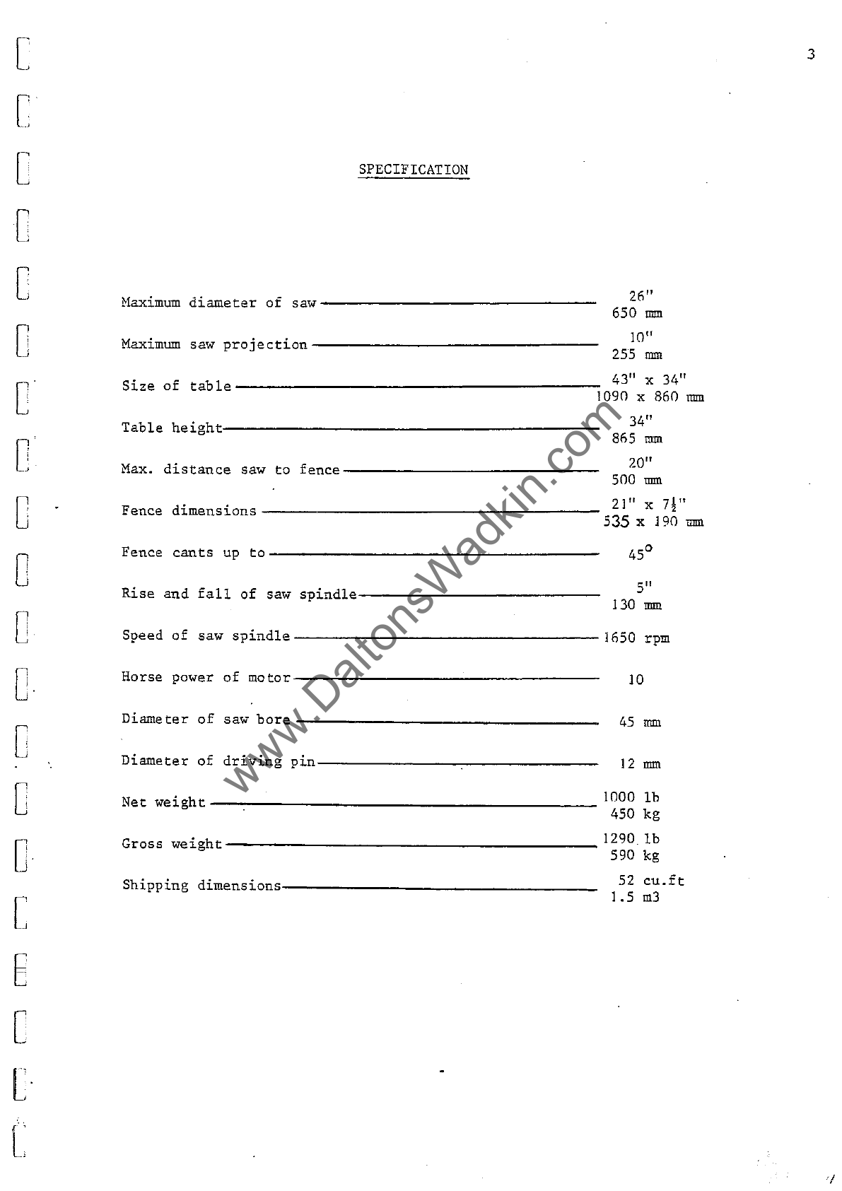
SPECIFICATION
Haximum
diameter
of
saw
-----------------
Maximum
saw
projection----------------------------
26"
650
rmn
10"
255
rmn
43" x 34"
Size
of
table--------------------ll090
x 860
nun
Table
height:-------------------------------------------
Hax.
distance
saw
to
fence--------------------------------
34"
865
rmn
20"
SOO
rmn
21"
X
7~1t
Fence
dimensions---------------------------------------
S35 x 190
rmn
Fence
cants
up
to----------------------------------
Rise
and
fall
of
saw
spindle------------------------------
4S
o
S"
130
rmn
Speed
of
saw
spindle---
__________________
16S0
rpm
Horse
power
of
motor-------------------------------------
Diameter
of
saw bore ____________________________________
Diameter
of
driving
pin--------
_______
~----------------
Net
weight----~---------------------------------------
10
45
rmn
12
rmn
1000
lb
4S0
kg
_
_________________________________
12901b
Gross
weight
590 kg
Shipping
dimensions--------
_____________________________ 52
cu.ft
1.5
m3
3