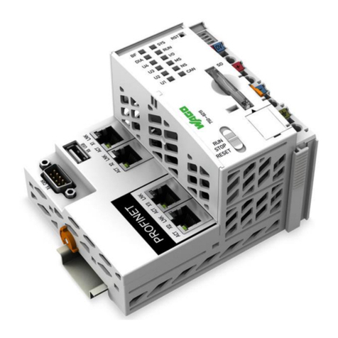
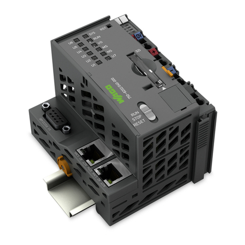
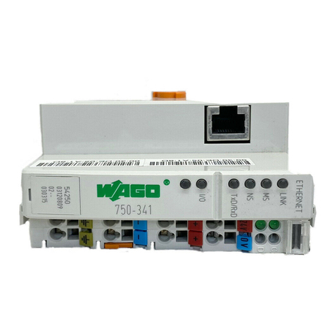
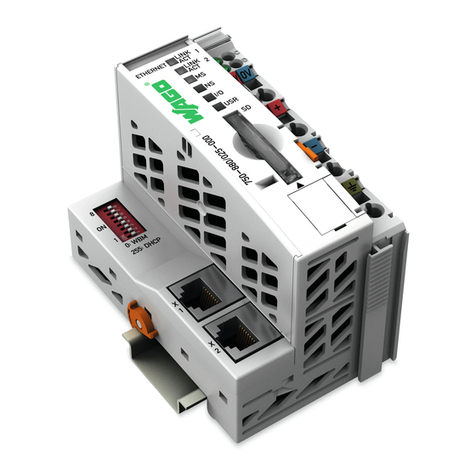
WAGO 750-636/000-700 User manual

Pos:2/Dokumentationallgemein/Einband/EinbandHandbuch- F ro nts ei t e 2015 - mit DocV ari abl e n (Sta nd ar d)@ 9\mod_1285229289866_0.docx@ 64941 @ @ 1
WAGO-I/O-SYSTEM 750
Manual
750-636/000-x00(/xxx-xxx)
DC Drive Controller 24V/5A
DC Drive Controller 24 V / 5 A
Version 2.1.0
Pos: 3 /Al le S eri en ( All g em ei ne M od ul e) /Rec htl ic h es , Al l ge mei n es /I mpr e ss um für Sta nd ard h an dbüc h er - al lg . A ng a be n, Ansc hri ft en, T elef o nn u m mer n und E-Mail -Adres se n @ 3\mod_1219151118203_21.docx @ 21060 @ @ 1

2 WAGO-I/O-SYSTEM 750
750-636/000-x00 DC Drive Controller 24V/5A
Manual
Version 2.1.0
© 2017 WAGO Kontakttechnik GmbH & Co. KG
All rights reserved.
WAGO Kontakttechnik GmbH & Co. KG
Hansastraße 27
D-32423 Minden
Phone: +49 (0) 571/8 87 – 0
Fax: +49 (0) 571/8 87 – 1 69
E-Mail: [email protected]om
Web: http://www.wago.com
Technical Support
Phone: +49 (0) 571/8 87 – 5 55
Fax: +49 (0) 571/8 87 – 85 55
E-Mail: [email protected]om
Every conceivable measure has been taken to ensure the accuracy and
completeness of this documentation. However, as errors can never be fully
excluded, we always appreciate any information or suggestions for improving the
documentation.
E-Mail: documentation@wago.com
We wish to point out that the software and hardware terms as well as the
trademarks of companies used and/or mentioned in the present manual are
generally protected by trademark or patent.
WAGO is a registered trademark of WAGO Verwaltungsgesellschaft mbH.
=== Ende d er Lis t e f ür Textmarke Einband_vorne===

WAGO-I/O-SYSTEM 750 Table of Contents 3
750-636/000-x00 DC Drive Controller 24V/5A
Manual
Version 2.1.0
Pos: 5 /D o ku ment ati on allg e mei n /Ver zei c hni ss e/I nh alt s verz ei ch nis - Ü b er schr if t oG und Ver zei ch nis @ 3\mod_1219151230875_21.docx@21063 @ @ 1
Table of Contents
1Notes about this Documentation................................................................. 6
1.1 Validity of this Documentation................................................................. 6
1.2 Copyright................................................................................................... 6
1.3 Symbols..................................................................................................... 7
1.4 Number Notation....................................................................................... 9
1.5 Font Conventions ...................................................................................... 9
2Important Notes ......................................................................................... 10
2.1 Legal Bases ............................................................................................. 10
2.1.1 Subject to Changes ............................................................................. 10
2.1.2 Personnel Qualifications..................................................................... 10
2.1.3 Use of the WAGO-I/O-SYSTEM 750 in Compliance with Underlying
Provisions ........................................................................................... 10
2.1.4 Technical Condition of Specified Devices ......................................... 11
2.2 Safety Advice (Precautions).................................................................... 12
3Device Description ..................................................................................... 14
3.1 View ........................................................................................................ 16
3.2 Connectors............................................................................................... 17
3.2.1 Data Contacts/Internal Bus................................................................. 17
3.2.2 Power Jumper Contacts/Field Supply ................................................ 18
3.2.3 CAGE CLAMP®Connectors ............................................................. 20
3.3 Display Elements .................................................................................... 21
3.4 Schematic Diagram ................................................................................. 22
3.5 Technical Data ........................................................................................ 23
3.5.1 Device Data ........................................................................................ 23
3.5.2 Power Supply...................................................................................... 23
3.5.3 Communication .................................................................................. 23
3.5.4 Digital Inputs ...................................................................................... 24
3.5.5 Encoder Inputs.................................................................................... 24
3.5.6 Outputs ............................................................................................... 24
3.5.7 Connection Type ................................................................................ 26
3.5.8 Climatic Environmental Conditions................................................... 26
3.6 Standards and Guidelines........................................................................ 27
4Function Description ................................................................................. 28
4.1 Operating Modes and Drive Functions ................................................... 28
4.2 Preset Functions ...................................................................................... 28
4.2.1 Hardware Preset.................................................................................. 28
4.2.2 Software Preset................................................................................... 28
4.3 Brake Functions ...................................................................................... 29
4.4 Stop Functions......................................................................................... 29
4.5 Protective Functions................................................................................ 29
4.6 Operating Modes for Positioning ............................................................ 30
4.7 Prestop..................................................................................................... 31
4.8 Base Mode............................................................................................... 31
4.9 Auto Mode .............................................................................................. 32
4.9.1 Positioning with Activated Optimization ........................................... 33

4 Table of Contents WAGO-I/O-SYSTEM 750
750-636/000-x00 DC Drive Controller 24V/5A
Manual
Version 2.1.0
4.9.2 Positioning with Enabled Optimization and Retry Not Equal to 0
(Loop Traverse) .................................................................................. 34
4.9.3 Positioning with Enabled Optimization and too Short Distance........ 35
4.9.4 Positioning with Negatively Initialized Overtravel............................ 36
4.9.5 Positioning with Positively Initialized Overtravel ............................. 37
4.9.6 Positioning with Negatively Initialized Overtravel at Too Little
Distance .............................................................................................. 38
4.10 Setpoint Change on the Fly ..................................................................... 39
4.11 PWM Control during Positioning ........................................................... 40
4.11.1 General ............................................................................................... 40
4.11.2 Drive Versions Including Change to Lower Speed............................ 41
4.12 Swing-Back Drives with Subsequent Setpoint Position Drive ............... 45
4.12.1 Definition of the Swing-Back Drives ................................................. 45
4.12.2 Calculating the Acceleration Distance ............................................... 46
4.12.3 Calculating a Swing-Back Drive ........................................................ 47
4.13 Standstill Condition................................................................................. 48
4.14 Maximum Pulse Frequency of the Incremental Encoder ........................ 50
5Mounting..................................................................................................... 51
5.1 Mounting Sequence................................................................................. 51
5.2 Inserting and Removing Devices ............................................................ 52
5.2.1 Inserting the I/O Module .................................................................... 52
5.2.2 Removing the I/O Module.................................................................. 53
6Connect Devices ......................................................................................... 54
6.1 Connecting a Conductor to the CAGE CLAMP®................................... 54
7Process Image ............................................................................................. 55
7.1 Overview ................................................................................................. 55
7.2 Control Bytes and Status Bytes............................................................... 56
7.3 Extended Status Bytes............................................................................. 60
7.4 Process Image for Register Communication........................................... 61
8Parameterizing ........................................................................................... 63
8.1 Register Communication......................................................................... 63
8.2 Parameter Records .................................................................................. 66
8.2.1 Available Parameter Records ............................................................. 66
8.2.1.1 Actual (1) ....................................................................................... 66
8.2.1.2 User Settings (2) ............................................................................ 66
8.2.1.3 Factory Default (3) ........................................................................ 66
8.2.2 Password Protection ........................................................................... 67
8.2.3 Changing the Parameter Data Sets ..................................................... 67
8.2.3.1 Actual (1) ....................................................................................... 67
8.2.3.2 User Settings (2) ............................................................................ 68
8.2.3.3 Factory Default (3) ........................................................................ 68
8.2.4 Transfer of the Parameter Data Sets ................................................... 68
8.2.4.1 Request/Response Mechanism ...................................................... 68
8.2.4.2 Session Counter ............................................................................. 68
8.2.4.3 Command Overview...................................................................... 69
8.3 Parameter Channel .................................................................................. 70
8.3.1 Parameter Data (Register 56) ............................................................. 70
8.3.2 Communication Control (Register 57) ............................................... 70
WAGO-I/O-SYSTEM 750 Table of Contents 5
750-636/000-x00 DC Drive Controller 24V/5A
Manual
Version 2.1.0
8.4 Process of Parameter Transmission ........................................................ 72
8.5 General Parameter Data (System Parameter Range)............................... 73
8.6 I/O Module-Specific Parameter Data...................................................... 74
8.6.1 RampTime_START, RampTime_STOP............................................ 75
8.6.2 Prestop_Pos ........................................................................................ 76
8.6.3 Prestop_Neg ....................................................................................... 76
8.6.4 Target_Window.................................................................................. 76
8.6.5 Standstill_Limit, EnginePowerSupply, Positioning_Retry,
Z_Input_Enable, Stop-Mode_PwrUp................................................. 77
8.6.6 PresetValue......................................................................................... 78
8.6.7 Overtravel ........................................................................................... 78
8.6.8 TriggerMode_Inputs, Stop-Mode, DirectionReversal_Delay ............ 79
8.6.9 Filter_Time ......................................................................................... 80
8.6.10 ShutDown_Distance ........................................................................... 81
8.6.11 CurrentLimit_PWM, CurrentControl_PWM ..................................... 82
8.6.12 CurrentLimit_Time, MotionDetectionTimeout.................................. 83
8.6.13 Brake-Mode, Stop-Mode_Entry, Encoder_Limit_Frequency............ 84
8.6.14 Increase_Swing_Back ........................................................................ 85
8.6.15 Extended_Infos................................................................................... 86
8.6.16 Swing_Back_Distance........................................................................ 87
9Using Interference-Free Variations of I/O Modules in Safety Related
Applications................................................................................................ 88
9.1 Important Notes....................................................................................... 89
9.2 Connecting the I/O Module to Safety Switching Devices or
F I/O Modules ......................................................................................... 90
9.2.1 General Structure................................................................................ 90
9.2.2 Example of Connection ...................................................................... 91
List of Figures ...................................................................................................... 92
List of Tables........................................................................................................ 94
=== En de der Lis te für T extmar ke Verz eich nis_vor ne == =

6 Notes about this Documentation WAGO-I/O-SYSTEM 750
750-636/000-x00 DC Drive Controller 24V/5A
Manual
Version 2.1.0
Pos: 7 / All e S eri e n ( All ge mei n e M od ul e) /Üb ers c hri ft en/ Ebe n e 1/H in w eis e z u dies er D o ku me nt ati on - Ü ber sc hr ift 1 @ 4\mod_1237987661750_21.docx@ 29029@ 1 @ 1
1 Notes about this Documentation
Pos: 8 /Al le S eri en ( Allg em ein e Mod ul e)/Si cher h eits- unds onstige Hinweise/Hinweis/Hinweis:Dokumentationaufbewahren@ 4\mod_1237987339812_21.docx @ 29026@ @ 1
Always retain this documentation!
This documentation is part of the product. Therefore, retain the documentation
during the entire service life of the product. Pass on the documentation to any
subsequent user. In addition, ensure that any supplement to this documentation is
included, if necessary.
Pos: 9 /Al le S eri en ( Allg em ein e Mod ul e)/Ü ber schr ift en/ Ebe ne 2/ Gül tig kei tsber eic h - Üb ers c hri ft 2 @ 1 2\mod_1338912448776_21.docx@ 96469@ 2 @ 1
1.1 Validity of this Documentation
Pos: 10 /S er ie 75 0 ( WA GO -I/O-S YS T EM )/H i n weis e z ur D o kum ent at i on/ G ül tig kei ts b er eic h/G ült ig keitsbereichDokumentationI/O-Modulohne Variable (750-636/000-70 0 und /00 0-800) @ 18 \mod_1392650197698_21.docx@ 145698@ @ 1
This document is only valid for the I/O modules listed in the table that are
designated as 750-636/000-x00 below.
Pos: 11 /S erie 750 (WAGO-I/O-SYST EM )/H i n weis e z ur D o kum ent at i on/ G ül tig kei ts b er eic h/ Vari a nt e nli st en/ V ar ia nt enl ist e - 7 50-xxx - Standardversion undVariante/000-800,/000-700 @ 18\mod_1391506931623_21.docx@ 144291@ @ 1
Table 1: Variants
Item Number/Variant
Designation
750-636/000-700
DC Drive Controller 24V/5A/UA
750-636/000-800
DC Drive Controller 24V/5A/R
Pos: 12 /A ll e Ser i en ( All ge mei ne M od ule) / Sich er heits - und sons t ig e H i n weis e/H i n weis /H in wei s: Gül ti g keit der Ang a ben für aufg el ist et e V ar ia nt en @ 9\mod_1281520778141_21.docx @ 63085@ @ 1
Documentation Validity for Variants
Unless otherwise indicated, the information given in this documentation applies to
listed variants.
Pos: 13 /S er ie 75 0 ( WA GO -I/O-S YST EM )/H i nwei se z ur D o kum ent ati on/H i nw eise /Ac ht ung : H in wei s z ur D o ku ment ati on I/O-M odul e 750-xxxx @ 4\mod_1237986979656_21.docx@ 29023@ @1
The I/O module 750-636/000-x00 shall only be installed and operated according
to the instructions in this manual and in the manual for the used fieldbus
coupler/controller.
Consider power layout of the WAGO-I/O-SYSTEM 750!
In addition to these operating instructions, you will also need the manual for the
used fieldbus coupler/controller, which can be downloaded at www.wago.com.
There, you can obtain important information including information on electrical
isolation, system power and supply specifications.
Pos: 14.1 /All e Seri en ( Al lg emei ne M o dul e)/Ü ber sc hri fte n/ Ebe ne 2/Ur h eber sc hutz - Über sc hr ift 2 @ 23\mod_1435647042188_21.docx @ 184808@ 2@ 1
1.2 Copyright
Pos: 14.2 /All e Seri en ( Al lg emei ne Mo d ule) /R ec htli ch es , A llg e mei nes /U rh eb ersc hu tz aus führ li ch @ 4\mod_1235565145234_21.docx@ 27691@ @ 1
This Manual, including all figures and illustrations, is copyright-protected. Any
further use of this Manual by third parties that violate pertinent copyright
provisions is prohibited. Reproduction, translation, electronic and phototechnical
filing/archiving (e.g., photocopying) as well as any amendments require the
written consent of WAGO Kontakttechnik GmbH & Co. KG, Minden, Germany.
Non-observance will involve the right to assert damage claims.
Pos:14.3/Dokumentati on allg e mei n/ Gl i eder ung s el em en te /---Sei t e nwe chs el --- @ 3\mod_1221108045078_0.docx@ 21810 @ @ 1

WAGO-I/O-SYSTEM 750 Notes about this Documentation 7
750-636/000-x00 DC Drive Controller 24V/5A
Manual
Version 2.1.0
Pos: 14.4 /All e Seri en ( Al lg emei ne M o dul e)/Ü ber sc hri fte n/ Ebe ne 2/S ymbol e - Ü b ers chr if t 2 @ 13\mod_1351068042408_21.docx @ 105270@ 2 @ 1
1.3 Symbols
Pos: 14.5 .1 /All e Serie n( Allg emeine M odul e)/Si cherh eits- und sons t ig e Hi n weis e/ Ge fa hr /G ef a hr: _War nu ng vor P er s on en sch ä de n allg e mei n _ - Er läu ter ung @ 13 \mod_1343309450020_21.docx@ 101029@ @ 1
Personal Injury!
Indicates a high-risk, imminently hazardous situation which, if not avoided, will
result in death or serious injury.
Pos: 14 .5.2 /Al le Seri en (All gemei ne Mod ule)/ Sicher heits- u nd sons ti g e Hi n weis e/ Ge fahr /G ef a hr: _War nu ng vor P er s onen sc hä de n d urc h el e ktri sc he n S tro m_ - Er l äut er u ng @ 13\mod_1343309694914_21.docx@ 101030@ @ 1
Personal Injury Caused by Electric Current!
Indicates a high-risk, imminently hazardous situation which, if not avoided, will
result in death or serious injury.
Pos: 14 .5.3 /Al le Seri en (All gemei ne Mod ule)/ Si ch erh ei ts- u nd sons ti ge H i n weis e/ War n ung/ W arn ung : _ W arn u ng vor P ers one nsc h äd en allg em ei n_ - Erläuterung@ 13\mod_1343309877041_21.docx@ 101035 @ @ 1
Personal Injury!
Indicates a moderate-risk, potentially hazardous situation which, if not avoided,
could result in death or serious injury.
Pos: 14 .5.4 /Al le Seri en (All gemei ne Mod ule)/ Sicher heits- u nd sons ti g e Hi n weis e/ Vors ic ht /V ors ic ht: _War n ung vor Per s one nsc hä d en al lg em ein _ - Erläuterung@ 13\mod_1343310028762_21.docx@ 101038@ @ 1
Personal Injury!
Indicates a low-risk, potentially hazardous situation which, if not avoided, may
result in minor or moderate injury.
Pos: 14 .5.5 /Al le Seri en (All gemei ne Mod ule)/ Sicher heits- und sonstigeHinweise/Achtung/Achtung:_Warnung vor Sac hsc h äden allg e mei n_ - Erläuterung@ 13\mod_1343310134623_21.docx@ 101041@ @ 1
Damage to Property!
Indicates a potentially hazardous situation which, if not avoided, may result in
damage to property.
Pos: 14 .5.6 /Al le Seri en (All gemei ne Mod ule)/ Si ch erh ei ts- u nd sons ti ge H i n weis e/ Ac htu ng/ Ac htu ng : _ War nu ng vor Sac hsc h äden dur c h el ek tros t atis c he Aufl adu ng _ - Er l äut er ung @ 13\mod_1343310227702_21.docx@ 101044@ @ 1
Damage to Property Caused by Electrostatic Discharge (ESD)!
Indicates a potentially hazardous situation which, if not avoided, may result in
damage to property.
Pos: 14 .5.7 /Al le Seri en (All gemei ne Mod ule)/ Sicher heits- u nd sonstige Hi nweise/Hinweis/Hinweis:_Wichtiger Hin weis allgemein_- Erläuterung @ 13\mod_1343310326906_21.d ocx @ 10104 7 @ @ 1
Important Note!
Indicates a potential malfunction which, if not avoided, however, will not result in
damage to property.
Pos: 14 .5.8 /Al le Seri en (All gemei ne Mod ule)/ Sicher heits- u nd sons tig e H i n weis e/I nf or ma tio n/I nf or ma tio n: _W ei ter e I nf or ma ti o n al lg e mei n_ - Erl äu ter ung @ 13 \mod_1343310439814_21.docx@ 101051@ @ 1

8 Notes about this Documentation WAGO-I/O-SYSTEM 750
750-636/000-x00 DC Drive Controller 24V/5A
Manual
Version 2.1.0
Additional Information:
Refers to additional information which is not an integral part of this
documentation (e.g., the Internet).
Pos: 14.6 /Dokumentationallgemein/Gliederungselemente/---Seiten wec hs el --- @ 3\mod_1221108045078_0.docx@ 21810 @ @ 1

WAGO-I/O-SYSTEM 750 Notes about this Documentation 9
750-636/000-x00 DC Drive Controller 24V/5A
Manual
Version 2.1.0
Pos: 14.7 /All e Seri en ( Al lg emei ne M o dul e)/Ü ber sc hri fte n/ Ebe ne 2/Dar st ell ung der Z a hle ns yst em e - Ü bers c hri ft 2 @ 23\mod_1435647128078_21.docx @ 18 4811 @ 2 @ 1
1.4 Number Notation
Pos: 14.8 /All e Seri en ( Al lg emei ne Mo d ule) /R ec htli ch es , A llg e mei nes /Z ahl ens y st e me @ 3\mod_1221059454015_21.docx@ 21711@ @ 1
Table 2: Number Notation
Number Code
Example
Note
Decimal
100
Normal notation
Hexadecimal
0x64
C notation
Binary
'100'
'0110.0100'
In quotation marks, nibble separated with
dots (.)
Pos: 14.9 /All e Seri en ( Al lg emei ne M o dul e)/Ü ber sc hri fte n/ Ebe ne 2/Sc hri ft ko nvent i one n - Ü ber sc hri ft 2 @ 23\mod_1435647186005_21.docx@ 184814@ 2@ 1
1.5 Font Conventions
Pos: 14.1 0 / All e Seri e n ( Al lg e m ein e M o dul e) /R e ch tl ich es , A ll ge m ein es / Sc hr ift k onv e nti on en @ 3 \mod_1221059521437_21.docx@ 21714@ @1
Table 3: Font Conventions
Font Type
Indicates
italic
Names of paths and data files are marked in italic-type.
e.g.: C:\Program Files\WAGO Software
Menu
Menu items are marked in bold letters.
e.g.: Save
>
A greater-than sign between two names means the selection of a
menu item from a menu.
e.g.: File > New
Input
Designation of input or optional fields are marked in bold letters,
e.g.: Start of measurement range
“Value”
Input or selective values are marked in inverted commas.
e.g.: Enter the value “4 mA” under Start of measurement range.
[Button]
Pushbuttons in dialog boxes are marked with bold letters in square
brackets.
e.g.: [Input]
[Key]
Keys are marked with bold letters in square brackets.
e.g.: [F5]
Pos: 15 /D o ku me nt ati o n al lg e mei n/ Gl ie der ung s ele m e nte /---Seit e n we chs el --- @ 3\mod_1221108045078 _0.doc x@ 2 1810 @ @1

10 Important Notes WAGO-I/O-SYSTEM 750
750-636/000-x00 DC Drive Controller 24V/5A
Manual
Version 2.1.0
Pos: 16 /A ll e Ser i en ( All ge mei ne M od ule) /Ü b ersc hrif te n/ Ebe ne 1/ Wic hti ge Erl äu ter ung en - Ü ber sc hr ift 1 @ 4 \mod_1241428899156_21.docx @ 32170@ 1 @ 1
2 Important Notes
Pos: 17.1 /All e Seri en ( Al lg emei ne M o dul e)/R ec htl ich es , All ge m ei nes/ Wic htig e Er l äut er ung en - Ei nlei t u ng @ 3\mod_1221059818031_21.docx@ 21717@ @ 1
This section includes an overall summary of the most important safety
requirements and notes that are mentioned in each individual section. To protect
your health and prevent damage to devices as well, it is imperative to read and
carefully follow the safety guidelines.
Pos: 17 .2 /All e Seri en( Allg emeine M odul e)/Ü berschr ifte n/Ebe ne 2/Rec htlic he Gr undlag en - Über sc hr ift 2 @ 3\mod_1221060626343_21.docx@ 21726@ 2 @ 1
2.1 Legal Bases
Pos: 17.3 /All e Seri en ( Al lg emei ne Mo d ule) /R ec htli ch es , A llg e mei nes /Ä nd er ung s vorb eh alt - Üb erschr ift 3 und In halt @ 3\mod_1221060036484_21.docx@ 21720 @ 3 @ 1
2.1.1 Subject to Changes
WAGO Kontakttechnik GmbH & Co. KG reserves the right to provide for any
alterations or modifications. WAGO Kontakttechnik GmbH & Co. KG owns all
rights arising from the granting of patents or from the legal protection of utility
patents. Third-party products are always mentioned without any reference to
patent rights. Thus, the existence of such rights cannot be excluded.
Pos:17.4/Serie750(WAGO-I/O-S YST EM )/ Wi c hti g e Er lä ut er u ng en/ Per s on al q ual if i kat io n/ Per s o nalq u ali fi k ati on 750- xxxx - Ü bers chrift 3 un dI nhalt @ 3\mod_1224061208046_21.docx @ 24063@ 3@ 1
2.1.2 Personnel Qualifications
All sequences implemented on WAGO-I/O-SYSTEM 750 devices may only be
carried out by electrical specialists with sufficient knowledge in automation. The
specialists must be familiar with the current norms and guidelines for the devices
and automated environments.
All changes to the coupler or controller should always be carried out by qualified
personnel with sufficient skills in PLC programming.
Pos:17.5/Serie750(WAGO-I/O-S YST EM )/ Wi c hti g e Er lä ut er u ng en/ Bes ti mm u ng sg e mäß e V er we nd ung / B esti mmungsgemäßeVerwendung750-xxxx - Ü bersc hrift 3 und In halt @ 3\mod_1224064151234_21.docx@ 24070@ 3 @ 1
2.1.3 Use of the WAGO-I/O-SYSTEM 750 in Compliance with
Underlying Provisions
Fieldbus couplers, fieldbus controllers and I/O modules found in the modular
WAGO-I/O-SYSTEM 750 receive digital and analog signals from sensors and
transmit them to actuators or higher-level control systems. Using programmable
controllers, the signals can also be (pre-) processed.
The devices have been developed for use in an environment that meets the IP20
protection class criteria. Protection against finger injury and solid impurities up to
12.5 mm diameter is assured; protection against water damage is not ensured.
Unless otherwise specified, operation of the devices in wet and dusty
environments is prohibited.
Operating the WAGO-I/O-SYSTEM 750 devices in home applications without
further measures is only permitted if they meet the emission limits (emissions of
interference) according to EN 61000-6-3. You will find the relevant information
in the section “Device Description” > “Standards and Guidelines” in the manual
for the used fieldbus coupler/controller.
Appropriate housing (per 2014/34/EU) is required when operating the WAGO-
I/O-SYSTEM 750 in hazardous environments. Please note that a prototype test

WAGO-I/O-SYSTEM 750 Important Notes 11
750-636/000-x00 DC Drive Controller 24V/5A
Manual
Version 2.1.0
certificate must be obtained that confirms the correct installation of the system in
a housing or switch cabinet.
Pos: 17.6 /All e Seri en ( Al lg emei ne Mo d ule) /R ec htli ch es , A llg e mei nes /T ec hni sc her Z us t and der Ger ät e - Ü bersc hrift 3 und I nh al t @ 3\mod_1221060446109_21.docx@ 21723@ 3 @ 1
2.1.4 Technical Condition of Specified Devices
The devices to be supplied ex works are equipped with hardware and software
configurations, which meet the individual application requirements. WAGO
Kontakttechnik GmbH & Co. KG will be exempted from any liability in case of
changes in hardware or software as well as to non-compliant usage of devices.
Please send your request for modified and new hardware or software
configurations directly to WAGO Kontakttechnik GmbH & Co. KG.
Pos:17.7/Dokumentationallgemein/Gliederungselemente/---Seite nwe chs el--- @ 3\mod_1221108045078_0.docx @ 21810 @ @ 1

12 Important Notes WAGO-I/O-SYSTEM 750
750-636/000-x00 DC Drive Controller 24V/5A
Manual
Version 2.1.0
Pos: 17.8 /All e Seri en ( Al lg emei ne M o dul e)/Ü ber sc hri fte n/ Ebe ne 2/Si cher hei t shi nwei s e - Üb ers c hri ft 2 @ 6 \mod_1260180299987_21.docx@ 46724@ 2 @ 1
2.2 Safety Advice (Precautions)
Pos: 17.9 /All e Seri en ( Al lg emei ne M o dul e)/ Sich er hei ts- u nd s ons ti ge H i n weis e/ Einl ei t ung Sich er hei ts hin wei s e H ar d war e @ 6\mod_1260180170493_21.docx@ 46720@ @ 1
For installing and operating purposes of the relevant device to your system the
following safety precautions shall be observed:
Pos: 17.1 0.1 / All e S eri en (Al lg em eine M o dul e)/Si ch erh eits- un d s o nsti g e H in w eis e /G ef a hr/G ef ahr : Nic ht an G er ät e n un ter S pa nnu ng ar bei te n! @ 6\mod_1260180365327_21.docx @ 46727 @ @ 1
Do not work on devices while energized!
All power sources to the device shall be switched off prior to performing any
installation, repair or maintenance work.
Pos: 17.1 0. 2 / S eri e 750 ( W AG O-I/O-SY ST EM)/ Wic htig e Erl äu ter ung en/Si c herhei ts - und s o nsti g e H i n wei se /G ef ahr / Ge fa hr : E i nb au 0 7 50-xx xx nur i n Geh äus en, Sc hrä n ken o der el e ktris c hen Betr ie bsr ä ume n! @ 6\mod_1260180556692_21.docx @ 46731@ @ 1
Install the device only in appropriate housings, cabinets or in electrical
operation rooms!
The WAGO-I/O-SYSTEM 750 and its components are an open system. As such,
install the system and its components exclusively in appropriate housings,
cabinets or in electrical operation rooms. Allow access to such equipment and
fixtures to authorized, qualified staff only by means of specific keys or tools.
Pos: 17.1 0.3 / All e S eri en (Al lg em eine M o dul e)/Si ch erh eits- un d s o nsti g e H in w eis e /G ef a hr/G ef ahr : Unf all ver h üt ungs vor sc hr i ft en b e ach te n! @ 6\mod_1260180657000_21.docx@ 46735 @ @ 1
Pos: 17.1 0.4 / All e S eri en (Al lg em eine M o dul e)/Si ch erh eits- un d s o nsti g e H in w eis e /G ef a hr/G ef ahr : Auf nor mg er ec ht e n A ns c hl us s acht en! @ 6\mod_1260180753479_21.docx@ 46739@ @ 1
Pos: 17.1 1.1 / All e S eri en (Al lg em eine M o dul e)/Si ch erh eits- un d s o nsti g e H in w eis e /A cht u ng /Ac ht u ng : D ef e kte oder bes ch ädi gt e Ger ät e austa us c h en! @ 6\mod_1260180857358_21.docx@ 46743 @ @ 1
Replace defective or damaged devices!
Replace defective or damaged device/module (e.g., in the event of deformed
contacts), since the long-term functionality of device/module involved can no
longer be ensured.
Pos: 17.1 1.2 / All e S eri en (Al lg em eine M o dul e)/Si ch erh eits- und sonstigeHinweise/Achtung/Achtung:Gerätevor kriechendenundisolierendenStoffenschützen!@ 6\mod_1260181036216_21.docx@ 46747@ @ 1
Protect the components against materials having seeping and insulating
properties!
The components are not resistant to materials having seeping and insulating
properties such as: aerosols, silicones and triglycerides (found in some hand
creams). If you cannot exclude that such materials will appear in the component
environment, then install the components in an enclosure being resistant to the
above-mentioned materials. Clean tools and materials are imperative for handling
devices/modules.
Pos: 17.1 1.3 / All e S eri en (Al lg em eine M o dul e)/Si ch erh eits- unds onstigeHinweise/Achtung/Achtung:R einig u ng n ur mit zul ässig e n M at eri alie n! @ 6\mod_1260181203293_21.docx@ 46751@ @ 1
Clean only with permitted materials!
Clean soiled contacts using oil-free compressed air or with ethyl alcohol and
leather cloths.
Pos: 17.1 1.4 / All e S eri en (Al lg em eine M o dul e)/Si ch erh eits- unds onstigeHinweise/Achtung/Achtung:KeinKontaktspray verwenden! @ 6\mod_1260181290808_21.docx@ 46755@ @ 1

WAGO-I/O-SYSTEM 750 Important Notes 13
750-636/000-x00 DC Drive Controller 24V/5A
Manual
Version 2.1.0
Do not use any contact spray!
Do not use any contact spray. The spray may impair contact area functionality in
connection with contamination.
Pos: 17.1 1.5 / All e S eri en (Al lg em eine M o dul e)/Si ch erh eits- un d s o nst ig e Hin w eis e /A cht u ng /Ac ht u ng : V er pol ung en der Dat en- un d Ver sor g u ng sl eit u ng en ver m eid e n! @ 6\mod_1260184045744_21.docx@ 46767 @ @ 1
Do not reverse the polarity of connection lines!
Avoid reverse polarity of data and power supply lines, as this may damage the
devices involved.
Pos: 17.1 1.6 / All e S eri en (Al lg em eine M o dul e)/Si ch erh eits- unds onstige Hinweise/Achtung/Achtung:Elektrostatische Entla dung ver mei de n! @ 6\mod_1260181364729_21.docx@ 46759@ @ 1
Avoid electrostatic discharge!
The devices are equipped with electronic components that may be destroyed by
electrostatic discharge when touched. Please observe the safety precautions
against electrostatic discharge per DIN EN 61340-5-1/-3. When handling the
devices, please ensure that environmental factors (personnel, work space and
packaging) are properly grounded.
Pos: 18 /D oku ment ation all g emei n/ Gli e der ung s el e me nte /---Sei t e n wechs el--- @ 3\mod_1221108045078_0.docx@ 21810@ @ 1

14 Device Description WAGO-I/O-SYSTEM 750
750-636/000-x00 DC Drive Controller 24V/5A
Manual
Version 2.1.0
Pos: 19 /Al l e Seri en (All g emei n e M o d ule) /Ü b er schr i f te n/ Eb ene 1/G er ät e bes chr eib ung - Ü ber sc hri f t 1 @ 3\mod_1233756084656_21.docx@ 27096@ 1 @ 1
3 Device Description
Pos: 20 .1.1 /S erie 750 ( WAGO -I/O-SYSTEM)/Gerätebeschreibung/Einleitung/Anwendung/SO/Anwendung750-0636 @ 18\mod_1390462206892_21.docx@ 142936@ @ 1
The I/O module 750-636/000-x00 (DC Drive Controller 24V/5A) is used for
controlled positioning of CD collector motors up to 5 A rated current with a
starting current of max. 15 A. The final stage is a short circuit-proof H-bridge
with braking and idle function. In addition, the power electronics are temperature
controlled.
The I/O module can be used as a simple power controller and for simple detection
of incremental encoder signals.
In addition to basic motion commands (MovePos, MoveNeg), automatic
positioning may be optimized for different applications via different functions and
parameters. The motor can be moved by pulse width modulation (PWM) in
addition to start/stop ramps.
Pos: 20 .1.2 /S erie 750 ( WAGO -I/O-SYST EM )/G erä te bes c hrei bu ng/Ei nl ei tu ng/I/ O-B es c hr ei bu ng /S O/ I /O-Bes chr ei bung 7 50-0636/00 0-700_Eingänge @ 18\mod_1391508974823_21.docx@ 144303@ @ 1
The I/O module 750-636/000-x00 (DC Drive Controller 24V/5A) has 3 digital 24
V inputs according to IEC 61131-2 for connecting limit switches (E+ and E-) and
for setting the reference point (P) and 2 other digital inputs to connect an
incremental encoder (A and B).
Pos: 20 .1.3 /S erie 750 ( WAGO -I/O-SYST EM )/G erä te bes c hrei bu ng/Ei nl ei tu ng/I/ O-B es c hr ei bu ng /S O/ I /O-Bes chr ei bung 7 50-0636_Ausgänge@ 18\mod_1390464875971_21.docx@ 142944@ @ 1
A DC motor is attached at outputs A+ and A-.
Pos: 20 .1.4 /S erie 750 ( WAGO -I/O-SYST EM )/G erä te bes c hrei bu ng/Ei nl ei tu ng/I/ O-B es c hr ei bu ng /S O/ I /O-Bes chr ei bung 7 50-0636_Abschaltung Motorausgang@ 18\mod_1390464997463_21.docx@ 143018@ @ 1
The limit switches automatically disable the motor output.
Pos: 20.1 .5 /Dok um en ta tio n al lg e mei n/ Gli eder ung s ele men te /---Le era bs atz-( 2Z)--- @ 3\mod_1224662755687_0.docx @ 24460 @ @ 1
Pos: nul l /Ser ie 750 (W AGO-I/ O-SYST EM) /G erä teb eschr ei bu ng/ Ei nleit u ng/V ers org ung /M otor ver sor gung ss p annu ng U A2 @ 3 0\mod_1501157651135_21.docx@ 456756@ @ 1
The motor supply voltage must be connected separately to the UAconnection.
750-636/000-800 I/O module only:
Switching measures ensure that there is no interference between this and the
other voltage ranges of the I/O module. Motor outputs A+ and A- can be switched
by a safety circuit according to EN IEC 61062 or EN ISO 13849 without reaction
via supply voltage UA of the module.
Pos: 20 .1.7 /S erie 750 ( WAGO -I/O-SYST EM )/G erä te bes c hrei bu ng/Ei nl ei tu ng/I/ O-B es c hr ei bu ng /Al lg e m ein / V er wei s auf Kapi tel "A ns c hl üss e" @ 8\mod_1276775378035_21.docx@ 57956@ @ 1
The assignment of the connections is described in the “Connectors” section.
Pos: 20 .1.8 /S erie 750 ( WAGO -I/O-SYST EM )/G erä te bes c hrei bu ng/Ei nl ei tu ng/I/ O-B es c hr ei bu ng /Al lg e m ein / V er wei s auf Kapi tel "G er ät e ansc hli eß en" > " A nsc hl us s b eis pi el (e) " @ 5\mod_1246015203281_21.docx@ 36298@ @ 1
Connection examples are shown in section “Connect Devices” > … >
“Connection Example(s)”.
Pos: 20 .1.9 /S erie 750 ( WAGO -I/O-SYST EM )/G erä te bes c hrei bu ng/Ei nl ei tu ng/L ED-A nz eig e/ LED Zu st and Sig nal / B etr ie bs ar t/F e hler @ 18\mod_1390469225557_21.docx@ 143022@ @ 1
Four green status LEDs indicate the signal status of the digital inputs and the
status of the power supply. Two yellow LEDs and one red LED indicate the
operating mode and errors.
Pos: 20.1 .1 0 / S eri e 750 ( W AG O-I/O-SY ST EM ) /G erät e be sc hr ei b ung/ E inl eit ung / L ED -Anz eig e /V er weis auf Kapi tel "A nz eig eel e me nt e" @ 5\mod_1246010525000_21.docx@36194 @ @ 1
The meaning of the LEDs is described in the “Display Elements” section.
Pos: 20.1 .1 1 / S eri e 750 ( W AG O-I/O-SY ST EM ) /G erät e be sc hr ei b ung/ E inl eit ung / V er sor gu ng /V er s or gung 24 V, 0 V ü b er Leis t ung s ko nt a kte Stan d ard @ 3\mod_1226498974531_21.docx@ 25020@ @ 1
The I/O module 750-636/000-x00 (DC Drive Controller 24V/5A) receives the
24 V voltage supply for the field level from an upstream I/O module or from the
fieldbus coupler/controller via blade-formed power jumper contacts. It then
provides these potentials to subsequent I/O modules via spring-formed power
jumper contacts.
Pos: 20.1 .1 2 / S eri e 750 ( W AG O-I/O-SY ST EM) /Wic hti g e Erl äut erung en /Sic her hei ts- un d s o nsti g e Hi n wei se /Ac ht ung /Ac ht ung : Maxi m aler Str o m Lei s tu ngs ko nta kt e 1 0 A @ 3\mod_1226499143500_21.docx@ 25029 @ @ 1

WAGO-I/O-SYSTEM 750 Device Description 15
750-636/000-x00 DC Drive Controller 24V/5A
Manual
Version 2.1.0
Do not exceed maximum current via power jumper contacts!
The maximum current to flow through the power jumper contacts is 10 A.
Greater currents can damage the contacts.
When configuring your system, ensure that this current is not exceeded.
If exceeded, insert an additional supply module.
Pos: 20.1 .1 3 / S eri e 750 ( W AG O-I/O-SY ST EM ) /G erät e be sc hr ei b ung/ E inl eit ung / V er sor gu ng /G al vani sc h e Tr e n nung F eld/ S ys te m @ 3\mod_1233756478750_21.docx@ 27102@ @ 1
The field voltage and the system voltage are electrically isolated from each other.
Pos: 20.1 .14 / S erie 750 ( WA GO-I/O-SYSTE M)/Wi cht ig e Erl äu ter ung en/Si cher hei ts- un d s o nst ig e Hi n wei se /W ar nu ng / War nu ng : Eins atz Var i ant e / x xx-8 xx in sic herhei tsger icht eten An wend unge n(o hne V ariabl e 750-636) @ 1 8\mod_1392707215425_21.docx@ 145718@ @ 1
Using in safety related applications!
When using the I/O module 750-636/000-800 in safety-related applications, the
instructions and connection examples in Section “Use in safety-related
applications” are to be observed!
Pos: 20.1 .1 5 / S eri e 750 ( W AG O-I/O-SY ST EM )/G er ät e bes chr eib ung / Ei nl ei t ung/ V er sor g u ng/ A nor d nu ng b ei Ein sat z in si c her heit s ger i ch te te n A nw e nd ung en bloc kw eis e @ 5\mod_1246876694406_21.docx@ 36674@ @ 1
Any configuration of the output modules is possible when designing the fieldbus
node. Grouping of module types is not necessary.
Pos: 20.1 .1 6 / S eri e 750 ( W AG O-I/O-SY ST EM ) /G erät e be sc hr ei b ung/ E inl eit ung / Ei n sa tzb er eic h/ E in sa tz ber ei c h 7 50-x xxx alle Kop pler /C ont roll er oh ne Ei ns chr ä nkung @ 3 \mod_1232541691906_21.docx@ 26522@ @ 1
The I/O module 750-636/000-x00 can be used with all fieldbus
couplers/controllers of the WAGO-I/O-SYSTEM 750.
Pos:20.2/Dokumentationallgemein/Gliederungselemente/---Seite nwe chs el--- @ 3\mod_1221108045078_0.docx @ 21810@ @ 1

16 Device Description WAGO-I/O-SYSTEM 750
750-636/000-x00 DC Drive Controller 24V/5A
Manual
Version 2.1.0
Pos: 20.3 /All e Seri en ( All g e mei ne M o d ule) /Ü bers chr ift e n/ Eb e ne 2/A nsi ch t - Ü ber s chr ift 2 @ 4\mod_1240984217343_21.docx@ 31958@ 2 @ 1
3.1 View
Pos:20.4/Serie750(WAGO-I/O-S YST EM ) / Ger äte b esc hr ei bu ng /A ns i c ht /S on d er kle mm en/ A nsi c ht 750-0636 @ 18\mod_1390475431469_21.docx@ 143224@ @1
Figure 1: View
Pos:20.5/Serie750(WAGO-I/O-S YST EM) / Ger äte b esc hr ei bung /A nsi c ht /A nsic ht C ag eC l amp® _ Leg en de mit LEDs , mit 1 Entr ieg el ung sl asc h e @ 15\mod_1370867188922_21.docx @ 122225@ @ 1
Table 4: Legend for Figure “View”
Pos.
Description
Details See Section
1
Marking possibility with Mini-
WSB
---
2
Status LEDs
“Device Description” > “Display Elements”
3
Data contacts
“Device Description” > “Connectors”
4
CAGE CLAMP®connectors
“Device Description” > “Connectors”
5
Power jumper contacts
“Device Description” > “Connectors”
6
Release tab
“Mounting” > “Inserting and Removing
Devices”
Pos:20.6/Dokumentationallgemein/Gliederungselemente/---Seite nwe chs el--- @ 3\mod_1221108045078_0.docx @ 21810@ @ 1

WAGO-I/O-SYSTEM 750 Device Description 17
750-636/000-x00 DC Drive Controller 24V/5A
Manual
Version 2.1.0
Pos: 20.7 /All e Seri en ( Al lg emei ne M o d ule) /Ü ber s c hri ft e n/ Eb e ne 2/ A ns c hlüs s e - Ü b ers c hri ft 2 @ 4\mod_1240984262656_21.docx@31961 @ 2@ 1
3.2 Connectors
Pos:20.8/Serie750(WAGO-I/O-S YST EM) /Ger äte b esc hrei bu ng/A nsc hl üs se/ Da ten kon tak te/ Kl em men bus - Über sc hr ift 3 @ 6\mod_1256294684083_21.docx@ 43 660 @ 3 @ 1
3.2.1 Data Contacts/Internal Bus
Pos: 20 .9.1 /S erie 750 ( WAGO -I/O-SYSTEM)/Gerätebeschreibung/Anschlüsse/Datenkontakte- F el dbu s kop pler /-c on tr ol ler , A b bil d ung u nd B es c hr ei bu ng @ 3\mod_1231771259187_21.docx @ 26002@ @1
Communication between the fieldbus coupler/controller and the I/O modules as
well as the system supply of the I/O modules is carried out via the internal bus. It
is comprised of 6 data contacts, which are available as self-cleaning gold spring
contacts.
Figure 2: Data Contacts
Pos: 20 .9.2 /S erie 750 ( W AG O-I/ O-SYSTEM)/Wichtige Erläuterungen/Sicherheits- und so nstige H inwei se/A chtung /Ach tung: B uskle mmen nic ht auf Gol dfe derk ontakt e legen! @ 7\mod_1266318463636_21.docx@ 50695@ @ 1
Do not place the I/O modules on the gold spring contacts!
Do not place the I/O modules on the gold spring contacts in order to avoid soiling
or scratching!
Pos: 20 .9.3 /S erie 750 ( WAGO -I/O-SYSTEM)/Wichtige Erläuterungen/Sicherheits- undsonstige Hinweise/Achtung/Achtung:ESD- A uf g ut e E rd ung der Umg eb u ng acht e n! @ 7\mod_1266318538667_21.docx@ 50708 @ @ 1
Ensure that the environment is well grounded!
The devices are equipped with electronic components that may be destroyed by
electrostatic discharge. When handling the devices, ensure that the environment
(persons, workplace and packing) is well grounded. Avoid touching conductive
components, e.g. data contacts.
Pos: 20.1 0 /D o ku ment ati o n all ge mei n/G li ed eru ngsel e me nte/---S ei ten w ec hs el--- @ 3 \mod_1221108045078_0.docx@ 21810@ @ 1

18 Device Description WAGO-I/O-SYSTEM 750
750-636/000-x00 DC Drive Controller 24V/5A
Manual
Version 2.1.0
Pos: 20.1 1 / S eri e 750 ( W AG O-I/ O-SYST EM ) /G erät e be sc hr ei b ung /A ns c hl üss e/ L eis t ung s ko nta kt e/ F eld v ers or g ung - Ü b ers chr if t 3 @ 6 \mod_1256294692864_21.docx@ 43664@ 3 @ 1
3.2.2 Power Jumper Contacts/Field Supply
Pos: 20.1 2. 1 / S eri e 750 ( W AG O-I/O-SY STEM )/Wic htig e Er l äuter ung en /Sic her hei ts - und s o nsti g e H i n w eise /V or si ch t/ Vor si c ht: Ver let z u ngs g ef ahr dur c h s c har f kanti g e M es ser kon ta k t e! @ 6\mod_1256193279401_21.docx@ 43414@ @ 1
Risk of injury due to sharp-edged blade contacts!
The blade contacts are sharp-edged. Handle the I/O module carefully to prevent
injury.
Pos: 20.1 2. 2 / S eri e 750 ( W AG O-I/O-SY ST EM ) /G erät e be sc hr ei b ung/ A ns c hl üss e/ L eis t ung s kon ta kt e 2 L K ( M ess er /F ed er ) - Ei nlei t u ng @ 15\mod_1371721641099_21.docx@ 123714@ @ 1
The I/O module 750-636/000-x00 has 2 self-cleaning power jumper contacts that
supply and transmit power for the field side. The contacts on the left side of the
I/O module are designed as blade contacts and those on the right side as spring
contacts.
Pos: 20.1 2. 3 / S eri e 750 ( W AG O-I/O-SY ST EM ) /G erät e be sc hr ei b ung/ A ns c hl üss e/ L eis t ung s kon ta kt e 2 L K ( M ess er /F ed er ) - A b bi ldu ng , ei nfa ch e Breit e - Standard@ 15\mod_1367500700037_21.docx@ 118396@ @ 1
Figure 3: Power Jumper Contacts
Pos: 20.1 2. 4 / S eri e 750 ( W AG O-I/O-SY ST EM ) /G erät e be sc hr ei b ung/ A ns c hl üss e/ L eis t ung s kon ta kt e 2 L K ( M ess er /F ed er ) - Legende@ 15\mod_1371721352500_21.docx@ 123710@ @1
Table 5: Legend for Figure “Power Jumper Contacts”
Contact
Type
Function
1
Spring contact
Potential transmission (Uv) for field supply
2
Spring contact
Potential transmission (0 V) for field supply
3
Blade contact
Potential feed-in (0 V) for field supply
4
Blade contact
Potential feed-in (Uv) for field supply
Pos: 20.1 2. 5 / S eri e 750 ( W AG O-I/O-SY ST EM)/ Wic htig e Erl äu ter ung en/Si c herhei ts - und s o nsti g e Hi n wei se /Ac ht ung /Ac ht ung : Maxi m aler Str o m Lei s tu ngs ko nt ak te 1 0 A @ 3\mod_1226499143500_21.docx@ 25029 @ @ 1
Do not exceed maximum current via power jumper contacts!
The maximum current to flow through the power jumper contacts is 10 A.
Greater currents can damage the contacts.
When configuring your system, ensure that this current is not exceeded.
If exceeded, insert an additional supply module.
Pos: 20.1 2. 6 / S eri e 750 ( W AG O-I/O-SY ST EM)/ Wic htig e Erl äu ter ung en/Si c herhei ts - und s o nstig e H i nw eise /Hi nw eis /Hi n weis : P ote nti al ein spei s emo dul für E r de ei ns etz en! ( keine LK für Erde) @ 3 \mod_1226499037468_21.docx@ 25023 @ @ 1

WAGO-I/O-SYSTEM 750 Device Description 19
750-636/000-x00 DC Drive Controller 24V/5A
Manual
Version 2.1.0
Use supply modules for ground (earth)!
The I/O module has no power jumper contacts for receiving and transmitting the
earth potential. Use a supply module when an earth potential is needed for the
subsequent I/O modules.
Pos: 20.1 3 /D o ku ment ati o n all ge mei n/G li ed eru ngsel e me nte/---S ei ten w ec hs el--- @ 3 \mod_1221108045078_0.docx@ 21810@ @ 1

20 Device Description WAGO-I/O-SYSTEM 750
750-636/000-x00 DC Drive Controller 24V/5A
Manual
Version 2.1.0
Pos: 20.1 4 / S eri e 750 ( W AG O-I/ O-SYST EM ) /G erät e be sc hr ei b ung /A ns c hl üss e/C AG E C L AM P-A nschlüsse - Ü bers c hri ft 3 @ 6\mod_1256296337770_21.docx@ 43674@ 3 @ 1
3.2.3 CAGE CLAMP®Connectors
Pos: 20.1 5 / S eri e 750 ( W AG O-I/ O-SYST EM ) /G er ät e be sc hr ei b u ng /A nsc hl üss e/ S on d erkl e m me n/ A nsc hl üss e 7 50-06 3 6/ 00 0-700 @ 18\mod_1391512049175_21.docx@ 144348@ @ 1
Figure 4: CAGE CLAMP®Connectors
Table 6: Legend for Figure “CAGE CLAMP®Connectors”
Designation
Connector
Function
E+ 1
Input for positive limit switch
(break/make contact configurable)
E− 5
Input for negative limit switch
(break/make contact configurable)
A 2
Input for the A signal from the magnetic
transmitter (negative switching)
B 6
Input for the B signal from the magnetic
transmitter (negative switching)
P 3
Input for the preset switch
(break/make contact configurable)
UA
7
Connection for motor supply voltage
A+
4
Motor connection +
A−
8
Motor connection −
Pos: 20.1 6 /D o ku ment ati o n all ge mei n/G li ed eru ngsel e me nte/---S ei ten w ec hs el--- @ 3 \mod_1221108045078_0.docx@ 21810@ @ 1
This manual suits for next models
4
Table of contents
Other WAGO Controllers manuals

WAGO
WAGO 750-806 User manual

WAGO
WAGO 750-880 User manual

WAGO
WAGO 8003 Series Product guide

WAGO
WAGO 750-8215 User manual

WAGO
WAGO 750 Series User manual

WAGO
WAGO PFC100 User manual

WAGO
WAGO 750-341 User manual

WAGO
WAGO 750-8202/040-001 User manual

WAGO
WAGO PFC200 2ETH RS XTR User manual

WAGO
WAGO 750-881 Service manual
Popular Controllers manuals by other brands

Newport
Newport Pt32 Operator's manual

Precision Digital Corporation
Precision Digital Corporation PROVU PD6310 instruction manual

Dungs
Dungs GasMultiBloc MB 403 B01 Series instructions

Thermo Scientific
Thermo Scientific ALPHA COND 1000 manual

Mi-Light
Mi-Light FUT092 user manual

FELLER ENGINEERING
FELLER ENGINEERING MCS manual