Warmup USDW360 User manual

110 – 120 Volt
Installation
Manual
IMPORTANT
Read this manual before
attempting to install
your undertile heater.
Incorrect installation
could damage the heater
and will invalidate
your warranty.
TECHNICAL HELPLINE
888-WARMFEET/888-927-6333

2
Contents
3
4
6
7
12
14
15
16
17
18
19
22
23
Before you Start
Do’s and Dont's
Heater information
Preparation & Electric Provision
Sub-floor preparation
Wiring configuration
Installing multiple heaters
Installation step 1
Installation step 2
Sizing Guide
Installation step 3
Installation step 4
Installation step 5
Limited Warranty & SafetyNet
Guarantee
Terms and Conditions
WARMUP UNDERTILE
SPACE HEATING CABLE
FOR INSTALLATION IN
FLOORS.
Your Warmup® Undertile™
Heater has been designed so
that installation is quick and
straight forward. As with all
electrical systems, certain
procedures must be strictly
followed.
Warmup Inc, the manufacturer of the Warmup®
Undertile™ Heating System, accepts no
liability, expressed or implied, for any loss or
consequential damage suffered as a result of
installations which in any way contravene the
instructions that follow.
NA041-USDW-120-0807
24
25

Before you Start
Included with each Warmup heater system purchased should be the following:
• Primer
• Roller (to apply primer)
• Tape
• Installation Manual
• Thermostat
Double check your measurements and ensure you have the right heater size/s for the area
you need to heat. Bear in mind that the heating element should not be installed under
appliances or permanent fixtures and fittings such as refrigerators, washer/dryer, cabinets,
tubs, vanity units etc. Below is a quick reference guide:
110 – 120 VOLT HEATERS
15 - 24 sq ft 1 x USDW360 undertile heater
25 - 34 sq ft 1 x USDW480 undertile heater
35 - 44 sq ft 1 x USDW720 undertile heater
45 - 59 sq ft 1xUSDW950 undertile heater
If you are missing any of the box contents or believe you have the incorrect heater/s to
cover thearea required, please call 888-927-6333 for assistance.
There will be other materials you need to complete the project which are not included
within the heating system. These include:
• Digital ohm multimeter - For space heating cable testing.
• A 4" double gang electrical box (for the thermostat) - with a mud square.
• Tile installation products and tools.
NOTE: Please ensure you do not damage the wire.
Be sure to test the system BEFORE you tile. See pg 16 for
more details.
3

4
Do’s and Dont’s
DO use a qualified installer.
DO check space heating cable with OHM meter.
DO carefully read this installation manual before commencing installation.
DO ensure the floor surface is smooth, clean and dry before priming the
floor with Warmup® primer.
DO ensure good ventilation during application and drying of the thermal
primer.
DO plan theheater layout and installation so that any drilling after tiling
(e.g. for fixtures such as vanity units, tubs) will not damage the wiring.
Remember to keep a copy for future reference.
DO maintain a gap of min. 2”, max. 4” between the space
heating cable runs at all times.
DO protect the space heating cable, including the joint, with cardboard or
hardboard between installation and tiling.
DO protect the space heating cable with cardboard or hardboard between
installation and tiling.
DO use thin set mortars and grouts (latex modified), suitable for use with
underfloor heating (this will be specified in the manufacturers'
instructions).
DO check that theheater is working immediately before commencing tiling.
DO takeparticular carewhen tiling not to dislodge or damage the space
heating cable.
DO ensure that each tile is solidly bedded in tile adhesive, with no gaps or
voids beneath.
DO remember to install the floor probe for the Warmup® thermostat.
DO makesureall electrical work is done by qualified persons in accordance
with local building and electrical codes, the National Electrical Code
(NEC), especially article 424, Part V of the NEC, ANSI/NFPA 70.
DO Call the Warmup Technical Helpline: 888-927-6333 if necessary.
DO ensure that you have electrical provision to run the heating system at
110 – 120 VAC, depending on the system you're installing.
DO remember to attach the ratinglabels included within this manual to the
circuit breaker and thermostatic controls.
DO sketch a diagram of the space heating cable layout, which should be kept
with themanual for future reference.

5
Do’s and Dont’s
DON’T attempt to connect the heaters to any power source prior to
completion of installation.
DON’T install the space heating cable under any built-in items (i.e. tubs,
vanity units, bookshelves, walls or partitions), or under any zero-
clearance, dedicated-location furniture or appliances.
DON’T install the Warmup® Undertile™ Heating System heater under any
floor other than ceramic, quarry or natural stone tiles.
DON’T commence installation on a mud job/screed that has not been
fully cured.
DON’T allow traffic over the primed floor or the installed space heating
cable before tiling.
DON’T shorten the space heating cable at any time.
DON’T allow the space heating cables to cross over or touch each other
at anypoint.
DON’T store tiles, sharp or heavy objects on any of the wiring while
tiling or bang a trowel on the installation area to remove excess
mortar from the trowel.
DON’T commence tiling before testing the Warmup® Undertile™ Heating
System.
DON’T switch on the installed heating system until tile adhesive has fully
cured (1 - 3 weeks minimum), check adhesive manufacturer's
instructions.
DON’T clear grout lines with a utility knife.
DON’T install thespace heating cable on stairways, up walls or in closets.
DON’T attempt to repair thespace heating cable if it becomes damaged.
Call the technical helpline for further instruction:
888 WARMFEET/888-927-6333

Heater information
6
The heaters consist of a fixed length of space heating cable terminated at one
end with 9’ of unheated lead. We recommend you do not alter the length of
the unheated lead, however if necessary, the wire can be extended if a UL-
approved wire and connector box suitable for the purpose is used (e.g.
waterproof if going into the floor, etc.). We recommend you do not alter the
length of the unheated lead, however if necessary, the wire can be extended if
a UL-approved wire and connector box suitable for the purpose is used (e.g.
waterproof if going into the floor, etc). This must be carried out by a qualified
electrician in accordance with local/state laws and guidelines This must be
carried out by a qualified electrician in accordance with local/state laws and
guidelines.
Inspect the entire heater for damage, this includes the factory made joint and
end termination. The joint and end termination cannot be altered or remade if
damaged. If any parts are damaged contact the technical helpline (888-927-
6333).
The core and ground braid are factory joined in a water resistant joint assembly to each supply
con
ductor and ground conductor of the unheated lead. The unheated lead must not be reduced
in length. Excess cable should be securely positioned inside the conduit in the wall.
No of heaters Heater Space Watts @ Watts @ Nominal Nominal Amps Nominal
per 15 amp Model Heating 110Vac 120Vac Cable Length Resistive Resistance
supply point Cable (ft) (@120 volts) (ohms - cold )
Color
5 (13.5amp) USDW360 Grey 300 350 66 2.7 40
4 (14.4amp) USDW480 Red 400 470 99 3.6 30
2 (11.0amp) USDW720 600 720 155 5.5 20
2 (14.6amp) USDW950 800 950 216 7.3 15
Warmup® Undertile™ Heating System is designed for use with
ceramic, quarry or natural stone tiles. Use the Warmup Carbon
Heater for heating under laminate, engineered wood or any other
non-hard surface flooring.
Orange/
Black
Grey/
Black
110 – 120 Volt Heater Information

7
Making electrical provision for the heater
For each Warmup® Heater you install, you will have 1 unheated lead running from the floor to
the thermostat's electric connection. The joint connecting the unheated lead to the space
heating cable must be at least 2 inches from the wall and placed in a position to be covered by
tile and thin set mortar.
It may be necessary to chisel out short channels in the subfloor to minimize the increased
height presented by the floor probe and the unheated lead.
All electrical connections should be done by a qualified technician.
Install to NEC and local BOCA codes.
Separate conduit will be required to run the unheated lead and the sensor wire back up to the
thermostat. Please note that they cannot be placed within the same conduit. Neither the
unheated lead or sensor wire must cross, or come into contact with, the heating element. Bear
in mind that you will need to make provision for drawing the unheated lead and sensor
wire up through the conduit to the control box.
Electrical Requirements
Please refer to the table on page 6 to calculate the amperage load for your particular
system. For smaller areas, you may be able to utilize an existing circuit. In most cases,
however, you will need a separate circuit to power the Warmup heaters.
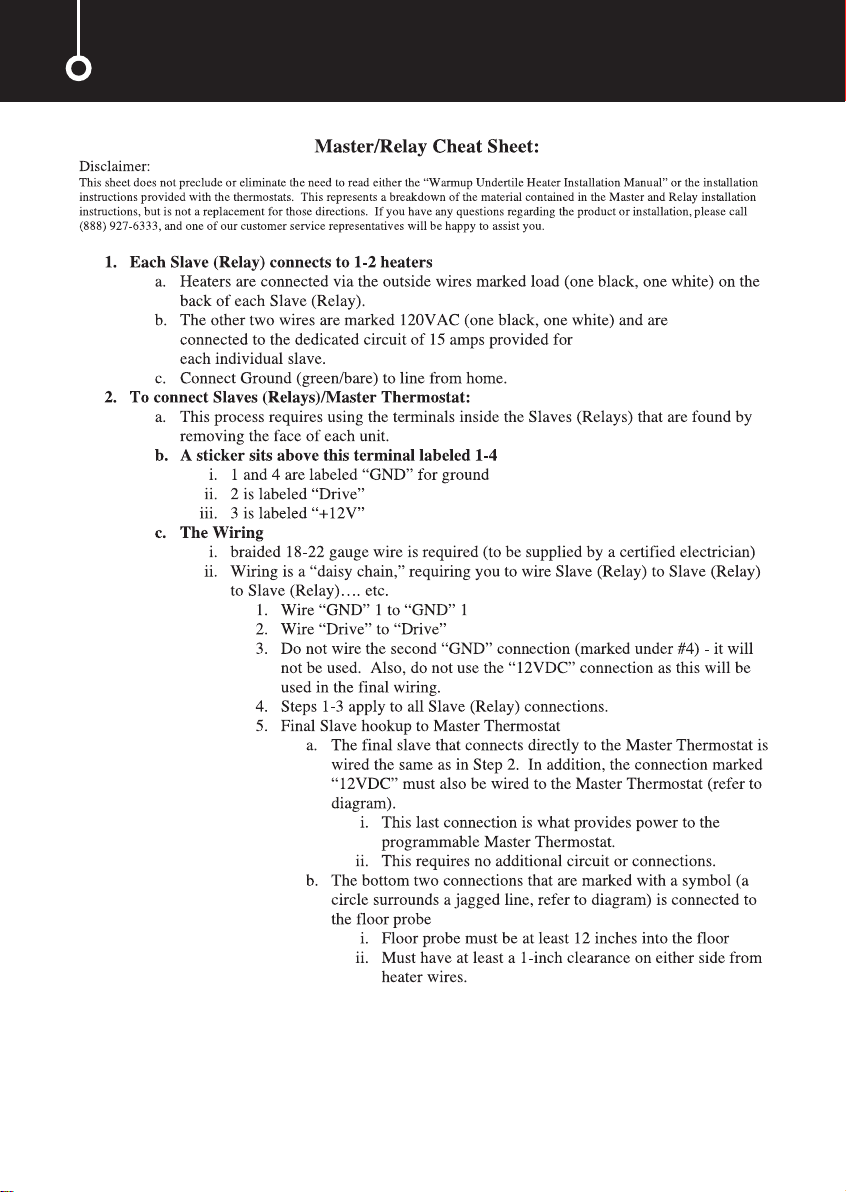
The Warmup thermostat has a maximum resistive load of 15 amps (i.e. a maximum of 2 x
USDW800). It also includes a built-in GFCI. If you want to control more than 15 amps worth of
heating via a single thermostat you will need to use Warmup’s master / relay configuration.
Instead of using the thermostat, a different model of master thermostat is used to control
individual switching units (each capable of switching up to a 15 amp load, and each containing
its own GFCI). The relay units requiretheir own separate electrical feed, and up to 10 relay
units can be daisy chained to a single master unit via low voltage cabling. For further
information please call the Warmup Helpline or visit www.warmup.com.
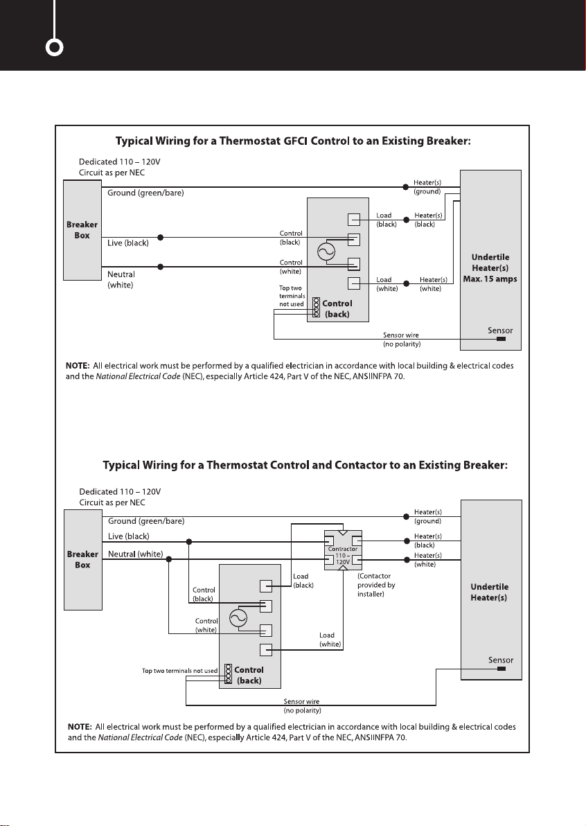
The thermostat should be connected to the main electrical supply via a fuse or circuit in
accordance with the National Electrical Code. If the thermostat used does not include a built-in
Ground Fault Circuit Interrupter (GFCI), then one must be added to the circuit between the
main power supply and the thermostat. If the thermostat does include a GFCI, it is NOT
recommended to include another in the circuit, as this may cause accidental tripping of the
control unit.
Ensuring Safety
Install the Warmup thermostat within thesameroom as the heater. In order to ensure the
efficient running of the system within bathrooms, we recommend that the controls are located
at least 36 inches away from shower openings or basin back splash areas so you minimize the
possibility of exposureto water.
The rating label in this manual must be attached to the circuit breaker box for referral by the
homeowner or electrical inspector. An additional smaller label is attached to the manual to be
fixed adjacent to or on the thermostatic control.

8
Do make sure all electrical work is done by qualified persons in accordance with local
building and electrical codes, the National Electrical Code (NEC), especially article 424,
Part V of the NEC, ANSI/NFPA 70.

9
Making electrical provision for the heater

10
Heater Information

11

To fully utilize the long-term durability of ceramic tiling, whether heated or not, it is important
that the design, construction and preparation of the subfloor is carried out correctly.
It is essential that the sub-floor be sufficiently rigid to support the ultimate weight that
it will have to bear without movement or deflection.
The choice of products for subfloor preparation and tile will vary depending on the existing
subfloor, preferred tiling system and choice of tile. This document is only intended to be an
outline guide to laying ceramic floor tiles. Further help regarding floor preparation and tile
application is available from the tile adhesive manufacturers and/or the Tile Council of
America (TCA) Tel: 864-646-8453, website: www.tileusa.com. Alternatively, you may wish to seek
professional advice e.g. an architect/contractor.
Subfloor Preparation
Prior to heater installation, it is important that the subfloor is properly prepared as per
Tile Council of America Guidelines.
WOOD SUBFLOOR: Boards need to be of suitable material or requires backer board. Chipboard
and O.S.B. boards (flake boards) are not suitable bases for ceramic floor tiling.
SUBFLOOR PREVIOUSLYCOVERED IN LINOLEUM, CORK OR CARPETING:All old flooringandadhesive
must be removed. If bitumen is present as adhesive residues it must be removed. If the bitumen
is a damp proofing membrane or isolation membrane it must be covered with a minimum 2” of
sand/cementself leveler,taking care not to puncture the bitumen coating. If using other damp
proofing or tanking systems, contact the manufacturer for advice.
We strongly recommend installing tile and stone flooring according to manufacturer’s recommendations, TCA guidelines
and ANSI specifications.
Special Precautions
MOSAIC TILE AND PORCELAIN: When installing mosaic tile and CERTAIN PORCELAIN, we
recommend a two-step process. Cover the space heating cable with latex self-leveling compound
before tiling to ensure a flat, smooth surface, then thin set the mosaic according to typical
practice.
EXPANSION JOINTS:Do not install the space heating cable through an expansion joint. Install
the space heating cable right up to the joint, if necessary, but do not bridge the joint.
INSULATION: Do not install rigid insulation directly above or below backer board or mortar.
If possible, install insulation as shown in diagrams.
Insulation dramatically enhances the performance and efficiency of floor warming systems.
Subfloor preparation - technical notes
12

Making Electrical Provision for the HeaterPreparation of wood or concrete subfloor
It is important to ensure that the thin set
(latex modified portland-based mortar),
latexmodified grout and backer board
have been fitted as per the manufacturers'
instructions.
Tiles Flexible tile adhesive
Heating wire Primer
3/4” plywood or Warmup
Insulation Board
2
3
4
5
1 2
3 4
5
Tiles Flexible tile adhesive
Heating wire Warmup Insulation board
Insulation board adhesive
Subfloor (concrete or timber)
1
2
3
4
5
6
21
34
5
6
1
13

Wiring configurations
14

Installing multiple undertile heaters
When installing two or more heaters, begin by reading the sizing guide on page 18 of this
booklet to ensure you have the proper number and size of heaters for the area you wish to
heat. The sizing guide will also tell you the perimeter and space heating cable spacing
required for your particular room size.
After you prime the subfloor, mark the subfloor as per the instructions on page 17 and lay the
first heater. Do not cover the first heater with tape at this point as you may wish to slightly alter
the spacings later on. Lay the second heater in the remaining area using the same perimeter and
space heating cable spacings as the first heater and test the second heater.
When laying morethan one heater,it is importantto keep these points in mind:
1The space heating cables may not touch or cross at any point.
2The heaters are joined in parallel only at the Thermostat.
Do not attach one heater to another in series.
3Thespace heating cable spacings for all heaters in an area should be approximately equal.
15

Paint the subfloor with Warmup® primer*.
Before applying the primer ensure that the floor surface
is smooth, dry and free from dust or grease.
If necessary, an appropriate smoothing compound
should be applied and allowed to cure.
If theheater is being fitted to a solid floor it is essential
that the concrete slab has been allowed to cure before
the primer is applied. This can take 8 weeks or more.
If tiling on existing ceramic or quarry floor tiles, clean
the floor with an appropriate floor-cleaning compound.
Do not apply the green Warmup® primer; go to installation
step 2.
If tilingon water proof/resistant surface (ie Hardibacker)
do not apply thegreen Warmup® primer; go to installation
step 2.
Using the roller supplied, apply the primer evenly to the
entire surface to be heated.
The primer must be allowed to dry for a minimum of 3 hours.
Thelightgreen color oftheprimer will change to a darker
green once dry and will be slightly sticky. Good ventilation
must be provided which, along with a higher ambient air
temperature, will accelerate the drying process.
Avoid traffic over the subfloor once the primer has
been applied.
Installation step 1
A
Smooth, clean and dry floor
B
Apply primer evenly
C
Avoid traffic over the primed floor.
IMPORTANT! – Test the Heater
Strip the ends of the cold lead wire and test the black &
white cables to ensure the heater is working properly.
Using a digital ohmmeter or multi-meter, check the
resistance of the space heating cable and continuity of the
protective groundbraid.Please note that analog meters
with a moving needle are not sufficiently accurate for
testing the Warmup heater.
Set your Ohm meter to measure resistance in 0 – 200 Ohms.
Acceptable readings of these ohms resistance measurements
(between theblack & white wires) should fall within +/-
15% of the values indicated on page 6.
Thereshould NOT be any continuity between the ground
wire and either of the white neutral wire or the black live
wire. Any continuity indicates there is a short in the circuit.
Test bT st a
D
*If the heater is being fitted to a wooden floor, the floor should be boarded over with tile
backer board or 3/4” plywood or Warmup® Insulation Board.
16
Test your heater

Making Electrical Provision for the HeaterInstallation step 2
Mark the heater position on the floor.
Calculate in square feet the size of the area to be heated.
Then, using the sizing guide on the opposite page, refer to
the space heating cable spacing and perimeter distances to
correctly fit your space heating cable into the space
available.
Using a fiber tipped pen, mark a start point as close as
possible to the power supply, but no further than 8 feet
from it using the sizing guide on the opposite page.
Mark all the outer corners of the heated area observing the
perimeter distances referred to in the sizing guide and join
the corners up to form a marked out perimeter.
Mark up the spacing intervals for the space heating cable
following the sizing guide.
The spacing between heater cables must be a
minimum of 2" apart, but not further than 4"
apart. Atno time,should the space heating
cables be less than 2" from the wall.
Note: The entire heater must be kept on the
same level; do not lay the heaters on stairways
or up walls.
A
Measure up
B
Mark start point
C
Mark perimeter and spacing intervals
17

Sizing guide
If your area is above 119ft2please contact the Warmup Technical Helpline
on 888-927-6333 for assistance.
NOTE: All spacing has been based on square areas for calculation purposes.
Therefore, actual spacing will vary according to the shape of the area
to be heated.
Area (sq ft) Heater(s) Spacing in (s) Perimeter in (p)
15-16 USDW360 2 1/4 2
17-18 USDW360 2 3/4 2
19-20 USDW360 3 1/4 2
21-24 USDW360 4 2
25-26 USDW480 2 3/4 2
27-28 USDW480 3 1/4 2
29 USDW480 3 1/4 2
30-32 USDW480 2 2/4 2
33-34 USDW480 4 2
35 USDW720 2 1/4 2
36-41 USDW720 2 3/4 2
42-44 USDW720 3 1/4 2
45-49 USDW950 21/4 2
50-56 USDW950 2 3/4 2
57-59 USDW950 3 1/4 2
60-68 USDW480+USDW720 2 3/4 2
69-72 USDW480+USDW720 3 1/4 2
73-74 USDW480+USDW720 3 2/4 2
75-78 USDW950+USDW480 2 3/4 2
79-87 USDW950+USDW480 3 1/4 2
88-89 USDW950+USDW480 3 2/4 2
90-92 USDW720+USDW950 2 3/4 2
93-98 USDW720+USDW950 3 2
99-104 USDW720+USDW950 3 1/4 2
105-106 2xUSDW950 2 3/4 2
107-112 2xUSDW950 3 2
113-119 2xUSDW950 3 1/4 2
120 volt sizing guide
18

Installation step 3
Once the floor has been marked up, the space
heating cable can be laid out. Test heater
throughout installation.
Gently pull the unheated lead from the box.
Do not remove the spool from the box as this will cause the
space heating cable to twist.
After 9 feet of cable has been removed, you will reach the
point at which the unheated lead joins the space heating
cable.
The joint should be taped to the floor at the start point.
Ensure that the factory joint lays flat on the floor. Care
should be taken to ensure that the factory joint remains
horizontal, and within the area to be tiled. The joint should
not be bent at point of entry into the conduit as this may
damage both the factory joint and /or the heating element
within.
Thespace heatingcable should be laidin parallel lines back
andforth across the main body of the area to be heated.
Using the cable spacing markings as tape down points,
securethespace heatingcable to thefloor with strips of
adhesive tape supplied.
The strips should be about 1 inch long.
A
Lay space heating cable out from
start point
B
Lay out space heating cable in
parallel lines
C
Space and secure with fixing tape
D
Tape down end point.
19

Making Electrical Provision for the Heater
You may wish to alter the space heating cable layout to fit
your particular room.
Where there are irregularities of room shape you can adjust
the layout of the space heating cable to provide warmth
around the sinks, tubs, toilets, etc. (see layout diagram page 14).
This is quite acceptable providing that:
•The space heating cables are spaced at least 2” apart at
all times.
•The space heating cables never cross.
IMPORTANT! – Test the Heater
Once the space heating cable layout has been completed,
ensure that the heater is working properly.
Using a digital ohmmeter or multi-meter, check the resistance
ofthespace heating cable and continuity of the protective
ground braid. Please note that analog meters with a moving
needle are not sufficiently accurate for testing the Warmup
heater.
Set your Ohm meter to measure resistance in 0 – 200 Ohms.
Acceptable readings ofthese ohms resistance measurements
(between the black & white wires) should fall within +/- 15%
of the values indicated on page 6.
There should NOT be any continuity between the ground wire
andeither ofthewhite neutral wire or the black live wire.
Anycontinuity indicates there is a short in the circuit.
Theentire length of the space heating cable should then be
taped to thefloor.
Ensure the greatest possible adhesion, with the minimum of
trapped air space beneath the taped space heating cable.
After applying a length of tape, run your forefinger and thumb
alongthelength of the space heating cable, gently squeezing
thespace heatingcable to remove anyair space between the
space heating cable and the tape. As you apply the tape,
gently tighten the space heating cable from the ends to
ensure it is straight.
The space heating cable should be located in the center of the
tape to provide maximum protection from the tiler’s trowel. If
the tape is not completely covering the space heating cable at
any point, apply another layer of tape to provide additional
protection.
E
Lay out balance of space heating
cable
F
Adjust space heating cable
spacings if necessary
H
Position Tape centrally and tape
down entire space heating cable
Test bT
G
Test your heater
20
This manual suits for next models
3
Table of contents
Other Warmup Heater manuals