Water Depot Deluxe Series User manual

By Water Depot
DELUXE SERIES
OWNER’S MANUAL
FOR ALL DELUXE WATER SOFTENERS
THIS MANUAL IS TO BE LEFT WITH THE OWNER OF THE EQUIPMENT FOR REFERENCE AND
PURPOSES AND TECHNICAL GUIDANCE. IT IS STRONGLY RECOMMENDED THAT QUALIFIED
DEALER SERVICE PERSONNEL BE CONTACTED IN THE EVENT OF AN UNKNOWN INTERRUPTION
OF SERVICE OR APPARENT PRODUCT MALFUNCTION. AN ANNUAL PREVENTATIVE MAINTENANCE
INSPECTION BY A WATER PROFESSIONAL IS RECOMMENDED TO ENSURE TROUBLE-FREE AND
CONTINUOUS OPERATION.
www.waterdepotinc.com

1
TABLE OF CONTENTS
Control Valve Specifications 2
Control Valve Function and Cycles of Operation 3
General Instructions 7
System Setup 8
Setting Options Table 11
Bypass Valve 12
Installation 13
Installer Settings 15
Normal Display Settings 16
General Information 18
Start Up Instructions 19
Drawings and Part Numbers
MR Front Cover and Drive Assembly 20
WS1MR Drive Cap, Pistons and Spacer Stack 21
Replacement Parts 22
Installation Fittings Assemblies 26
WS1 Identification Figure 27
Troubleshooting 28
FOR INFORMATION COMMON TO ALL 1” CONTROL VALVES REFER TO THE WS1 DRAWINGS AND
SERVICE MANUAL
PRE-INSTALLATION INSTRUCTIONS
This unit has a control valve which enables the setting of not only the length of each regeneration cycle but also the
order in which cycles (steps of regeneration) occur. The following pages instruct how to choose the unit‟s sequence
of cycles, cycle times, exchange capacity, and gallon capacity/regeneration time.
THE DEALER…
1. Read this page, GENERAL INSTRUCTIONS, INSTALLER SETTINGS, NORMAL DISPLAY SETTINGS.
2. Read the CYCLE VALVE FUNCTION AND CYCLES OF OPERATION.
3. Complete the SYSTEM SETUP.
THE INSTALLER…
1. Read Bypass Valve page.
2. Read GENERAL INSTRUCTIONS, NORMAL DISPLAY SETTINGS.
3. Be sure CYCLE VALVE FUNCTION AND CYCLES OF OPERATION and SYSTEM SETUP are done
before leaving for installation.
4. Follow INSTALLATION instructions, INSTALLER SETTINGS, TIME OF DAY.
5. Follow START UP INSTRUCTIONS.
2
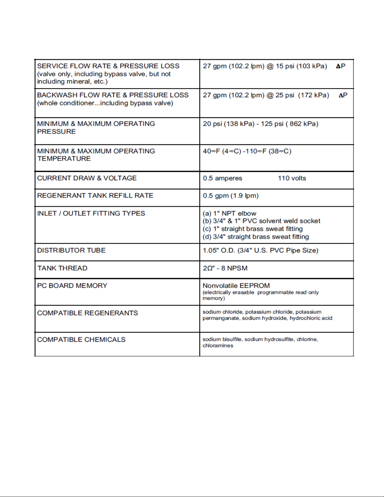
CONTROL VALVE SPECIFICATIONS

3
CONTROL VALVE FUNCTION AND CYCLES OF OPERATION
This glass filled Noryl¹ (or equivalent) fully automatic control valve is designed as the primary control center to direct
and regulate all cycles of a water softener or filter. When the WS1MR control valve is manufactured as a softener,
the control valve can be ordered to perform downflow or upflow regeneration. The WS1.25MR control valve is only
available in downflow regeneration. When the WS1MR or WS1.25MR control valve is set up as a filter, the control
valve can be set to perform downflow regeneration or simply backwash. The control valve can be set to regenerate
on demand (consumption of a predetermined amount of water) and/or as a time clock (passage of a particular
number of days). The control valve can be set so that a softener can meet the Water Quality Association (WQA)
Standard S100 or NSF/ANSI Standard 44 efficiency rating.
It is not recommended to change control valves from downflow to upflow brining or vice versa in the field.
The valve bodies for downflow and upflow are unique to the regeneration type and should not be
interchanged. A mismatch of valve body and regeneration piston will result in hard water bypass during
service.
The control valve is compatible with a variety of regenerants and resin cleaners. The control valve is capable of
routing the flow of water in the necessary paths to regenerate or backwash water treatment systems. The injector
regulates the flow of brine or other regenerants. The control valve regulates the flow rates for backwashing, rinsing,
and the replenishing of treated water into a regenerant tank, when applicable.
The control valve uses no traditional fasteners (e.g. screws); instead clips, threaded caps and nuts and snap type
latches are used. Caps and nuts only need to be firmly hand tightened because radial seals are used. Tools
required to service the valve include one small blade screw driver, one large blade screw driver, pliers and a pair of
hands. A plastic wrench is available which eliminates the need for screwdrivers and pliers. Disassembly for
servicing takes much less time than com parable products currently on the market. Control valve installation is
made easy because the distributor tube can be cut ½” above to ½” below the top of tank thread. The distributor tube
is held in place by an o-ring seal and the control valve also has a bayonet lock feature for upper distributor baskets.
The AC adapter power pack comes with a 15 foot power cord and is designed for use with the control valve. The
AC adapter power pack is for dry location use only. The control valve remembers all settings for two hours if the
power goes out. After two hours, the only item that needs to be reset is the time of day; all other values are
permanently stored in the non-volatile memory. The control valve does not need batteries.
The control valve‟s unique design and electronics allow the OEM to select:
1.a pre or post fill option with up or down flow and adjust the length of the cycles; or
2.a pre or post fill option, select a program code that has a preset cycle order/value and adjustable fill cycle.
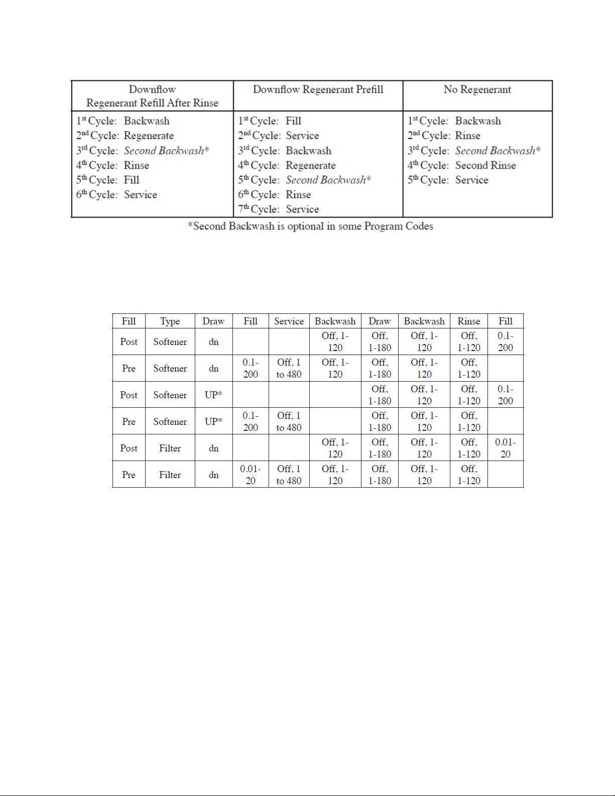
Tables 1 and 2 show examples when the valve is set up as a softener or a filter.
WS1MR
Downflow Regenerant
Refill After Rinse
1st Cycle Backwash
2nd Cycle Regenerate
3rd Cycle Second
Backwash*
4th Cycle Rinse
5th Cycle Fill/Dissolve
6th Cycle Service
WS1MR
Downflow Regenerant
Prefill
1st Cycle Fill
2nd Cycle Service
3rd Cycle Backwash
4th Cycle Regenerate
5th Cycle Second
Backwash*
6th Cycle Rinse
7th Cycle Service
WS1MR
Upflow Regenerant
Refill After Rinse
1st Cycle Regenerate
2nd Cycle Backwash
3rd Cycle Rinse
4th Cycle Fill/Dissolve
5th Cycle Service
WS1MR
Upflow Regenerant
Prefill
1st Cycle Fill
2nd Cycle Service
3rd Cycle Regenerate
4th Cycle Backwash
5th Cycle Rinse
6th Cycle Service
* Second Backwash is optional
1Noryl is a trademark of General Electric.
4
ADJUSTABLE CYCLES
Table 3 shows the order and cycle times for the adjustable cycles.
PRESET PROGRAM CODES
A variety of preset program codes are available. Softener program codes refill in pounds of salt and filter program
codes refill in gallons. Tables 4, 5, 6 and 7 show the length of the cycles when different program codes are
selected. The OEM has the option of having the regenerant refill after the rinse cycle or have the regenerant prefill
before regeneration. If the OEM chooses to have the regenerant prefill before regeneration, the prefill starts four
hours before the regeneration time set. During the 4-hour period in which the brine is being made, treated water is
still available. For example: regeneration time = 2:00 am, prefill option selected, downflow softener. Fill occurs at
10:00 p.m., start of backwash cycle occurs at 2:00 a.m.
Table 2
Regeneration Cycles Filtering
Table 3
Fill values are pounds of salt if softening is selected and gallons if filtering is selected. All other values are in minutes.

5
Table 4
Down Flow Softener Program Codes
Table 5
Up Flow Softener Program Codes
Table 6
Regenerating Filter Program Codes
Table 7
Non-Regenerating Filter Program Codes

6
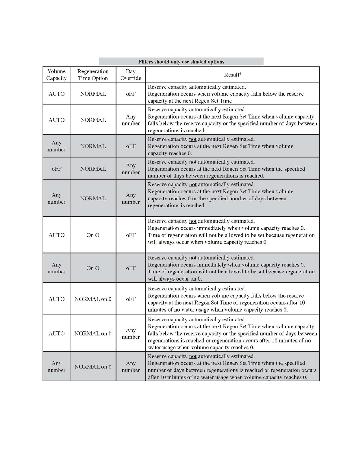
The control valve with a water meter can be set for Demand Initiated Regeneration (DIR) only, Time Clock
operation only or DIR and Time Clock whichever comes first, depending upon what settings are selected for Day
Override and Gallon Capacity.2 See Table 8.
If a control valve does not contain a meter, the valve can only act as a time clock, and day override should be set to
any number and gallon capacity should be set to off.
For DIR Softeners, there are two options for setting the Gallons Capacity. The Gallons Capacity is automatically
calculated if set to AUTO. Reserve Capacity is automatically estimated based on water usage if AUTO is used. The
other option is to set the Gallons Capacity to a specific number. If a specific number is set, reserve capacity is zero,
unless the value is manually set (i.e. the manufacturer intentionally sets the gallon capacity number below the
calculated capacity of the system).
The control valve can also be set to regenerate immediately or at the next regeneration time by changing the
Regeneration Time Option. There are three choices for settings:
1. “NORMAL” means regeneration will occur at the preset regeneration time.
2. “on 0” means regeneration will occur when the gallons capacity reaches zero.
3. “NORMAL” and “on 0” means the regeneration will occur at the preset regeneration time unless the gallons
capacity reaches zero. If the gallons capacity reaches zero the regeneration will begin 10 minutes after no water
usage.
The user can initiate manual regeneration. The user has the option to request the manual regeneration at the
delayed regeneration time or to have the regeneration occur immediately:
1. Pressing and releasing the REGEN button. “Regen Today” will flash on the display and the regeneration will
occur at the delayed regeneration time. The user can cancel the request by pressing and releasing the REGEN
button. This method of manually initiating regeneration is not allowed when the system is set to “on 0,” i.e.
immediately regenerate when the gallon capacity reaches zero.
2. Pressing and holding the REGEN button for approximately 3 seconds will immediately start the regeneration. The
user cannot cancel this request, except by resetting the control by pressing NEXT and REGEN buttons
simultaneously for 3 seconds.
A unique feature of this control valve is the ability to display actual water usage for the last 63 days. The values are
initially stored as “----”. This means the value is unknown. As days pass values are stored as “0” for no flow or the
actual number of gallons. The counting of the gallons starts at the regeneration time. If no regeneration time can be
set (i.e. when the valve is set for immediate regeneration) the counting of gallons starts at 12 a.m. Day 1 is
yesterday, day 2 the day before yesterday, etc. As new values are added the oldest history disappears.
Another unique feature is that the valve automatically calculates a reserve capacity when set up as a softener with
“Gallons Capacity” set to “AUTO” and the “Regeneration Time Option” set to “Normal” or “Normal + on 0”. The
actual reserve capacity is compared to the gallons capacity remaining immediately prior to the preset regeneration
time. A regeneration will occur if the actual reserve capacity is less than the gallons capacity remaining. The actual
reserve capacity is calculated by using the estimated reserve capacity and adjusting it up or down for actual usage.
The estimated reserve capacity for a given day of the week is the maximum value stored for the last three non-trivial
water usages (i.e. more than 20 gallons/day) in seven day intervals.
² See Installer Display Settings Step 3I, OEM System Setup Step 7S for explanations of Day Override and Gallon
Capacity.
³ Day Override and Gallon Capacity cannot both be set to “oFF” at the same time.

7
GENERAL INSTRUCTIONS
The control valve offers multiple procedures that allow the valve to be modified to suit the needs of the installation.
These procedures are:
System Setup
Installer Settings
Normal Display Settings
Diagnostics
Valve History
These procedures can be accessed in any order. Details on each of the procedures are provided on the following
pages.
At the discretion of the manufacturer, the field technician can access all settings. To “lock out” access to diagnostic
and valve history displays and modifications to settings except hardness, day override, time of regeneration and
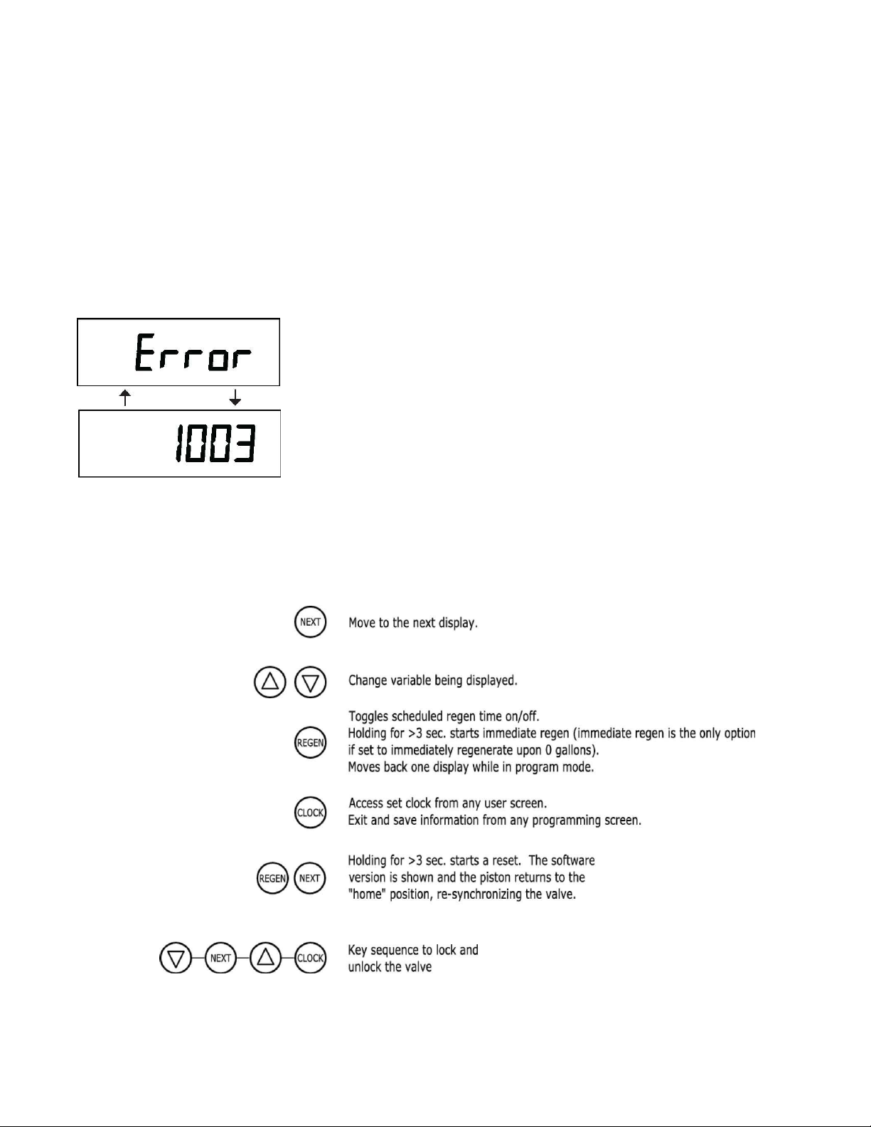
time of day by anyone but the manufacturer, press ▼, NEXT, ▲, CLOCK in sequence after settings are made. To
“unlock”, so other displays can be viewed and changes can be made, press ▼, NEXT, ▲, and CLOCK in sequence.
When in operation normal user displays such as time of day, gallons remaining or days remaining before
regeneration, current flow rate or total gallons used are shown. When stepping through a procedure, if no buttons
are pressed within five minutes the display returns to a normal user display. Any changes made prior to the five
minute time out are incorporated.
To quickly exit Installer Display Settings, Diagnostics or Valve History press CLOCK. Any changes made prior to the
exit are incorporated.
Sometimes it is desirable to have the valve initiate and complete two regenerations within 24 hours and then return
to the preset regeneration procedure. It is possible to do a double regeneration if the control valve is set to
“NORMAL” or “NORMAL + on 0” in OEM System Setup. To do a double regeneration:
Press the “REGEN” button once. REGEN TODAY will flash on the display.
Press and hold the “REGEN” button for three seconds until the valve regeneration initiates.
Once the valve has completed the immediate regeneration, the valve will regenerate one more time at the preset
regeneration time.
8
SYSTEM SETUP
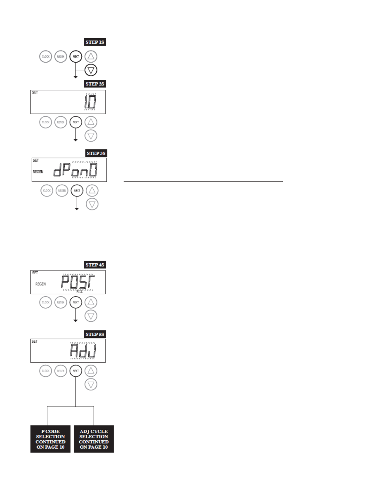
STEP 1S –Press NEXT and ▼ buttons simultaneously for 3 seconds. If screen in
step 2S does not appear in 5 seconds the lock on the valve is activated. To unlock
press ▼, NEXT, ▲, and CLOCK in sequence, then press NEXT and ▼
simultaneously for 3 seconds.
STEP 2S –Use the ▲ or ▼ buttons to select 1.0 for WS1MR or 1.25 for the
WS1.25MR. Press NEXT to go to step 3S.
STEP 3S
STEP 3S –Allows selection of one of the following using the ▲ or ▼ buttons:
•an outside signal to initiate a regeneration;
•an outside signal to prevent or delay a regeneration.
Selecting the use of an outside signal to initiate a regeneration:
Selection only matters if a connection is made to the two pin connector labeled DP
SWITCH located on the printed circuit board. Following is an explanation of the
options:
Off - Feature not used. dPon0 - If the dP switch is closed for an accumulative time of 2
minutes a regeneration will occur immediately.
dPdEL - If the dP switch is closed for an accumulative time of 2 minutes a
regeneration will occur at the scheduled regeneration time.
HoLd - If the dP switch is closed a regeneration will be prevented from occurring.
Press NEXT to go to Step 4S.
STEP 4S
STEP 4S –Set Refill option using ▲ or ▼ buttons:
•“PoST” to refill the brine tank after the final rinse; or
•“PrE” to refill the brine tank four hours before the regeneration time set.
Press NEXT to go to Step 5S.
STEP 5S
STEP 5S –Set method for regeneration cycles by using the ▲ or ▼ buttons:
•“Adj” allows manual setting of regeneration cycle times; or
•Choose a P Code with fixed regeneration cycle sequences and times.
Press NEXT.
P CODE ADJ CYCLE
ON PAGE 10 ON PAGE 10
8S
9
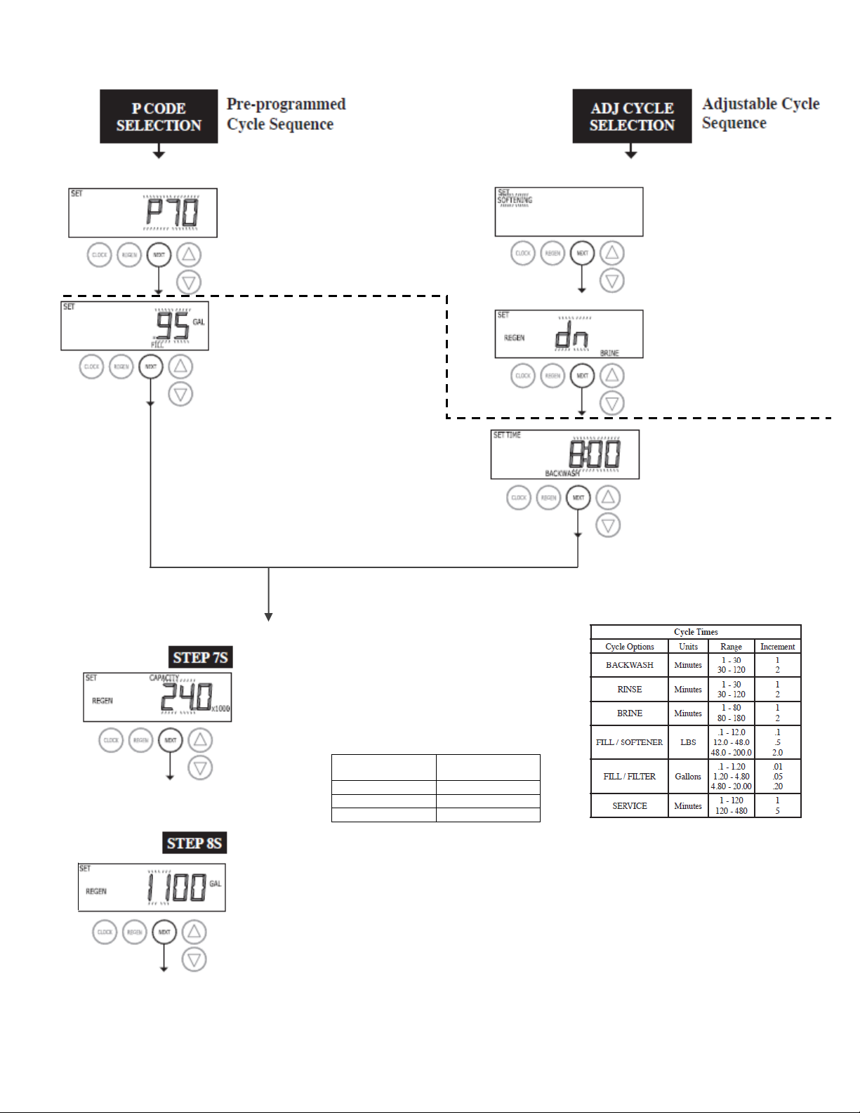
P-Code 1
Selecting pre-set programs. If the unit
is set to 1.25, P60 - P69 will not be
available.
P-Code 2
Set pounds of salt or gallons of
fill. Ranges and increments should
be as shown in Cycle Times table,
but can not be set to OFF.
P1 - P69 = lb (unit measure)
P70 - P79 = Gal (unit measure)
P80 - P99 = No Screen
Press NEXT to go to Step 7S
STEP 7S
System ionic capacity. Enter the ion exchange capacity
in grains of hardness as calcium carbonate for the system
based on test data using ▲or▼buttons. This screen is
not available except when configured P1 - P69 or an Adj
softener.
Press NEXT to go to Step 8S. Press REGEN to return
to the previous step.
STEP 8S - Set Gallons Capacity using ▲or▼buttons:
•“AUTO” (reserve capacity automatically estimated and gallons capacity automatically
calculated from grains capacity and water hardness);
•“oFF” (regeneration based on day override); or
•number of gallons (20 to 250,000).
Note: OFF will not be an option if days override is not set. Auto is not an option on a filter or P70 -
P88. See Setting Options Table for more details.
Press NEXT to go to Step 9S. Press REGEN to return to previous step.
Range (Grains)
Increment
5.0 - 50.0 x1000
500
50.0 - 200.0 x1000
2,000
200.0 - 500.0 x1000
5,000
Adj1
Select between
SOFTENING or FILTTHE
Adj2
Set upflow or downflow
regeneration on a 1” control.
This screen will not display if
the unit is set up as a1.25”
or filter valve.
Adj3
Set cycle times. OFF will be
an option in all cycles.
Press NEXT to go to Step
7S
Select between
SOFTENING or FILTTHE
10
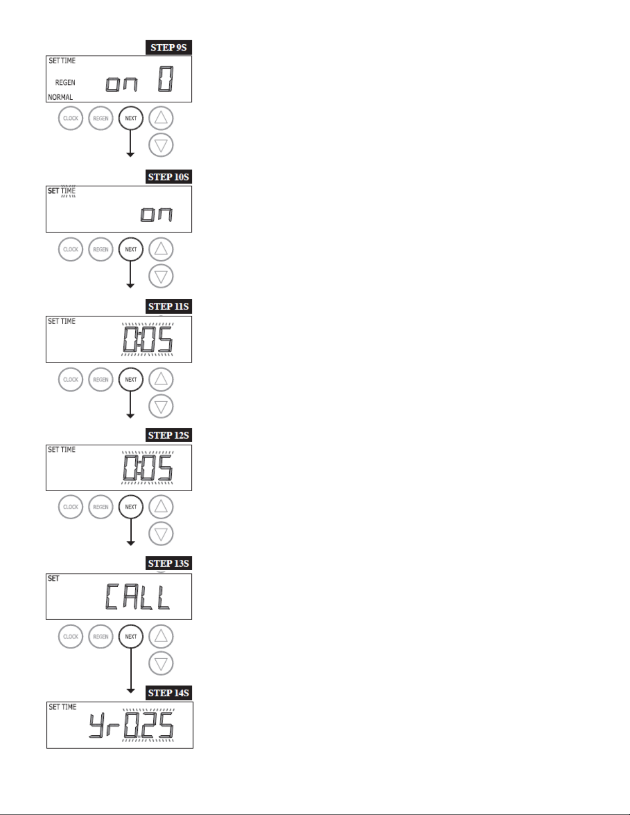
TEP 10Step 9S –Set Regeneration Time Options using the ▲ or ▼ buttons:
•“NORMAL” means regeneration will occur at the preset time;
•“on 0” means regeneration will occur immediately when the gallons capacity
reaches 0 (zero); or
•“NORMAL + on 0” means regeneration will occur at one of the following:
•the preset time when the gallons capacity falls below the reserve or the specified
number of days between regenerations is reached, whichever comes first; or
•after 10 minutes of no water usage when the gallon capacity reaches 0 (zero).
See Setting Options Table for more detail. Press NEXT to go to Step 10S. Press REGEN
to return to previous step.
Step 10S: Set Relay operation using the ▲ or ▼ button. The choices are:
•Set Time on: Relay activates after a set time at the beginning of a regeneration and
then deactivates after a set period of time. The start of regeneration is defined as
the first backwash cycle, Dn brine cycle or UP brine cycle which ever comes first.
•Set Gal on: Relay activates after a set number of gallons and then deactivates after
a set period of time or after the meter stops registering flow, whichever comes first.
•Set Off: If set to Off, Steps 11S and 12S will not be shown.
Press NEXT to go to Step 11S. Press REGEN to return to previous step.
Step 11S: Set Relay Actuation Time or Gallons using the ▲ or ▼ buttons. The choices
are:
•Relay Actuation Time: After the start of a regeneration the amount of time that
should pass prior to activating the relay. The start of regeneration is defined as the
first backwash cycle, Dn brine cycle or UP brine cycle which ever comes first.
•Relay Actuation Gallons: Relay activates after a set number of gallons has passed
through the meter.
Ranges from 1 to 50 gallons.
Press NEXT to go to Step 12S. Press REGEN to return to previous step.
Step 12S: Set Relay Deactivate Time using the ▲ or ▼ buttons.
•If Set Time on is selected in Step 10S the relay will deactivate after the time set has
expired. Ranges from 1 second to 200 minutes.
•If Set Gal on is selected in Step 10S the relay will deactivate after the time set has
expired or after the meter stops registering flow, whichever comes first. Ranges
from 1 second to 20 minutes.
Press NEXT to go to Step 13S. Press REGEN to return to previous step.
Step 13S: Set the Service Call Indicator using the ▲ or ▼ buttons. The choices are Time,
GAL or oFF.
•Time means a call indicator will be displayed after the preset time has expired. The
range is from .25 to 9.75 years.
•GAL means a call indicator will be displayed after the present number of gallons
has been used. The range is from 100 to 9,999,000 gallons.
Press NEXT to go to Step 14S. Press REGEN to return to previous step.
Step 14S: Use the ▲ or ▼ buttons to adjust Time or Gallons. Press NEXT to exit System
Setup.
Press REGEN to return to previous step.
11
SETTING OPTIONS TABLE
STEP 1I
STEP 2I
STEP 3I
STEP 4I
4Reserve capacity estimate is based on history of water usage
12
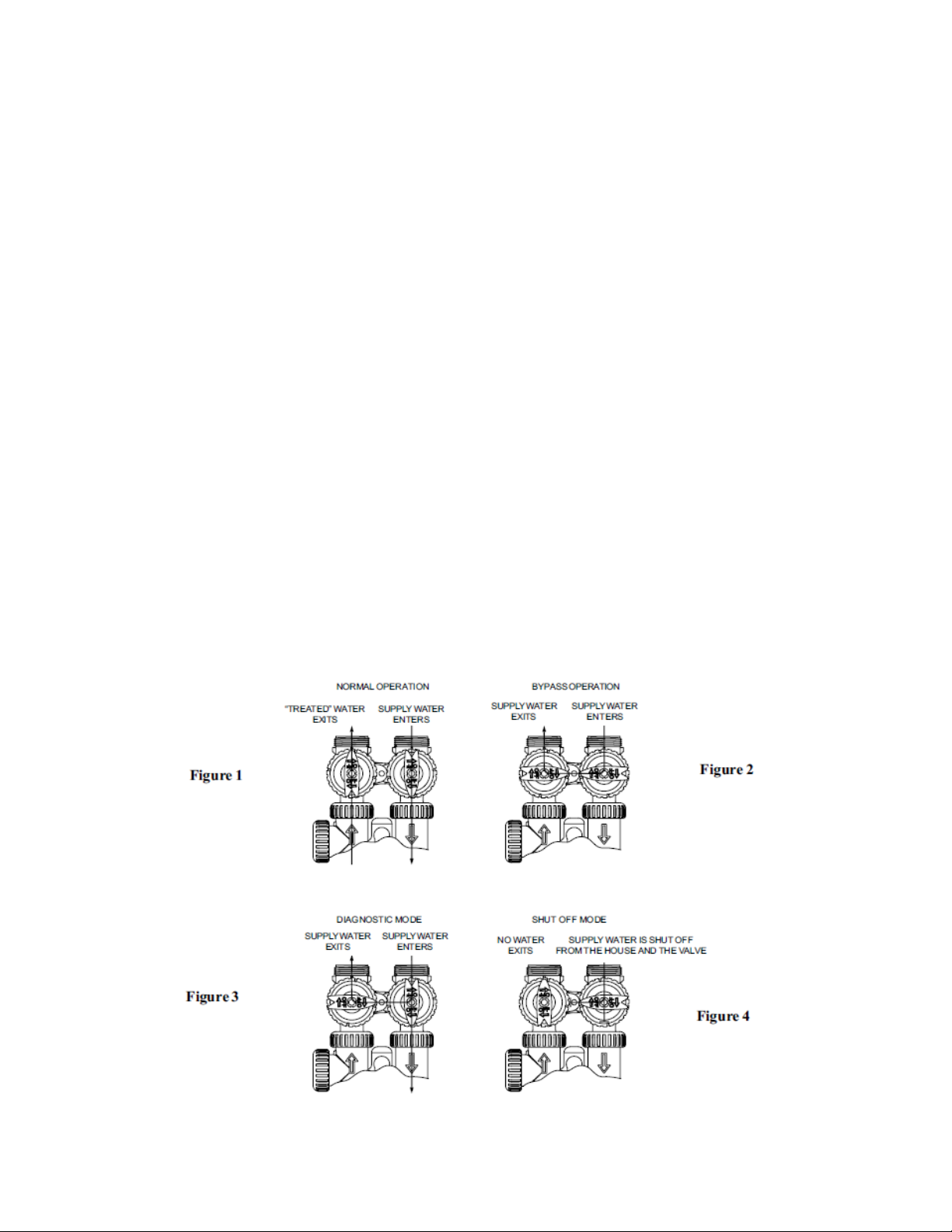
BYPASS VALVE
The bypass valve is typically used to isolate the control valve from the plumbing system‟s water pressure in order to
perform control valve repairs or maintenance. The 1" full flow bypass valve incorporates four positions including a
diagnostic position that allows a service technician to have pressure to test a system while providing untreated
bypass water to the building.
The bypass body and rotors are glass filled Noryl and the nuts and caps are glass filled polypropylene. All seals are
self-lubricating EPDM to help prevent valve seizing after long periods of non-use. Internal o-rings can easily be
replaced if service is required.
The bypass consists of two interchangeable plug valves that are operated independently by red arrow shaped
handles. The handles identify the direction of flow. The plug valves enable the bypass valve to operate in four
positions.
1. Normal Operation Position: The inlet and outlet handles point in the direction of flow indicated by the engraved
arrows on the control valve. Water flows through the control valve for normal operation of a water softener or filter.
During the regeneration cycle this position provides regeneration water to the unit, while also providing untreated
water to the distribution system. (See Figure 1)
2. Bypass Position: The inlet and outlet handles point to the center of the bypass.
The system is isolated from the water pressure in the plumbing system.
Untreated water is supplied to the building. (See Figure 2)
3. Diagnostic Position: The inlet handle points toward the control valve and the outlet handle points to the center
of bypass valve.
Untreated supply water is allowed to flow to the system and to the building, while not allowing water to exit from the
system to the building (See Figure 3).
This allows the service technician to draw brine and perform other tests without the test water going to the building.
NOTE: The system must be rinsed before returning the bypass valve to the normal position.
4. Shut Off Position: The inlet handle points to the center of the bypass valve and the outlet handle points away
from the control valve. The water is shut off to the building.
The water treatment system will depressurize upon opening a tap in the building. A negative pressure in the building
combined with the softener being in regeneration could cause a siphoning of brine into the building.
If water is available on the outlet side of the softener or filter it is an indication of water bypassing the system (i.e. a
plumbing cross-connection somewhere in the building). (See Figure 4)

13
INSTALLATION
GENERAL INSTALLATION & SERVICE WARNINGS
The control valve, fittings and/or bypass are designed to accommodate minor plumbing misalignments but are not
designed to support the weight of a system or the plumbing.
Do not use Vaseline, oils, other hydrocarbon lubricants or spray silicone anywhere. A silicone lubricant may be used
on black o-rings, but is not necessary. Avoid any type of lubricants, including silicone, on red or clear lip
seals.
Do not use pipe dope or other sealants on threads. Teflon tape must be used on the threads of the 1" NPT
elbow, its ˘" NPT connection, and on the threads for the drain line connection. Teflon tape is not used on the nut
connections or caps because o-ring seals are used. The nuts and caps are designed to be unscrewed or tightened
by hand or with the special plastic Service Wrench, #V3193. If necessary a pliers can be used to unscrew the nut or
cap. Do not use a pipe wrench to tighten nuts or caps.
Do not place screwdriver in slots on caps and/or tap with a hammer.
SITE REQUIREMENTS
Water Pressure, 20-125 psi (138-862 kPa). ●Current draw is 0.5 amperes.
Water temperature, 40° -110° F (4° - 38° C) ●A 15 ft power cord is furnished.
The tanks should be on a firm level surface ●The plug-in transformer is for dry locations only.
Electrical: Use a 115/120V, 60Hz uninterrupted outlet. ●Batteries are not used.
1. The distance between the drain and the water conditioner should be as short as possible.
2. Since salt must be periodically added to the brine tank, it should be located where it is easily accessible.
3. Do not install any water conditioner with less than 10 feet (3m) of piping between its outlet and the inlet of a water
heater. Water heaters sometimes overheat to the extent that they will transmit heat or backflow from their inlet back
to the water conditioner control. Hot water can severely damage the conditioner. Allowing the 10 foot (3m) distance
will permit most heat to dissipate before reaching the water conditioner. A more positive way of insuring against
backflow is to install a high temperature check valve. The heater should also have a properly rated temperature and
pressure relief valve. Also, be certain that local codes are not violated.
4. Do not locate unit where it or its connections (including the drain and overflow lines) will ever be subjected to
room temperatures under 34° F (49° C).
5. The use of resin cleaners in an unvented enclosure is not recommended.
SERIAL NUMBER: Record the serial number on the installer‟s and customer‟s records.

14
INSTALLATION
INLET/OUTLET PLUMBING: Connect to a supply line downstream of outdoor spigots. Install an inlet shutoff valve
and plumb to the unit‟s bypass valve inlet located at the right rear as you face the unit. There are a variety of
installation fittings available. They are listed under Installation Fitting Assemblies. When assembling the
installation fitting package (inlet and outlet), connect the fitting to the plumbing system first and then attach the nut,
split ring and o-ring. Heat from soldering or solvent cements may damage the nut, split ring or o-ring. Solder joints
should be cool and solvent cements should be set before installing the nut, split ring and o-ring. Avoid getting solder
flux, primer, and solvent cement on any part of the o-rings, split rings, bypass valve or control valve. If the building‟s
electrical system is grounded to the plumbing, install a copper grounding strap from the inlet to the outlet pipe.
Plumbing must be done in accordance with all applicable local codes.
DRAIN LINE: First, be sure that the drain can handle the backwash rate of the system. Solder joints near the drain
must be done prior to connecting the drain line flow control fitting. Leave at least 6" between the drain line flow
control fitting and solder joints. Failure to do this could cause interior damage to the flow control. Install a ˚" I.D.
flexible plastic tube to the Drain Line Assembly or discard the tubing nut and use the ¾ " NPT fitting for rigid pipe. If
the backwash rate is greater than 7 gpm, use a ¾ " drain line. Where the drain line is elevated but empties into a
drain below the level of the control valve, form a 7" (18 cm) loop at the discharge end of the line so that the bottom
of the loop is level with the drain connection on the control valve. This will provide an adequate anti-siphon trap.
Where the drain empties into an overhead sewer line, a sink-type trap must be used. Run drain tube to its discharge
point in accordance with plumbing code. Pay special attention to codes for air gaps and anti-siphon devices.
IMPORTANT:
Never insert a drain line directly into a drain, sewer line, or trap. Always allow an air gap
between the drain line and the wastewater to prevent the possibility of sewage being back-
siphoned into the conditioner.
BRINE TANK CONNECTION: Install a 3/8" O.D. polyethylene tube from the Refill Elbow to the Brine Valve in the
brine tank.
OVERFLOW LINE CONNECTION:
AN OVERFLOW DRAIN LINE IS RECOMMENDED WHERE A BRINE OVERFLOW COULD DAMAGE
FURNISHINGS OR THE BUILDING STRUCTURE.
Your softener is equipped with a brine tank safety float which greatly reduces the chance of an accidental brine
overflow. In the event of a malfunction, however, an OVERFLOW LINE CONNECTION will direct the “overflow” to
the drain instead of spilling on the floor where it could cause considerable damage. This fitting should be on the side
of the cabinet or the brine tank.
To connect overflow fitting, locate hole in side of brine tank. Insert overflow fitting into tank and tighten with plastic
thumb nut and gasket from the inside. Attach a length of ˚" (1.3 cm) I.D. tubing (not supplied) to fitting and run to
drain. Do not elevate overflow line higher than 3" (7.6 cm) below bottom of overflow fitting. Do not “tie” this tube into
the drain line of the control valve. Overflow line must be a direct, separate line from overflow fitting to drain, sewer,
or tub. Allow an air gap as per the drain line instructions.
IMPORTANT:
Never insert a drain line directly into a drain, sewer line, or trap. Always allow an air gap
between the drain line and the wastewater to prevent the possibility of sewage being
back-siphoned into the conditioner.
15
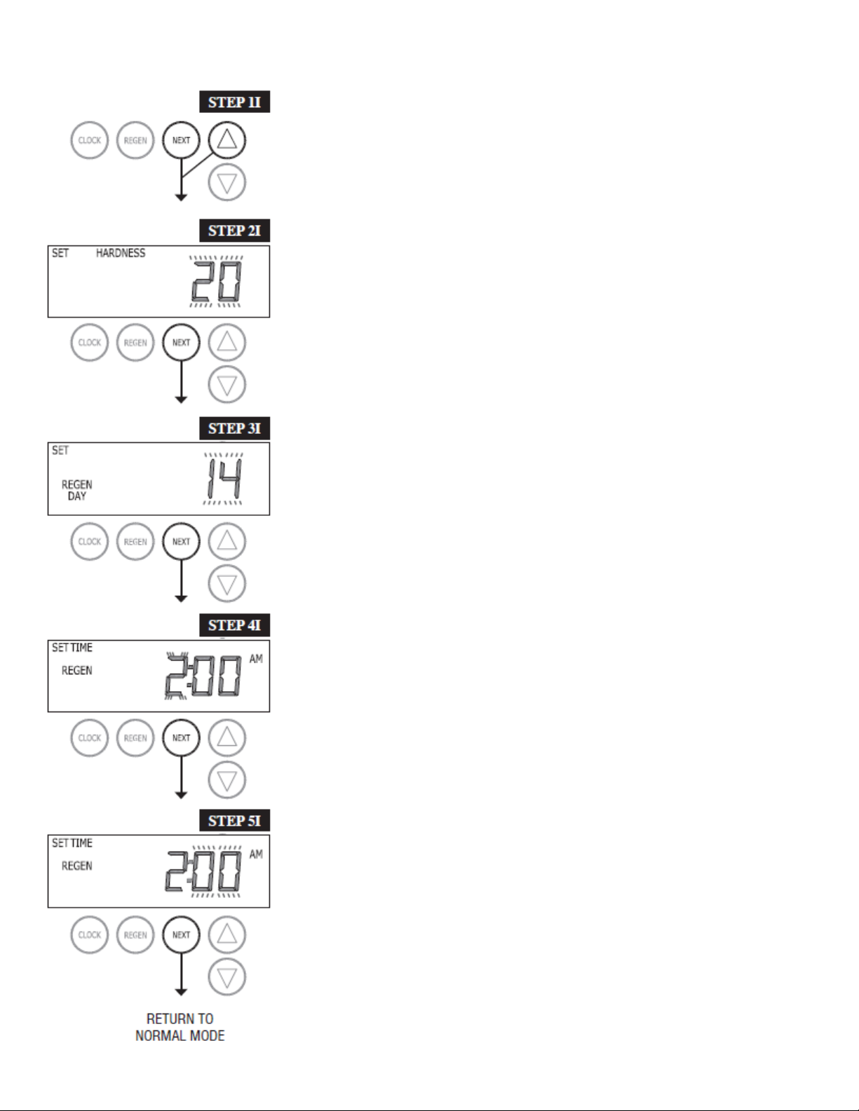
INSTALLER SETTINGS
STEP 1I - Press NEXT and ▲simultaneously for 3 seconds.
STEP 2I –Hardness: Set the amount of hardness in grains of hardness as
calcium carbonate per gallon using the ▲ or ▼ buttons. The default is 20 with
value ranges from 1 to 150 in 1 grain increments. Note: The grains per gallon can
be increased if soluble iron needs to be reduced. This display will show “–nA–”
the system is set up for a filter or if „AUTO‟ is not selected in Step 7S. Press
NEXT to go to step 3I. Press REGEN to exit Installer Display Settings.
STEP 3I –Day Override: When gallon capacity is set to off, sets the number of
days between regenerations. When gallon capacity is set to AUTO or to a
number, sets the maximum number of days between regenerations. If value set
to “oFF” regeneration initiation is based solely on gallons used. If value is set as
a number (allowable range from 1 to 28) a regeneration initiation will be called for
on that day even if sufficient number of gallons were not used to call for a
regeneration. Set Day Override using ▲ or ▼ buttons:
•number of days between regeneration (1 to 28); or
•“oFF”.
See Setting Options Table for more detail on system setup. Press NEXT to go to
step 4I. Press REGEN to return to previous step.
STEP 4I –Next Regeneration Time (hour): Set the hour of day for regeneration
using ▲ or ▼ buttons. AM/PM toggles after 12. The default time is 2:00 a.m. This
display will show “REGEN on 0 GAL” if “on 0” is selected in Step 8S. Press
NEXT to go to step 5I. Press REGEN to return to previous step.
STEP 5I –Next Regeneration Time (minutes): Set the minutes of day for
regeneration using ▲ or ▼ buttons. This display will not be shown if “on 0” is
selected in Step 8S. Press NEXT to exit Installer Display Settings. Press REGEN
to return to previous step.
To initiate a manual regeneration immediately, press and hold the “REGEN”
button for three seconds. The system will begin to regenerate immediately. The
control valve may be stepped through the various regeneration cycles by
pressing the “REGEN” button.

16
NORMAL DISPLAY SETTINGS
GENERAL OPERATION
When the system is operating, one of six displays may be
shown. Pressing NEXT will alternate between the displays.
One of the displays is always the current time of day. The
second display is one of the following: days remaining or
volume remaining. Days remaining is the number of days
left before the system goes through a regeneration cycle.
Capacity remaining is the gallons that will be treated
before the system goes through a regeneration cycle. The
third display shows the current treated water flow rate
through the system. The fourth display shows the total
amount of treated water from 1x1000 to 9999x1000
gallons. This is resettable by simultaneously pressing the
clock and regen buttons for 3 seconds. The fifth display
will show either “dP” or “HoLd” if the dP switch is closed.
The sixth display indicates the user should call for service.
The sixth display will not appear if OFF is selected in Step
12S of OEM System Setup. To clear the Service Call
reminder, press the ▲ and ▼ buttons simultaneously
while CALL is displayed. If a water meter is installed, the
word “Softening” or “Filtering” flashes on the display when
water is being treated (i.e. water is flowing through the
system).
17
REGENERATION MODE
Typically a system is set to regenerate at a time of low water usage. An
example of a time with low water usage is when a household is asleep. If
there is a demand for water when the system is regenerating, untreated
water will be used.
When the system begins to regenerate, the display will change to include information about the step of the
regeneration process and the time remaining for that step to be completed. The system runs through the steps
automatically and will reset itself to provide treated water when the regeneration has been completed.
MANUAL REGENERATION
Sometimes there is a need to regenerate the system
sooner than when the system calls for it, usually referred
to as manual regeneration. There may be a period of
heavy water usage because of guests or a heavy laundry
day.
To initiate a manual regeneration at the preset delayed
regeneration time, when the regeneration time option is
set to “NORMAL” or “NORMAL + on 0”, press and release “REGEN”.
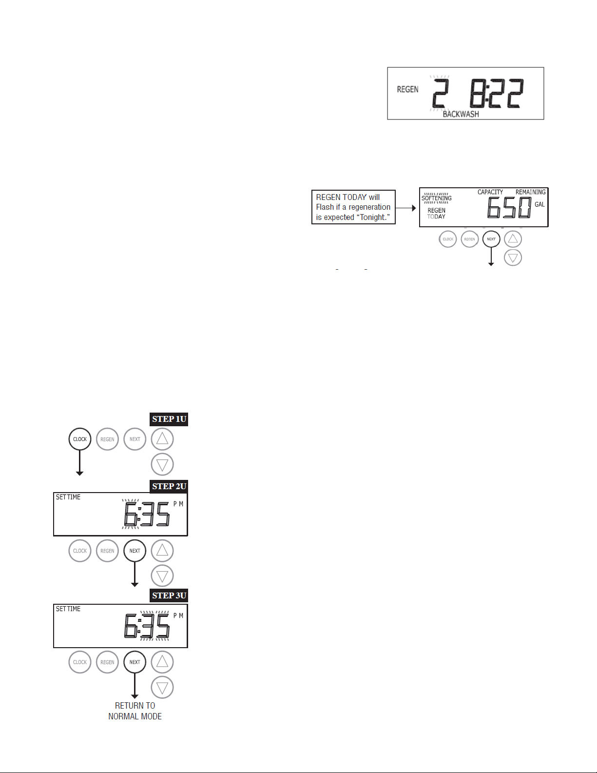
The words “REGEN TODAY” will flash on the display to indicate that the system will regenerate at the preset
delayed regeneration time. If you pressed the “REGEN” button in error, pressing the button again will cancel the
request. Note: If the regeneration time option is set to “on 0” there is no set delayed regeneration time so “REGEN
TODAY” will not activate if “REGEN” button is pressed.
To initiate a manual regeneration immediately, press and hold the “REGEN” button for three seconds. The system
will begin to regenerate immediately. The request cannot be cancelled.
Note: For softeners, if brine tank does not contain salt, fill with salt and wait at least two hours before regenerating.
SET TIME OF DAY
The user can also set the time of day. Time of day should only need to be set
after extended power outages or when daylight saving time begins or ends. If
an extended power outage occurs, the time of day will flash on and off which
indicates the time of day should be reset.
STEP 1U –Press CLOCK.
STEP 2U
STEP 2U - Current Time (hour): Set the hour of the day using ▲ and ▼
buttons. AM/PM toggles after 12. Press NEXT to go to step 3U.
STEP 3U - Current Time (minutes): Set the minutes of the day using ▲ and ▼
buttons. Press NEXT to exit Set Time of Day. Press REGEN to return to
previous step.
STEP 3U
STEP 1D
STEP 2D
STEP 3D
STEP 4D
STEP 5D
18
GENERAL INFORMATION
POWER LOSS
If the power goes out for less than two hours, the system will automatically reset itself. If an extended power outage
occurs, the time of day will flash on and off which indicates the time of day should be reset. The system will
remember the rest.
ERROR MESSAGE
If the word “ERROR” and a number are alternately flashing on the display this indicates that the valve was not able
to function properly.
GENERAL BUTTON OPERATION

19
START UP INSTRUCTIONS
• After installation is completed rotate the bypass handles to the bypass position
(see bypass valve diagram page ).
• Turn on water and check for leaks.
• Fully open a cold water faucet.
• Allow water to run until clear to rid pipes of debris which may have occurred during installation.
• The system is now ready for filling with water and for testing.
1. With the bypass valve in the bypass position, manually pour enough water into the brine tank to reach the
top of the air check valve.
2. Press and hold the REGEN button until the motor starts. Release button. Wait until the display reads
“BACKWASH” and the remaining time is counting down. Unplug transformer to prevent valve from moving
to the next cycle.
3. Open the inlet handle of the bypass valve very slightly allowing water to fill the tank slowly in order to expel
air.
CAUTION: If water flows too rapidly there will be a loss of media.
4. When the water is flowing steadily to the drain without the presence of air, restore power and momentarily
press the REGEN button to advance the control to the “BRINE” position.
5. Fully open the inlet bypass valve handle (bypass is now in the diagnostic position).
Check to verify that water is being drawn from brine tank.
There should be a slow flow to the drain.
Allow two minutes for the media bed to settle.
6. Momentarily press REGEN again until the display reads “2 BACKWASH” and the “time remaining” numbers
are counting down. The “2” flashes.
7. Momentarily press REGEN again until the display reads “RINSE”. Unplug transformer. There should be a
rapid flow to the drain. Allow to run until steady, clear, and without air.
Restore power.
8. Set bypass valve handles to the normal operating position
9. Momentarily press REGEN again until the display reads “FILL”.
Allow the brine tank to fill automatically.
It will fill with the proper volume of water for the first regeneration after the unit will automatically return to
the service position. If not filling automatically, press REGEN to advance the valve to service.
10. While the brine tank is filling, load it with water softener salt.
Table of contents
Other Water Depot Water Dispenser manuals


