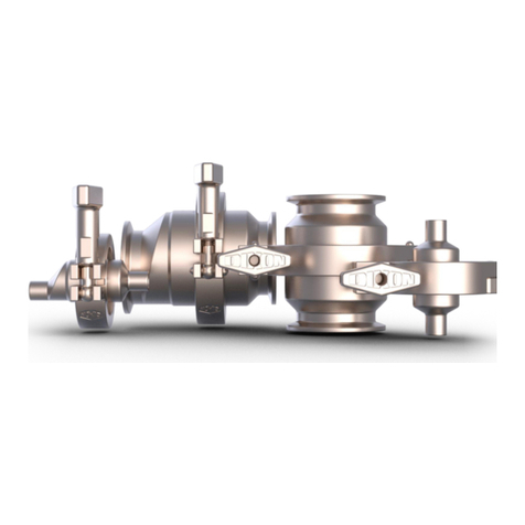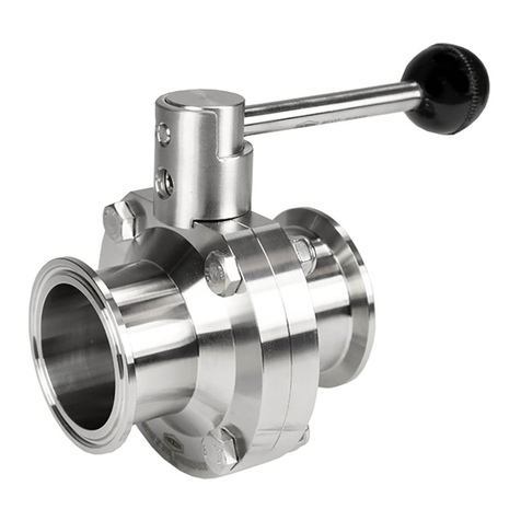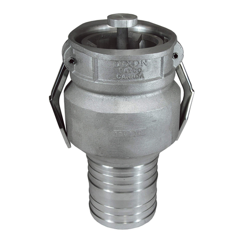
Air & Vacuum Relief Tank Vent Valve
Installation & Operation
This valve has been designed as a secondary safety pressure and vacuum relief vent. Always open the upper manhole
whenever a product is being transferred in excess of 250 GPM.
Receiving & Unpacking Instructions
1. Carefully unpack and inspect for any damage in shipping.
2. Inspect the exterior to ensure the screen is not dented.
3. Push up on the pressure plate under the valve and inspect to ensure the O-rings are not dislodged.
All tolerances have been designed to be extremely close to holding a positive head pressure. Be careful when cleaning and
assembling not to damage components or O-ring sealing surfaces. If any of these items become damaged, the vent may
not work properly.
Cleaning Instructions
1. Valvemustbecleanedwheneveroverllingofthetankhasoccurred.
2. Completely disassemble the valve and wash all parts separately. Be careful not to damage any components.
3. Remove all O-rings. Clean inside O-ring grooves. Inspect all O-rings and replace them if needed.
4. Clean the inside of the sleeve where the vacuum bolt (3) slides. The vacuum bolt must slide freely to operate properly.
5. All O-ring sealing surfaces must be clean and DRY.
Assembly Procedure
1.
Install vacuum O-ring (6) onto pressure plate (8), (inspect O-ring and be certain O-ring is not twisted, this can cause
vacuum disk not to seal properly). Be careful not to roll or stretch the O-ring when pressing into the groove. Press
straightdownonly.InspecttheO-ringtoensureitislyingat.
2. Install pressure O-ring (7) onto pressure plate (8). Inspect O-ring and be certain the O-ring is not twisted; this can cause
the vacuum disk not to seal properly. Be careful not to roll or stretch O-ring when pressing into the groove. Press
straightdownonly.InspecttheO-ringtoensureitislyingat.
3. Slide small O-ring (4) onto vacuum bolt (3); insert vacuum bolt through the vacuum disk (5) with the head of the bolt
oppositetheatsideofthevacuumdisc.PressthesmallO-ring(4)upintothecounterboreinthevacuumdisk(5).
4. Insert vacuum bolt (3) through the center of the pressure plate (8).
5. Slide vacuum spring (9) over vacuum bolt (3) and pressure plate (8). While holding down vacuum spring (9), assemble
atwasher(10)andlocknut(11).ONLYTIGHTENNUTFARENOUGHTOSEEBOLTEVENWITHTHETOPOFTHENUT.
6. Setmainbody(1)onaatsurfacewithclampconnectiondown.
7. Positionthelargepressureplate(8),withvacuumdiscdown,overthemainbody(1).Lineupholesinthepressureplate
(8) with screw holes in the body.
8. Insert the three cover screws (16) through the holes in the cover (15). Turn the cover sideways. While holding the
screws (16) from falling out with the palm of your hand, slide the three spacers (14) and the three pressure plate
springs (13) onto the three screws (16).
9. Holdingthesprings(13)fromfallingoff,guidethethreescrewsthroughthepressureplate(8).
10. Thread the three screws (16), one turn only, into the main body (1).
11. Spread the screen (12) open just enough to slide it over the cover (15) and around the three springs (13).
12. Start one side of the air screen (12) into the small groove located in the top of the body (1). While holding the cover (15)
down with one hand, work the screen (12) around the body (1) until the entire screen (12) is seated into the groove.
13. While continuing to hold down the cover (15), use a 4mm Allen Wrench to tighten the three cover screws (16). Do not
over-tighten the screws (16).
Product:TVSEC-Series

